

Page 1

R
INSTALLATION AND OPERATING INSTRUCTIONS
Electric Griddles, Drop-In Style
Models: EGD-48 & EGD-72
IMPORTANT FOR FUTURE REFERENCE
Please complete this information and retain this manual for the life of the equipment. For
WarrantyServiceand/or Parts,this information isrequired.
ModelNumber SerialNumber DatePurchased
CONTENTS
General Information
Safety Precautions
Specifications & Dimensions
General Installation Instructions
Electrical Data
Owners Information
Care & Cleaning
Servicing
Wiring Diagrams
Replacement Parts List
Warranty
WARNING:
vicinity of this or any other appliance. Keep the area free and clear of combustibles. (See ANZI
!
Z83.14B,1991)
WARNING:
damage, injury or death. Read and understand these instructions thoroughly before
!
positioning,installing, maintaining orservicing thisequipment.
For your safety do not store or use gasoline or other flammable vapors or liquids in the
Improper installation, operation, service or maintenance can cause property
2
3
3
4
6
6
7
7
8
10
11
!
!
P/N 88060-50 9/05
APW WYOTT Foodservice Equipment Company
P.O. Box 1829
Cheyenne, WY 82003
+1(307) 634-5801 Phone +1(800) 752-0863 TollFree
+1(307) 637-8071 Fax www.apwwyott.com
1
Page 2
GENERAL INFORMATION
THIS MANUAL SHOULD BE RETAINED FOR FUTURE REFERENCE
CAUTION:
positioned so the general public can use the equipment, make sure that cautions, warnings, and
operating instructions are clearly posted near each unit so that anyone using the equipment will
!
useit correctly andnotinjure themselves or harmtheequipment.
WARNING:
injury or death. Read and understand these instructions thoroughly before positioning, installing,
!
maintainingorservicingthis equipment.
WARNING:
strongly recommendhaving a competentprofessional install the equipment.A licensed electrician
should make the electrical connections and connect power to the unit. Local codes should always
!
be used when connecting these units to electrical power. In the absence of local codes, use the
latestversionof theNationalElectricalCode.
WARNING:
vicinity of this or any other appliance. Keep the area free and clear of combustibles. (See ANZI
!
Z83.14B,1991)
NOTICE:
Thesemay be obtainedfromthegas supplier.
!
WARNING:
manualfor future reference Ovenmustbe kept clear ofcombustiblesat all times
!
These models are designed, built, and sold for commercial use. If these models are
Improper installation, operation, service or maintenance can cause property damage,
Installper the spacing requirements listedin the installation section of this manual. We
For your safety do not store or use gasoline or other flammable vapors or liquids in the
Instructions to be followed if anyone smells gas should be posted in a prominent place.
This product is intended for commercial use only. Not for household use Retain this
!
!
!
!
!
!
WARNING: -
!
IMMEDIATELY INSPECT FORSHIPPING DAMAGE
All containers should be examined for damage before and during unloading. The freight carrier has
assumed responsibility for its safe transit and delivery. If equipment is received damaged, either apparent
or concealed, aclaim mustbe madewith the deliveringcarrier.
A) Apparent damage or loss must be noted on the freight bill at the time of delivery. It must then be signed
by the carrier representative (Driver). If this is not done, the carrier may refuse the claim. The carrier can
supplythe necessaryforms.
B) Concealed damage or loss if not apparent until after equipment is uncrated, a request for inspection
must be made to the carrier within 15 days. The carrier should arrange an inspection. Be certain to hold all
contentsand packagingmaterial.
Installationand start-up should be performedby a qualifiedinstaller whothoroughly read, understands and
followsthese instructions.
If you have questions concerning the installation, operation, maintenance or service of this product, write
Technical Service DepartmentAPW/Wyott Foodservice Equipment Company, P.O. Box 1829, Cheyenne,
WY82003.
Congratulations on your purchase of APW Wyott commercial cooking or refrigeration equipment.
Wyott
and maintenance, you will experience years of reliable operation from this equipment. To ensure best
results,it isimportant that youread andfollow theinstructions in this manual carefully.
takes pride in the design and quality of our products. When used as intended and with proper care
SHOCKHAZARD
Donot open anypanelsthatrequire the useoftools.
!
APW
LOCATION OF DATAPLATE
Thedata plateis locatedon the front panel.
2
Page 3
SAFETY PRECAUTIONS
Before installing and operating this equipmentbe sureeveryone involvedin its operation is fullytrained and
is aware of all precautions. Accidents and problems can result by a failure to follow fundamental rules and
precautions.
The following words and symbols, found in this manual, alert you to hazards to the operator, service
personnelor theequipment.The wordsare definedas follows.
DANGER:
death.
!
WARNING:
in serious injuryor death.
!
CAUTION:
minoror moderateinjury orproduct orproperty damage.
!
NOTICE:
understoodeven thoughnot dangerous.
!
This symbol warns of imminent hazard which will result in serious injury or
This symbolrefers to a potential hazardor unsafe practice,which couldresult
This symbol refersto a potential hazardor unsafepractice, whichmay resultin
This symbol refers to information that needs special attention or must be fully
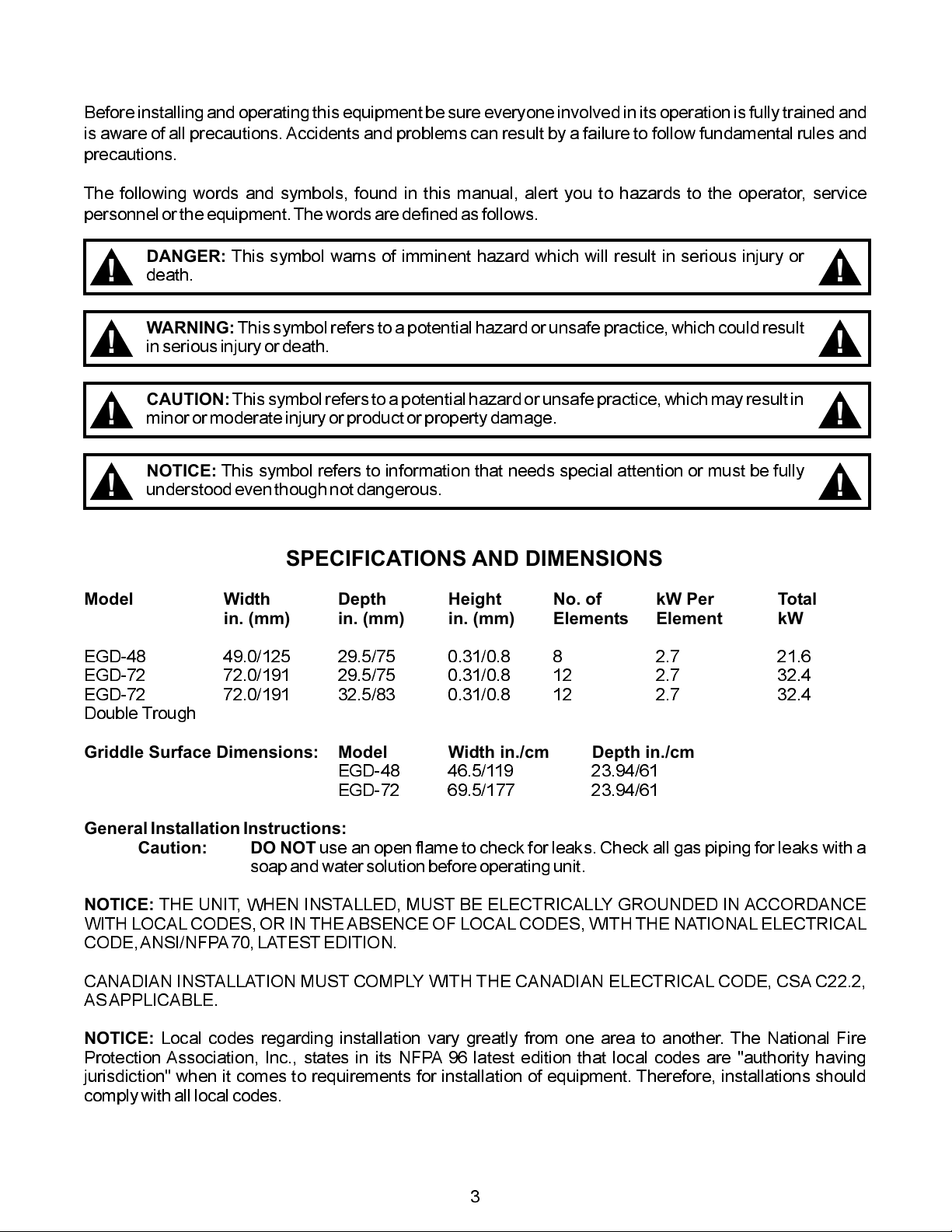
SPECIFICATIONS AND DIMENSIONS
Model Width Depth Height No. of kW Per Total
in. (mm) in. (mm) in. (mm) Elements Element kW
EGD-48 49.0/125 29.5/75 0.31/0.8 8 2.7 21.6
EGD-72 72.0/191 29.5/75 0.31/0.8 12 2.7 32.4
EGD-72 72.0/191 32.5/83 0.31/0.8 12 2.7 32.4
Double Trough
!
!
!
!
Griddle Surface Dimensions: Model Width in./cm Depth in./cm
EGD-48 46.5/119 23.94/61
EGD-72 69.5/177 23.94/61
General Installation Instructions:
Caution: DO NOT
soapand watersolution beforeoperating unit.
NOTICE:
WITH LOCAL CODES, OR IN THE ABSENCE OF LOCALCODES, WITH THE NATIONAL ELECTRICAL
CODE,ANSI/NFPA70,LATESTEDITION.
CANADIAN INSTALLATION MUST COMPLY WITH THE CANADIAN ELECTRICAL CODE, CSA C22.2,
ASAPPLICABLE.
NOTICE:
Protection Association, Inc., states in its NFPA 96 latest edition that local codes are "authority having
jurisdiction" when it comes to requirements for installation of equipment. Therefore, installations should
complywith alllocal codes.
THE UNIT, WHEN INSTALLED, MUST BE ELECTRICALLY GROUNDED IN ACCORDANCE
Local codes regarding installation vary greatly from one area to another. The National Fire
use an open flame to check for leaks. Check all gas piping for leaks with a
3
Page 4
GENERAL INSTALLATION INSTRUCTIONS
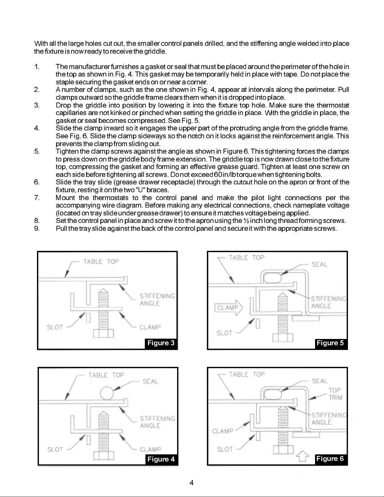
With all the large holes cut out, the smaller control panels drilled, and the stiffening angle welded into place
thefixture isnow readyto receivethe griddle.
1. The manufacturerfurnishes agasket or seal that must be placed aroundthe perimeter of the holein
the top as shown in Fig. 4.This gasket may be temporarily held in place with tape.Do not place the
staplesecuring thegasket ends onor neara corner.
2. A number of clamps, such as the one shown in Fig. 4, appear at intervals along the perimeter. Pull
clampsoutward sothe griddle frameclears themwhen itis droppedinto place.
3. Drop the griddle into position by lowering it into the fixture top hole. Make sure the thermostat
capillaries are not kinkedor pinched when setting the griddle in place. With the griddle in place, the
gasketor sealbecomes compressed.See Fig. 5.
4. Slide the clamp inward so it engages the upper part of the protruding angle from the griddle frame.
See Fig. 6. Slide the clamp sideways so the notch on it locks against the reinforcement angle. This
preventsthe clampfrom sliding out.
5. Tightenthe clamp screws against the angle as shown in Figure 6.This tightening forces the clamps
to pressdown on the griddle body frame extension. The griddletop is nowdrawn close tothe fixture
top, compressing the gasket and forming an effective grease guard. Tighten at least one screw on
eachside beforetightening allscrews. Do not exceed 60in/lb torquewhen tighteningbolts.
6. Slide the tray slide (grease drawer receptacle) through the cutout hole on the apron or front of the
fixture,resting iton thetwo "U"braces.
7. Mount the thermostats to the control panel and make the pilot light connections per the
accompanying wire diagram. Before making any electrical connections, check nameplate voltage
(locatedon trayslide undergrease drawer)to ensure itmatches voltagebeing applied.
8. Setthe controlpanel inplace and screwit tothe apronusing the½ inchlong threadformingscrews.
9. Pullthe trayslide againstthe backof thecontrol panel andsecure itwith theappropriatescrews.
Figure 3
Figure 4
Figure 5
Figure 6
4
Page 5

Electrical Connections
Terminal Box Location:
The terminal boxes can be located at either the left front or right rear of the griddle. When shipped
from the factory the device has the terminal box attached in the left front position. The box can be
relocatedto thealternate positionby removing twoscrews.
Loading:
Electricalloadings ofthe griddlescovered by thisinstruction aretabulated below.
Fusing:
Griddleis notfused andmust beconnected to a properly fusedcircuit.
Grounding:
Griddle mustbe grounded inaccordance with theNational Electrical Codeand applicable local
codes.
U.L. CONDITIONS OF ACCEPTABILITY:
1. This equipment must be installed in an all metal fixture of steel or stainless steel construction,
.078 inchthick minimumfor the topand supportingframe. Side enclosure to beat least 22MSG
minimumthickness.
2. Aremovable bottom enclosure must be providedunder each drop-in unitand be made of metal
construction of at least 22 MSG minimum. If ventilating openings are provided in the bottom
enclosure, they must not allow the entrance of ¾ inch diameter rod nor be located directly
belowuninsulated liveterminals.
3. Minimum spacing betweengriddle top edgeand adjacentitems should be: fixture backwall 1 ¾
inch,fixture sideenclosure 1inch, frontcontrol panel 7/8inch, otherdrop-in devices 1inch.
4. Controlsshall be mountedon thefront verticalsurface of the fixture.
5. Forsupply connections, usewire suitablefor at least90° C(194° F).
NOTES: .
1. Griddle can be mounted with the trough in the front or rear, dimensions shown are for front
troughmounting. Forrear troughmounting,this dimensionmust bebetween 7/8and 2 inches.
2. Tabletopreinforcement andgasket furnished withthe griddle.
3. At the factory, the electrical connection box was installed in the front position. The connection
boxcan bemoved tothe rearlocation shown.
IMPORTANT:
1. Any dimension smaller than the minimum or larger than the maximum shown in the table will
require corresponding changes to the grease chute by the fabricator by adding an extension to
preventthe greasefrom spillinginto the cabinet.
2. Any dimensions smaller than minimum given will require additional panels or sides and back to
facilitateservicing.
3. The minimum dimension from the back of the control panelto the front of the griddle top is 7/8 inch
regardlessof theshape ofthe bullnoseor table overhang.
4. Griddles are shipped from the factory with dimension "D" at 7 7/16 inch. Moveable braces permit
5
Page 6

thefabricator toeasily varythis dimensionup to 1 0 7/16inches inincrements of ¾ inch.
5. The minimum space between adjacent griddles must be 1 5/8 inch and between any other
combinationof dropin cookingequipment must be1 inch.
6. Electricalwiring crossingthe trayslide is to be placedunder thetray slideand notabove it.
7. The installer or servicer must put the electrical wiring near the control panel inside the wire guide
beforeattaching thecontrol panel tothe fixturefront.
IMPORTANT STEPS ININSTALLATION:
1. Griddle positionto be nocloser than7/8 inchfrom componentframe edge andcontrol panel.
2. Install the gasket between the griddle top and the table top before clamping. Exercise caution so
thatthe griddletop doesnot pinchor damagethe gasket.
ELECTRICAL DATA
-
-
- -
- - -
OWNER'S INFORMATION
Cleaning the GriddleAfter Uncrating:
Before using for the first time, be sure to remove the factory-applied rust preventative compound.
Add a mild detergent to hot water and wash the griddle well. Rinse with a clean, damp cloth and
wipedry.
The Controls:
Turning the dial knob (recessed in the front control panel) controls the heat of the griddle surface.
Whenat leastone controlis turnedon, asignal lightin theupper left-handcornerof thecontrol panel
will glow continuously. Thus,the operatorknows at a glance whetheror not the griddle isenergized.
Separate signal light cycles with each control. Whenever the thermostat calls for heat, the signal
light associated with it will be on. Each thermostat controls twelve inches of griddle surface width.
Thermostattemperature range is200°- 450°F+/- 10°F.
Seasoning the Griddle Surface:
After thorough cleaning, the griddle is ready for seasoning. Preheat to 400°F. When the dialed
temperature is reached asindicated by thesignal lightsgoing off,spread a lightfilm of cookingoil or
fat overthe entire surface of thegriddle. In two minutes, wipethe griddle clean of excessoil. Repeat
thisoperation. Thegriddle is now ready foruse.
Operating Instructions:
1. Preheat griddle (preheat time, 77°F - 350°F, approximately 8 minutes). Set the thermostat dials at
the correct griddlingtemperature for the food to be cooked. A red light will flash on automatically for
each section of the griddle when the dial is set and will flash off when the section has reached the
dialed temperature. (The signal light will flash on and off during the cooking operation to show that
correcttemperature isbeing maintained.)Youare nowready to loadthe griddle.
6
Page 7

2. Load Griddle. After preheating, load griddle and cook according to recipe. Turn foods halfway
throughcooking timeunless otherwisespecifiedin recipe.
Economy Hint:
-oz. slices, 3/8 thick)
Fried
Turn griddleOFF(or tolowest thermostatsetting)during idleperiods.
-48 -72MODEL EGD MODEL EGD
CAPACITIES QTY
PER
LOAD
MEATS
-
-oz. steaks, )
-oz. steaks, 1" thick)
-
OTHER
FOODS
APPROX
HOURLY
PRODUCTION LOAD
30 Ibs.
70 Ibs
QTY
PER
APPROX COOKING
HOURLY
PRODUCTION
40 Ibs
93 Ibs
1000+
1470+
BOTH MODELS
TIME
& TEMP
CARE & CLEANING
1. IMPORTANT:Atthe end of each daysoperation, turn all temperature controlsto OFF.
2. After each cooking load, scrape the griddle surface with scraper or rigid spatula to remove excess
fat and food particles. ONCE A DAY, or whenever necessary, thoroughly clean and wipe out the
grease trough.As necessary during use, wipe out accumulated material to provide good drainage.
Removegrease drawer, emptyand wash. In general, soapand waterwith theaid ofa spongeor soft
cloth will clean the drawer thoroughly. Wipe clean with a damp cloth and dry. Clean control panel
witha dampcloth anddry.
3. EACH WEEK, or whenever necessary, clean griddle thoroughly. If desired, use a pumice or griddle
stone over surface. Rub with the grain of the metal while still warm. Avoid steel wool! After each
thorough cleaning, the cookingsurface must bereseasoned. Toremove controlknobs for cleaning,
pullstraight out.Washin soapywater.Rinse, dry and replace onshaft.
SERVICING
Your griddle is covered by a one-year written warranty on parts and labor. If this device should require
service, call your local commercial equipment dealer or authorized service station. The nameplate
indicating the pertinent electrical data of the griddle is located in the front of the grease drawer receptacle
andcan beseen readilywhen thedrawer is removed.
7
Page 8

EGD-48 WIRING DIAGRAM
L1
L2
L3
Page 9

EGD-72 WIRING DIAGRAM
Griddle
(Bottom View)
Thermostat
Bulb
ALTERNATE WIRING
FOR TWO
POWER SUPPLIES
Page 10

PARTS LIST DROP-IN ELECTRIC GRIDDLES, EGD-48 & EGD-72
ITEM
PART NUMBER
14397-25
14397-26
642567 -01
646378-03
646251-01
642578-01
642579-01
11260-35
647392-01
647395-01
642584-02
642584-01
643066-01
643356-03
DESCRIPTION
BOTTOM PANEL, EGD -48, R.H.
BOTTOM PANEL, EGD -48, L.H.
BOTTOM PANEL, EGD -72, SINGLE TROUGH
BOTTOM PANEL, EGD -72, DOUBLE TROUGH
BRACE ASSEMBLY, EGD -48
BRACE ASSEMBLY, EGD -72
653844-01
642625-09
15139-03
31100-82
644635-05
82111-00
84315-00
31101-30
84171-00
81413-00
84364-00
85195-00
84317 -00
84362-00
85196-00
CONTROL PANEL ASSEMBLY
KNOB ASSEMBLY
INDICATOR LIGHT
CONTROL PANEL SEAL
THERMOSTAT ASSEMBLY
SCREW, 1/4-20 X 3/4
HEX NUT, 1/4 -20
SCREW, 10-32 X 1/2
HEX NUT, 10 -32
SCREW, SELF-TAPPING, 8 -32 X 1/2
WING NUT, 5/16 -18
FLAT WASHER, 5/16
HEX NUT, 1/4 -20
HEX NUT, 5/16 -18
FLAT WASHER, 1/4
642626-06
642626-07
642626-10
GASKET, GRIDDLE TOP, EGD -48
GASKET, GRIDDLE TOP, EGD -72, SINGLE TROUGH
-
GASKET, GRIDDLE TOP, EGD
10
72, DOUBLE
TROUGH
Page 11

APW WYOTT EQUIPMENT LIMITED WARRANTY
APW Wyott Foodservice Equipment Company warrants it'sequipment against defects in materials and workmanship, subject to the
following conditions:
This warranty applies to the original owneronlyandisnotassignable.
Should any product fail tofunction in its intended manner under normal use within the limits defined in this warranty,at the option of
APW Wyott such product will be repaired or replaced by APW Wyott or its Authorized Service Agency. APW Wyott will only be
responsible for charges incurred or service performed by its Authorized Service Agencies. The use of other than APW Wyott
Authorized Service Agencies will void this warranty andAPWWyottwill not beresponsible for such work orany charges associated
with same. The closestAPWWyottAuthorized ServiceAgent must be used.
This warranty covers products shipped into the 48 contiguous United States,Hawaii, metropolitan areas of Alaska and Canada. There
will be no labor coverage for equipment locatedonanyislandnotconnected by roadway to the mainland.
Warranty coverage on products used outside the 48 contiguous United States, Hawaii, and metropolitan areas of Alaska and Canada
may vary.ContacttheinternationalAPWWyott distributor, dealer, or service agency for details.
TimePeriod
One year for parts and one year for labor,effective from the date of purchase by the original owner. The Authorized Service Agency
may, at their option, require proof of purchase. Parts replaced under this warranty are warranted for the un-expired portion of the
original product warranty only.
Exceptions
Inallcases, parts covered by extended warranty willbeshipped FOB the factory after the first year.
Portable Carry In Products
Equipment weighing over 70 pounds or permanently installed will be serviced on-site as per the terms of this warranty. Equipment
weighing 70 pounds or under, and which is not permanently installed, i.e. with cord and plug, is considered portable and is subject to
the following warranty handling limitations. If portable equipment fails to operate in its intended manner on the first day of
connection, or use, atAPWWyott'soptionoritsAuthorized ServiceAgency, it will be serviced on site or replaced.
From day two through the conclusion of this warranty period, portable units must be taken to or sent prepaid to the APW Wyott
Authorized Service Agency for in-warranty repairs. Nomileageortravelcharges are allowed on portable units after the firstdayofuse.
If the customer wants on-site service, they may receive same by paying the travel and mileage charges. Exceptions to this rule: (1)
countertop warmers andcookers, which are covered underthe Enhanced Warranty Program, and (2) toastersor rollergrills which have
instore service.
Exclusions
The following conditions are not covered bywarranty:
If the equipment has been changed, altered, modified or repaired by other than an Authorized Service Agency during or after the
warranty period, thenthe manufacturer shallnot be liable forany damages to anyperson or to any property,whichmay result from the
use of the equipment thereafter.
This warranty does not cover services performed at overtime or premium labor rates. Should service be required at times which
normally involve overtime orpremiumlabor rates, the owner shall be charged forthedifferencebetween normal service rates and such
premium rates.APWWyott does not assume anyliabilityforextended delays in replacing or repairing anyitemsbeyonditscontrol.
Inallcases, the use of other thanAPWWyottAuthorized OEM ReplacementParts will void this warranty.
This equipment is intended for commercial useonly.Warranty is void if equipment is installed in other thancommercial application.
WaterQualityRequirements
Water supply intended for a unit that has in excess of 3.0 grains of hardness per gallon (GPG) must be treated or softened before
being used. Water containing over 3.0 GPG will decrease the efficiency and reduce the operation life of the unit.
Note: Product failure caused by liming or sediment buildup is not covered under warranty.
THE FOREGOING WARRANTY IS IN LIEU OFANYAND ALL OTHER WARRANTIES EXPRESSED OR IMPLIED
INCLUDING ANY IMPLIED WARRANTY OF MERCHANTABILITY OR FITNESS FOR PARTICULAR PURPOSES
AND CONSTITUTES THE ENTIRE LIABILITY OFAPW WYOTT. IN NO EVENT DOES THE LIMITED WARRANTY
EXTEND BEYOND THE TERMS STATEDHEREIN.
*Gas/Electric Cookline:
component parts, except switches andthermostats. (2 additional years on parts only. No labor on second or third year.)
*BroilerBriquettes,
*Heat Strips:
*GlassWindows, Doors, Seals, Rubber Seals, Light Bulbs:
*Equipment failure relating to improper installation, improper utility connection or supply and problems due to
ventilation.
*Equipment that has not been properly maintained, calibration of controls, adjustments, damage from improper cleaning
and water damage to controls.
*Equipment that has not been used in an appropriate manner, or has been subject to misuse or misapplication, neglect,
abuse, accident, alteration, negligence, damageduring transit, delivery or installation, fire,flood,riotoractofgod.
*Equipment that has the model number orserialnumberremoved or altered.
Models FD, FDL, FDD, FDDL. Two (2)Year Warrantyonelementonly. No labor second year.
Models GCB, GCRB, GF, GGM, GGT, CHP-H, EF, EG, EHP. Three (3) Year Warranty on all
RockGrates,CookingGrates,BurnerShields,Fireboxes:
90Day Material Only. No Labor.
90DayMaterialOnly.NoLabor.
9/05
11
Page 12

R
24 Hour Toll Free
Service Hot Line:
1-800-733-2203
APW WYOTT Foodservice Equipment Company
P.O. Box 1829
Cheyenne, WY 82003
+1(307) 634-5801 Phone (800)752-0863 TollFree
+1 (307) 637-8071 Fax www.apwwyott.com
12
+1
 Loading...