

Page 1

R
INSTALLATION AND OPERATING INSTRUCTIONS
Electric Griddles, Drop-In Style
Models: EGD-1824, 1836, 1848, 2436, 2448, 2472
Please complete this information and retain this manual for the life of the equipment. For
WarrantyServiceand/or Parts,this information isrequired.
ModelNumber SerialNumber DatePurchased
CONTENTS
Installation Cutouts
Electrical Connections
General
U.L. Conditions Of Acceptability
Layout
Installation
Owners Information
Cleaning The Griddle After Uncrating
Controls
Seasoning The Griddle Surface
Operating Instructions
Care & Cleaning
Parts Lists & Exploded Views
Warranty
WARNING:
liquids in the vicinity of this or any other appliance. Keep the area free and clear of
!
combustibles.(SeeANZI Z83.14B,1991)
WARNING:
damage, injury or death. Read and understand these instructions thoroughly before
!
positioning,installing, maintaining orservicing thisequipment.
For your safety do not store or use gasoline or other flammable vapors or
Improper installation, operation, service or maintenance can cause property
2
7
13
13
13
13
15
15
15
15
15
15
16
20
!
!
P/N 88057-10 9/05
APW WYOTT Foodservice Equipment Company
P.O. Box 1829
Cheyenne, WY 82003
+1(307) 634-5801 Phone +1(800) 752-0863 TollFree
+1(307) 637-8071 Fax www.apwwyott.com
1
Page 2
U.L. CONDITIONS OF ACCEPTABILITY
A. This equipment must be installed in an all metal fixture of steel or stainless steel construction, .078
inchthick minimumfor thetop andsupporting frame.Side enclosure to be at least 22 MSG minimum
thickness.
B. A removable bottom enclosure must be provided under each drop-in unit and be made of metal
construction of at least 22 MSG min. If ventilating openings are provided in the bottom enclosure
they must not allowthe entranceof a3/4 inchdiameter rodnor be located directly below uninsulated
liveterminals.
C. Minimum spacing between griddle top edge and adjacent items should be: Fixture back wall 1-3/4
inch,Fixture sideenclosure 1inch, Frontcontrolpanel 7/8inch, Otherdrop-in devices 1inch.
D. Controlsshallbe mountedon thefront vertical surfaceof thefixture.
E. Forsupply connectionsuse wiresuitablefor atleast 90degrees Celsius(194 degrees Fahrenheit).
NOTES:
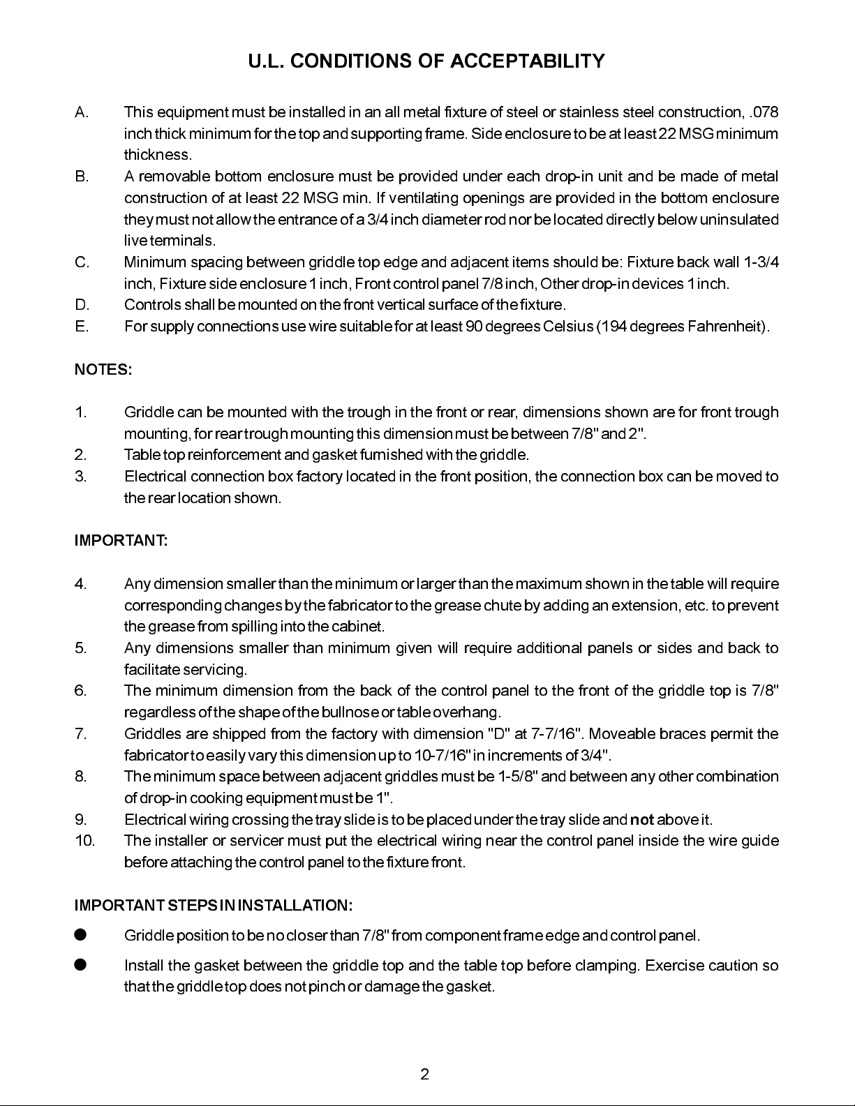
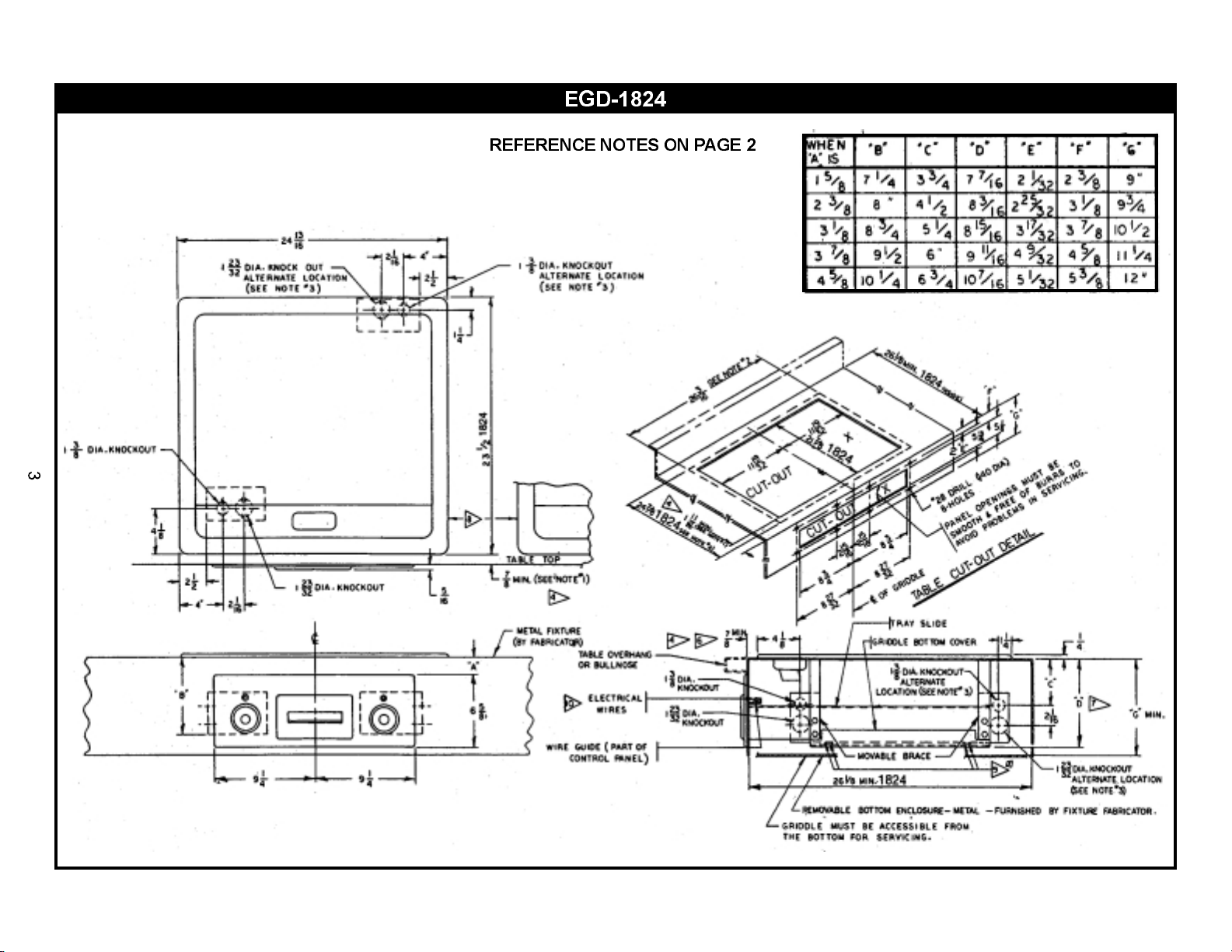
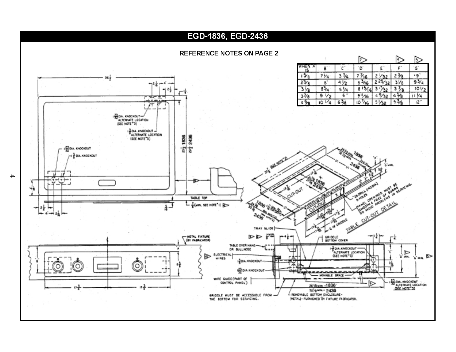
1. Griddle can be mounted with the trough in the front or rear, dimensions shown are for front trough
mounting,for reartrough mountingthis dimension mustbe between7/8" and2".
2. Tabletop reinforcementand gasket furnishedwith thegriddle.
3. Electrical connection box factory located in the front position, the connection box can be moved to
therear locationshown.
IMPORTANT:
4. Any dimension smaller thanthe minimumor larger than the maximumshown inthe table will require
correspondingchanges bythe fabricatorto the greasechute byadding anextension, etc.to prevent
thegrease fromspilling intothe cabinet.
5. Any dimensions smaller than minimum given will require additional panels or sides and back to
facilitateservicing.
6. The minimum dimension from the back of the control panel to the front of the griddle top is 7/8"
regardlessof theshape ofthe bullnoseor table overhang.
7. Griddles are shipped from the factory with dimension "D" at 7-7/16". Moveable braces permit the
fabricatorto easilyvary thisdimension up to 10-7/16" inincrementsof 3/4".
8. The minimumspace betweenadjacent griddles mustbe 1-5/8" andbetween any othercombination
of drop-in cookingequipment mustbe 1".
9. Electricalwiring crossingthe trayslide is to be placedunder thetray slideand aboveit.
10. The installer or servicer must put the electrical wiring near the control panel inside the wire guide
beforeattaching thecontrol panel tothe fixturefront.
IMPORTANT STEPS ININSTALLATION:
!
Griddleposition tobe nocloser than7/8" from componentframe edgeand controlpanel.
not
!
Install the gasket between the griddle top and the table top before clamping. Exercise caution so
thatthe griddletop doesnot pinchor damagethe gasket.
2
Page 3
EGD-1824
REFERENCE NOTES ON PAGE 2
Page 4
EGD-1836, EGD-2436
REFERENCE NOTES ON PAGE 2
Page 5
EGD-1848, EGD-2448
REFERENCE NOTES ON PAGE 2
Page 6
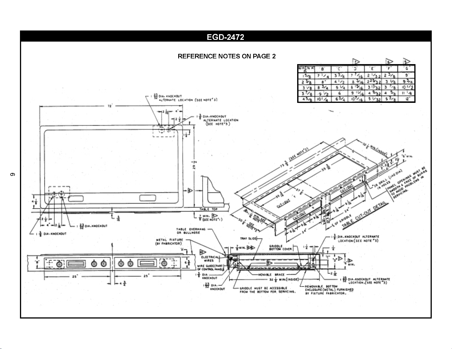
EGD-2472
REFERENCE NOTES ON PAGE 2
Page 7

ELECTRICAL CONNECTIONS
WARNING:
electricalcode and/orother localelectrical codes.
WARNING:
areworking onthe circuit.
Terminal Box Location.
the right rear of the griddle. When shipped from the factory, the device has the terminal box attached in the
leftfront position.Thebox canbe relocatedto thealternate position byremoving twoscrews. .
Loading.
wiringdiagram.
Fusing.
Electrical and grounding connectionsmust comply with the applicable portions of the national
Disconnect electrical power supplyand place atag at the disconnect switchindicating that you
As indicated in Fig. 1, the terminal boxes can be located at either the left front or
Electrical loadings of the griddles covered by this instruction are tabulated on the appropriate
Griddleis notfused andmust beconnected to a properly fusedcircuit.
EGD-1824, 208/240/480VAC, 1 & 3 Phase (Wiring Diagram)
7
Page 8

EGD-1836, 208/240/480VAC, 1 & 3 Phase (Wiring Diagram)
8
Page 9

EGD-2436, 208/240/480VAC, 1 & 3 Phase (Wiring Diagram)
9
Page 10

EGD-1848, 208/240/480VAC, 1 & 3 Phase (Wiring Diagram)
10
Page 11

EGD-2448, 208/240/480VAC, 1 & 3 Phase (Wiring Diagram)
11
Page 12

EGD-2472, 208/240/480VAC, 3 Phase (Wiring Diagram)
12
Page 13

GENERAL
Drop-In Griddles are designed to be installed into metal fixtures or fabricated tops. Fixture or top must be
sufficiently rigid to support device weight without warping. Emphasis is on simplifying the layout and
fabrication. These instructions covers all models. The floor plans for the griddles shows overall and other
keydimensions ofthe deviceand theirrelationshipsto thefixture ortop intowhich they willbe installed.
U.L.CONDITIONS OF ACCEPTABILITY:
A. This equipment must be installed in an all metal fixture of steel or stainless steel construction, .078
inchthick minimumfor thetop andsupporting frame.Side enclosure tobe atleast 22MSG minimum
thickness.
B. A removable bottom enclosure must be provided under each drop-in unit and be made of metal
construction of at least 22 MSG min. If ventilating openings are provided in the bottom enclosure
they must not allow the entranceof a3/4 inchdiameter rodnor belocated directlybelow uninsulated
liveterminals.
C. Minimum spacing between griddle top edge and adjacent items should be: fixture back wall 1-3/4
inch,Fixture sideenclosure 1inch, Frontcontrolpanel 7/8inch, Otherdrop-in devices 1inch.
D. Controlsshall bemounted on the front verticalsurface ofthe fixture.
E. For supplyconnections usewire suitable forat least90 degreesCelsius(194 degreesFahrenheit).
LAYOUT
1. The layouts illustrate theholes to be cut into themetal fixture or fabricated top to accept the griddle.
Also shown are holes to be cut into the fixture front (apron) to accommodate the griddle control
panel. The front-to-back (depth) dimensions for the griddles are not the same.
initial cuts intothe fixture,
themodel numberon thegriddle nameplate.
2. All minimumdimensions shownmust be met.
3. Aftermaking theproper layout, cutthe holein thetop ofthe fixture.
4. Cutthe largehole anddrill thecontrol panelholesin thefront ofthe fixturefrom thelayout.
5. The griddle is furnished with a stiffening angle or reinforcement frame assembly that is used to
reinforce thefixture top. Thisreinforcement must be welded on the perimeterof the counter topcut-
out. The upturned flanges on the reinforcement should be located an equal distance from the sides
of the cut-out. Figure #2 shows a cutaway view of how the stiffening angle appears when welded to
thefixture top.
NOTE:
(1) Before welding the stiffening angle to the fixture top, assemble the furnished clamps and clamp
screwsas shownin figure#2.
make sure that themodel numberyou arereferring tocorresponds with
Before making the
(2) Placeone clampin eachof theframe assemblyslots.Do nottighten thescrew.
INSTALLATION
With all the large holes cut out, the smaller control panel holes drilled, and the stiffening angle welded into
place,the fixtureis nowready toreceive the griddle.
13
Page 14

1. Hobart furnishesa gasketor seal that must be
placed around the perimeter of the hole in the
top as shown in Fig. 3. This gasket may be
temporarily held in place with tape. Do not
place the staple securing the gasket ends on
or near acorner.
2. A number of clamps, such as the one shown
in Fig. 3, appear at intervals along the
perimeter. Pull clamps outward so that the
griddle frame clears them when it is dropped
intoplace.
3. Drop the griddle into position by lowering it
into the fixture top hole. Make sure that the
thermostat capillaries are not kinked or
pinched when setting the griddle in place.
With the griddle in place, the gasket or seal
becomescompressed. SeeFig. 4.
4. Slide the clamp inward so that it engages the
upper part of the protruding angle from the
griddlebody frame.See Fig.5.
Slide the clamp sideways so thatthe notch on
it locks against the reinforcement angle. This
preventsthe clampfrom sliding out.
5. Tighten the clamp screws against the angle
asshown inFig. 5.
This tightening forces the clamp to press
down on the griddle body frame extension.
The griddle top is now drawn close to the
fixture top, compressing the gasket and
forming an effective grease guard. Tighten at
least one screw on each side before
tightening all screws. Do not exceed 60 in.-
Ibs.torque whentightening bolts.
6. Slide the tray slide (grease drawer
receptacle) through the cut-out hole on the
apron or front of the fixture, resting it on the
two"U braces.
7. Mount the thermostats to the control panel
and make the pilot light connections per the
accompanying wiring diagram. Before
making any electrical connections, check
nameplate voltage (located on tray slide
under grease drawer) to ensure it matches
voltagebeing applied.
8. Set the control panel in place and screw it to
the apron, using the 1/2" long thread-forming
screws.
9. Pull the tray slide against the back of the
control panel and secure it with the
appropriatescrews.
10. Slide thegrease drawerinto place.
14
Page 15

OWNER'S INFORMATION
CLEANINGTHE GRIDDLEAFTERINSTALLATION
Before using the griddle for the first time, be sure to remove the factory-applied rust preventive compound.
Adda milddetergent tohot waterand washthe griddle well.Rinse witha clean,damp clothand wipe dry.
CONTROLS
The heat of the griddle surface is controlled by turning the dial knobs (recessed in the front control pane!).
Separate signal lights cycle with each control, whenever the thermostat calls for heat the signal light
associated with it will be on. Each thermostat controls twelve inches of griddle surface width. The
thermostattemperature range is200-450 degreeFahrenheit, +/-10 degrees.
SEASONINGTHE GRIDDLESURFACE
After a thorough cleaning, the griddle is ready for seasoning. Preheat the griddle to 400 degrees
Fahrenheit. When the dialed temperature is reached as indicated by the signal lights going off, spread a
light film of cooking oil or fat over the entiresurface of the griddle. After twominutes, wipethe griddleclean of
excessoil. Repeatthis operation.Thegriddle isnow readyfor use.
OPERATING INSTRUCTIONS
1. Preheat the griddle (preheat time for 77-350 degree Fahrenheit is approximately 8 minutes) - Set
the thermostat dials at the correct temperature for the food to be cooked. A red light will flash on
automatically for each section of the griddle when the thermostat is set, and will go off when the
section has reached the set temperature. The signal light will flash on and off during the cooking
operation to show that correct temperature is being maintained. You are now ready to load the
griddle.
2. Load thegriddle -Afterpreheating,load thegriddle andcook according torecipe.
3. Economy hint- Turn thegriddle OFF (orto thelowest thermostatsetting)during idleperiods.
CAREAND CLEANING
At the endof eachday's operation,turn all temperaturecontrols to"OFF".
Aftereach cooking load,
food particles. Once a day or whenever necessary, thoroughly clean and wipe out the grease trough. As
necessary during use, wipe out accumulated material to provide good drainage. Remove grease drawer,
empty and wash. In general, soap and water with the aid of a sponge or soft cloth will clean the drawer
thoroughly. Wipe cleanwith adamp clothand dry.Clean controlpanel with adamp clothand dry.
Each week
surface. Rub with the grain of the metal while still warm.Avoid steelwool! Aftereach thorough cleaning, the
cooking surface must be re-seasoned. To remove the control knobs for cleaning, pull straight out. Wash in
soapywater.Rinse, dry,and replaceon shaft.
or whenevernecessary,clean griddle thoroughly.If desired, usea pumice or griddle stone over
scrape the griddle surface with scraperor rigid spatulato remove excess fatand
15
Page 16

20
EGD-1824, EGD-1836 & EGD-1848 (Exploded View)
18
17
22
16
15
21
8
9
22
1
2
23
24
5
4
19
7
25
3
27
28
27
29
27
26
14
13
10
29
12
11
22
6
Page 17

PARTS LIST DROP-IN ELECTRIC GRIDDLES, EGD-1824, -1836, -1848
ITEM
PART NUMBER
1 1439722
1439723
2 64256301
3 64257301
4 64634001
5 64257801
6 64257901
7 1126035
8 64258101
64258201
64258301
9 64767903
64767904
64306601
10 64258501
64258502
64258501
11 64262514
12 1513903
13 3110082
3110084
3110082
14 64252201
15 64260301
16 64408801
17 64409001
18 64408805
19 64463502
20 8211100
21 8431500
22 8196300
23 3110130
24 8417100
25 8141300
26 8436400
27 8519500
28 8431700
29 8436200
30 642626-01
642626-03
642626-05
DESCRIPTION
HEATING ELEMENT, 208VOLT
HEATING ELEMENT, 240VOLT
PRESSUREPLATE
BULB CLAMP ASSEMBLY
BAFFLE
TERMINAL BLOCK BOX
COVER
TERMINAL BLOCK
BOTTOMPANEL FOR-1824
BOTTOMPANEL FOR-1836
BOTTOMPANEL
BRACEASSEMBLY FOR-1824
BRACEASSEMBLY FOR-1836
BRACEASSEMBLY FOR-1848
CONTROLPANELASSEMBLY FOR-1824
CONTROLPANELASSEMBLY FOR-1836
CONTROLPANELASSEMBLY 2 EACH FOR-1848
KNOBASSEMBLY
INDICATORLIGHT
PANELSEAL FOR-1824
PANELSEAL FOR-1836
PANELSEAL 2 EACH FOR-1848
TRAYASSEMBLYFRONT
TRAY ASSEMBLY
BAFFLE, R.H.
TRAY SLIDE ASSEMBLY
BAFFLE, L.H.
THERMOSTAT ASSEMBLY
SCREW, 1/4-20 X 3/4
HEX NUT, 1/4-20
SELF TAPPING SCREW, 10-32 X ½
SCREW, 10-32 X 1/2
HEX NUT, 10-32
SELF TAPPING SCREW, 8-32 X ½
WING NUT, 5/16-18
FLATWASHER, 5/16
HEX NUT, 1/4-20
HEX NUT, 5/16-18
GASKET,GRIDDLETOP(Not Shown) FOR1824
GASKET,GRIDDLETOP(Not Shown) FOR1836
GASKET,GRIDDLETOP(Not Shown) FOR1848
FOR-1848
17
Page 18

EGD-2436, EGD-2448 & EGD-2472 (Exploded View)
10
20
21
22
22
7
5
25
9
28
22
6
8
30
29
28
27
24
27
30
26
13
1
23
4
11
12
3
2
16
19
17
18
22
15
14
Page 19

PARTS LIST DROP-IN ELECTRIC GRIDDLES, EGD-2436, -2448, -2472
ITEM
1
2
3
4
5
6
7
8
9
10
11
12
13
14
15
16
17
18
19
20
21
22
23
24
25
26
27
28
29
30
31
PART NUMBER
1439725
1439726
64256701
64257301
64625100
64257801
64257901
1126035
64258202
64739201
64739401
64258401
64767904
64306601
64335603
64258502
64258501
64258505
64258506
64262514
1513903
3110084
3110082
3110083
64252201
64260302
64408804
64409002
64408803
64463502
8211100
8431500
8196300
3110130
8417100
8141300
8436400
8519500
8431700
8436200
8519600
642626-04
642626-06
642626-07
DESCRIPTION
HEATING ELEMENT, 208VOLT
HEATING ELEMENT, 240VOLT
PRESSUREPLATE
BULB CLAMP ASSEMBLY
BAFFLE
TERMINAL BLOCK BOX
COVER
TERMINAL BLOCK
BOTTOMPANEL FOR -2436
1 EACH FOR-2448
1 EACH FOR-2448
FOR-2472
BRACEASSEMBLY FOR -2436
FOR-2448
FOR-2472
CONTROLPANELASSEMBLY FOR -2436
2 EACH FOR-2448
1 EACH FOR-2472
1 EACH FOR-2472
KNOBASSEMBLY
INDICATORLIGHT
PANELSEAL FOR -2436
2 EACH FOR-2448
2 EACH FOR-2472
TRAYASSEMBLYFRONT
TRAY ASSEMBLY
BAFFLE, R.H.
TRAY SLIDE ASSEMBLY
BAFFLE, L.H.
THERMOSTAT ASSEMBLY
SCREW, 1/4-20 X 3/4
HEX NUT, 1/4-20
SELF TAPPING SCREW, 10-32 X ½
SCREW, 10-32 X 1/2
HEX NUT, 10-32
SELF TAPPING SCREW, 8-32 X ½
WING NUT, 5/16-18
FLATWASHER, 5/16
HEX NUT, 1/4-20
HEX NUT;- 5/16-18
FLATWASHER, 1/4
GASKET,GRIDDLETOP(Not Shown) FOR 2436
FOR2448
FOR2472
19
Page 20

APW WYOTT EQUIPMENT LIMITED WARRANTY
APW Wyott Foodservice Equipment Company warrants it'sequipment against defects in materials and workmanship, subject to the
following conditions:
This warranty applies to the original owneronlyandisnotassignable.
Should any product fail tofunction in its intended manner under normal use within the limits defined in this warranty,at the option of
APW Wyott such product will be repaired or replaced by APW Wyott or its Authorized Service Agency. APW Wyott will only be
responsible for charges incurred or service performed by its Authorized Service Agencies. The use of other than APW Wyott
Authorized Service Agencies will void this warranty andAPWWyottwill not beresponsible for such work orany charges associated
with same. The closestAPWWyottAuthorized ServiceAgent must be used.
This warranty covers products shipped into the 48 contiguous United States,Hawaii, metropolitan areas of Alaska and Canada. There
will be no labor coverage for equipment locatedonanyislandnotconnected by roadway to the mainland.
Warranty coverage on products used outside the 48 contiguous United States, Hawaii, and metropolitan areas of Alaska and Canada
may vary.ContacttheinternationalAPWWyott distributor, dealer, or service agency for details.
TimePeriod
One year for parts and one year for labor,effective from the date of purchase by the original owner. The Authorized Service Agency
may, at their option, require proof of purchase. Parts replaced under this warranty are warranted for the un-expired portion of the
original product warranty only.
Exceptions
Inallcases, parts covered by extended warranty willbeshipped FOB the factory after the first year.
Portable Carry In Products
Equipment weighing over 70 pounds or permanently installed will be serviced on-site as per the terms of this warranty. Equipment
weighing 70 pounds or under, and which is not permanently installed, i.e. with cord and plug, is considered portable and is subject to
the following warranty handling limitations. If portable equipment fails to operate in its intended manner on the first day of
connection, or use, atAPWWyott'soptionoritsAuthorized ServiceAgency, it will be serviced on site or replaced.
From day two through the conclusion of this warranty period, portable units must be taken to or sent prepaid to the APW Wyott
Authorized Service Agency for in-warranty repairs. Nomileageortravelcharges are allowed on portable units after the firstdayofuse.
If the customer wants on-site service, they may receive same by paying the travel and mileage charges. Exceptions to this rule: (1)
countertop warmers andcookers, which are covered underthe Enhanced Warranty Program, and (2) toastersor rollergrills which have
instore service.
Exclusions
The following conditions are not covered bywarranty:
If the equipment has been changed, altered, modified or repaired by other than an Authorized Service Agency during or after the
warranty period, thenthe manufacturer shallnot be liable forany damages to anyperson or to any property,whichmay result from the
use of the equipment thereafter.
This warranty does not cover services performed at overtime or premium labor rates. Should service be required at times which
normally involve overtime orpremiumlabor rates, the owner shall be charged forthedifferencebetween normal service rates and such
premium rates.APWWyott does not assume anyliabilityforextended delays in replacing or repairing anyitemsbeyonditscontrol.
Inallcases, the use of other thanAPWWyottAuthorized OEM ReplacementParts will void this warranty.
This equipment is intended for commercial useonly.Warranty is void if equipment is installed in other thancommercial application.
WaterQualityRequirements
Water supply intended for a unit that has in excess of 3.0 grains of hardness per gallon (GPG) must be treated or softened before
being used. Water containing over 3.0 GPG will decrease the efficiency and reduce the operation life of the unit.
Note: Product failure caused by liming or sediment buildup is not covered under warranty.
THE FOREGOING WARRANTY IS IN LIEU OFANYAND ALL OTHER WARRANTIES EXPRESSED OR IMPLIED
INCLUDING ANY IMPLIED WARRANTY OF MERCHANTABILITY OR FITNESS FOR PARTICULAR PURPOSES
AND CONSTITUTES THE ENTIRE LIABILITY OFAPW WYOTT. IN NO EVENT DOES THE LIMITED WARRANTY
EXTEND BEYOND THE TERMS STATEDHEREIN.
*Gas/Electric Cookline:
component parts, except switches andthermostats. (2 additional years on parts only. No labor on second or third year.)
*BroilerBriquettes,
*Heat Strips:
*GlassWindows, Doors, Seals, Rubber Seals, Light Bulbs:
*Equipment failure relating to improper installation, improper utility connection or supply and problems due to
ventilation.
*Equipment that has not been properly maintained, calibration of controls, adjustments, damage from improper cleaning
and water damage to controls.
*Equipment that has not been used in an appropriate manner, or has been subject to misuse or misapplication, neglect,
abuse, accident, alteration, negligence, damageduring transit, delivery or installation, fire,flood,riotoractofgod.
*Equipment that has the model number orserialnumberremoved or altered.
Models FD, FDL, FDD, FDDL. Two (2)Year Warrantyonelementonly. No labor second year.
Models GCB, GCRB, GF, GGM, GGT, CHP-H, EF, EG, EHP. Three (3) Year Warranty on all
RockGrates,CookingGrates,BurnerShields,Fireboxes:
90Day Material Only. No Labor.
90DayMaterialOnly.NoLabor.
9/05
20
 Loading...