

Page 1

Plea s e r ead care fu l l y b e f or e initial o p e r ation!
Operating instructions
PS 120 M1 – PS 500 M2
ORIGINAL OPERATING MANUAL
Version: 4.1 EN / Item no.: 00601-3-633
Page 2

Table of Contents
1
General information ............................................................................................ 4
1.1
About this operating manual .................................................................... 4
1.2
Identification of the implement ................................................................. 5
1.3
Service ..................................................................................................... 5
1.4
EC Declaration of Conformity .................................................................. 6
2
Description .......................................................................................................... 7
2.1
Layout and functioning of the seed drill ................................................... 7
2.2
Layout and function of the hydraulic fan (HG 300 M1) ............................ 8
2.3
Scope of delivery ..................................................................................... 9
2.4
Technical data ....................................................................................... 10
3
Safety ................................................................................................................. 11
3.1
Safety instructions in this document ...................................................... 11
3.2
Basic safety regulations ........................................................................ 11
3.3
Intended use .......................................................................................... 13
3.4
Personnel requirements ........................................................................ 13
3.5
Personal protective equipment .............................................................. 14
3.6
Safety devices ....................................................................................... 14
3.7
Dangers and safety measures .............................................................. 17
4
Transport, installation and commissioning ................................................... 19
4.1
Attaching the seed drill to a soil tillage implement ................................ 19
4.2
Attaching the seed drill to a tractor ........................................................ 20
4.3
Installing the dispersion plates on the soil tillage implement................. 21
4.4
Connecting the hoses ............................................................................ 23
4.5
Removing the swell air plate ................................................................. 24
4.6
Connecting the hydraulic fan (HF) ......................................................... 25
5
Operation ........................................................................................................... 27
5.1
Setting the hydraulic fan (HF) ................................................................ 27
5.2
Setting and adjusting the spread rate.................................................... 29
5.3
Regulating the seed flow rate (calibration test) ..................................... 30
5.4
Selecting the right seeding shaft ........................................................... 31
5.5
Changing the seeding shaft ................................................................... 32
5.6
Checking the ease of motion of the seeding shaft ................................ 35
5.7
Setting the brush pressure .................................................................... 35
5.8
Filling the seed tank............................................................................... 36
5.9
Deactivating the agitator ........................................................................ 37
2
Page 3

6
Faults ................................................................................................................. 39
6.1
Fault overview ....................................................................................... 39
7
Cleaning, maintenance, and repairs ............................................................... 40
7.1
Disconnecting the seed drill from the power supply .............................. 40
7.2
Emptying the seed tank ......................................................................... 41
7.3
Cleaning the seed drill ........................................................................... 42
7.4
Checking the hydraulic hoses ............................................................... 43
7.5
Repairs and service ............................................................................... 43
8
Decommissioning, storage and disposal ....................................................... 43
8.1
Decommissioning the seed drill ............................................................. 43
8.2
Storage of the seed drill ........................................................................ 43
8.3
Disposal ................................................................................................. 43
9
Accessories ....................................................................................................... 44
9.1
HG 300 M1 ............................................................................................ 44
9.2
Fill level sensor ...................................................................................... 44
9.3
Cable extension 2 m (6-pin) .................................................................. 45
9.4
Cable extension 5 m (6-pin) .................................................................. 45
9.5
Top link mounting kit for PS 120-500 .................................................... 46
10 Appendix ............................................................................................................ 46
10.1 My idea .................................................................................................. 46
10.2 Connection diagram .............................................................................. 47
10.3 Hydraulic diagram.................................................................................. 49
10.4 Seeding tables ....................................................................................... 51
11 Index ................................................................................................................... 58
3
Page 4

1 General information
This section contains information on your seed drill and about this operating manual.
1.1 About this operating manual
Validity and purpose
This operation manual is valid for seed drills manufactured by APV with the type designations PS 120 M1 – PS 500 M2.
This operating manual provides anyone who will be handling the seed drill with the required information to be able to perform the following tasks properly and safely:
• Installation
• Start-up
• Operation
• Maintenance
• Repairs
• Decommissioning, dismantling, recommissioning, storage and disposal
Target group
This operating manual is aimed at all those who will be handling the seed drill:
• Transporter
• Assembly personnel
• Operating personnel
• Maintenance and repair personnel
Parts of the document that must absolutely be read
To prevent injuries and damage to the implement, it is absolutely necessary to have
read and understood the Basic safety instructions On page 11 section before handling the implement.
Copyright
The copyright for this operating manual remains with the manufacturer:
APV - Technische Produkte GmbH
HEADQUARTERS
Dallein 15
A-3753 Hötzelsdorf
AUSTRIA
This operating manual contains regulations and technical drawings that may not, as a
whole or in part, be reproduced, distributed or used in any unauthorised way for competitive purposes or passed on to others.
Passing on or reproduction of this operating manual, evaluation and communication
of its contents are not authorised unless explicitly agreed. Contraventions shall result
in an obligation to provide compensation for damages.
4
Page 5

Information on manufacturer liability
The manufacturer is not liable for damage and malfunctions resulting from non-compliance with this operating manual.
1.2 Identification of the implement
Clear identification
The seed drill can be clearly identified by the following information on the rating plate:
• Designation
• Model
• Production number
Position of the rating plate
The rating plate is located on the steel frame on the left side, near the handle over the
motor cover.
Figure with the rating plate
The image shows the layout of the rating plate:
The data on the rating plate have the following meaning:
No. Meaning
1 Designation
2 Model
3 Production number
4 Weight
5 Year of manufacture
1.3 Service
Service
Please contact our service address in the following cases:
• If you still have questions regarding the handling of the seed drill despite the infor-
mation provided in this operating manual
• For spare parts orders
• To order maintenance and repair work
5
Page 6

Service address
APV - Technische Produkte GmbH
ZENTRALE
Dallein 15
A-3753 Hötzelsdorf
AUSTRIA
Telephone: +43 (0) 2913 8001, Fax: +43 (0) 2913 8002
Email: [email protected], Web: www.apv.at
1.4 EC Declaration of Conformity
Manufacturer
APV - Technische Produkte GmbH
ZENTRALE
Dallein 15
A-3753 Hötzelsdorf
AUSTRIA
Implement
This Declaration of Conformity is valid for the following implements:
Pneumatic seeder of type
• PS 120 M1, PS 120 M1 D, PS 120 M1 MG
• PS 200 M1, PS 200 M1 D, PS 200 M1 MG
• PS 300 M1, PS 300 M1 D, PS 300 M1 MG
• PS 500 M2, PS 500 M2 D, PS 500 M2 MG, HG 300 M1
Observed guidelines
The implements and the optional devices fulfil the requirements of the following European Directives:
• 2006/42/EC Machinery Directive
• 2014/30/EU EMC Directive
• 2014/35/EU Low Voltage Directive
Applied standards
The following standards were applied:
• EN 14018 Agricultural and forestry machinery – Seeders – Safety
• EN 349 Safety of machinery – Minimum gaps to avoid crushing of parts of the hu-
man body
• EN 60204-1 Safety of machinery – Electrical equipment
• EN 953 Safety of machinery – Guards
• ISO 12100 Safety of machinery; General principles for design; Risk assessment
and risk reduction
• ISO 13857 Safety of machinery – Safety distances
6
Page 7

2 Description
This section provides an overview of the technical characteristics of the seed drill.
2.1 Layout and functioning of the seed drill
The seed drill PS 120 M1 - PS 500 M2
The seeder with the type designations PS 120 M1 - PS 500 M2 is a pneumatic seeder
with electric seeding shaft drive. It is used to spread seed on grassland and cropland.
Seed drill layout
No. Designation Function
1 Seed tank cover
2 Seed tank
3 Operating manual tube
4 Steel frame
5 Hose clamping plate
6 Electric fan
•
Covering the seed tank.
•
Protecting the seed from moisture and foreign
objects.
•
Carrying the seed.
•
Conveying the seed to the agitator and seeding
shaft.
•
Storing the operating manual
•
Hanging and connecting components of the
seed drill.
•
Clamping the seed tube hoses onto the steel
frame.
•
Producing compressed air for conveying the
seed.
7
Page 8

No. Designation Function
7.1 Bearing cover
7.2 Hexagon key
8 Calibration slide
9 Brush adjustment lever
Mode of action of the seed drill
For the spreading of seeds, the following process takes place:
Phase Description
1 The operator sets the implement up for operation and fills the seed tank
with seed.
2 The operator activates the seed drill using the controls.
Result:
•
The seeding shaft rotates.
•
The agitator rotates.
•
The fan produces compressed air.
3 The seed flows from the seed tank through the seeding shaft and is trans-
ported with compressed air through the hoses to the dispersion plates.
4 The seed is spread.
•
Covering the access to the agitator and seeding
shaft.
•
Tool for use on the implement
•
The seed flows from the seeding shaft through
the calibration slide into the calibration bag.
•
Pressing the brush more or less onto the seeding shaft.
2.2 Layout and function of the hydraulic fan (HG 300
M1)
Task
The hydraulic fan serves to produce compressed air for conveying the seed.
Layout of the fan
8
Page 9

No. Designation Function
1 Fan sensor (pressure
monitor)
2 Pressure switch
3 Hydraulic block
4 Hydraulic motor
5 Temperature measuring
strips
Functioning of the sensors
The fan sensor monitors the air pressure on the pressure side of the fan.
The pressure switch monitors the pressure in the tank line of the hydraulic motor.
As soon as one of the sensors reports an error, the message "Fan error" appears on
the control box.
Functioning of the temperature measuring strip
The segments of the temperature measuring strip turn black when the respective temperature range has been reached or exceeded.
Temperatures above 80° C cause destruction of the gaskets in the hydraulic motor.
•
Preventing the seeding shaft from being
switched on as long as the fan is not switched
on.
•
Preventing blockage of the seed drill due to unintentional or early switching on of the seeding
shaft.
•
Reporting to the control box if the pressure is
too high (> 10 bar) in the tank line.
•
Limiting the oil quantity to the hydraulic motor.
•
Driving the fan.
•
Displaying the temperature of the hydraulic motor.
2.3 Scope of delivery
The scope of delivery includes all assembly groups and components that are delivered as a standard by APV - Technische Produkte GmbH.
Pos. Rate Designation
1 1 Basic implement
1.1 1 Steel frame
1.2 1 Seed tank
1.3 1 Extra seeding shaft (standard accessory)
2 1 Counter plate
3 8 Dispersion plate along with fastening material
4 4 Hexagonal bar
5 1 Hose roll (25 m)
6 1 Calibration bag
7 1 Calibration scale
8 1 Hexagon key (fastened on the steel frame)
9
Page 10
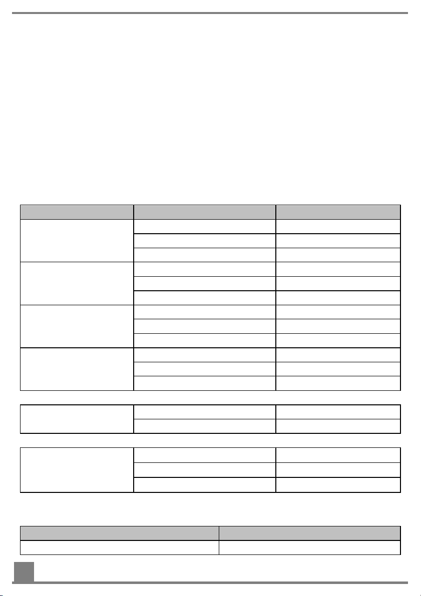
The pneumatic seeder (PS) is available in different versions. These differ in terms of
the capacity of the seed hopper (120 l, 200 l, 300 l, 500 l) and the possible types of
spreading material (seed, fertiliser).
The following versions of the pneumatic seeder are available:
•
PS 120 M1, PS 120 M1 D, PS 120 M1 MG
•
PS 200 M1, PS 200 M1 D, PS 200 M1 MG
•
PS 300 M1, PS 300 M1 D, PS 300 M1 MG
•
PS 500 M2, PS 500 M2 D, PS 500 M2 MG
•
HG 300 M1
2.4 Technical data
Mechanical data
Implement version Size Value
PS 120 M1 (D/MG) Max. tank content 120 l
Weight 45 kg
Dimensions (H × W × D in cm) 90 x 60 x 80
PS 200 M1 (D/MG) Max. tank content 200 l
Weight 60 kg
Dimensions (H × W × D in cm) 100 × 70 × 90
PS 300 M1 (D/MG) Max. tank content 300 l
Weight 70 kg
Dimensions (H × W × D in cm) 110 × 80 × 100
PS 500 M2 (D/MG) Max. tank content 500 l
Weight 93 kg
Dimensions (H × W × D in cm) 125 × 80 × 120
Hydraulic fan (HF) Weight 23 kg
Dimensions (H × W × D in cm) 27 × 46 × 40
Hydraulic lines Length of the pressure line 6 m
Length of the motor line < 1 m
Length of the tank line 6 m
Electrical data
Values for supply from the electric fan:
Size Value
Supply voltage 12 V
10
Page 11

Size Value
Supply current 25 A
Power consumption of the electric fan 25 A when starting
Hydraulic data
Values for supply from the hydraulic fan:
Size Value
Maximum pressure 180 bar
Maximum oil quantity 38 l/min
Spreading widths
Recommended spreading width: 1 - 6 m
Maximum spreading widths:
Drive type Maximum spreading width
Electric fan 6 m
Hydraulic fan 12 m (with 16 outlets)
PTO shaft blower fan 12 m (with 16 outlets)
Mounting categories
CAT I – III (only with three-point linkage)
3 Safety
This section contains all requirements and measures that ensure safe operation of
the seed drill.
3.1 Safety instructions in this document
What are safety instructions?
Safety instructions are information that serve to prevent personal injuries. Safety instructions contain the following information:
• Type of danger
• Possible consequences in case of non-compliance with the instructions
• Measures to prevent personal injury
3.2 Basic safety regulations
Target group for these regulations
These regulations are aimed at all those who will be handling the seed drill.
11
Page 12

Purpose of these regulations
These regulations aim to ensure that all persons who will be handling the seed drill
are thoroughly informed about the dangers and safety measures and observe the
safety instructions in the operating manual and on the seed drill. If you do not follow
these regulations, you are at risk of injury and material damage.
Handling the operating manual
Observe the following regulations:
• Read the Safety section and the section relating to your work completely. You
must understand these contents.
• Always keep the operating manual close to the seed drill for reference purposes.
There is a container for this installed on the seed drill.
• When passing on the seed drill, be sure to pass on the operating manual.
Handling the seed drill
Observe the following regulations:
• Only persons who fulfil the requirements defined in this operating manual may
handle the seed drill.
• Only use the seed drill for the intended purpose.
• Never use the seed drill for other purposes that may seem similar.
• Observe all of the safety measures that are indicated in this operating manual
and on the seed drill.
• Do not make any modifications to the seed drill, e.g. by removing parts or mount-
ing unauthorised parts.
• When replacing defective parts, only use original spare parts or standard parts
approved by the manufacturer.
Operator obligations toward the personnel
As the operator, you have to ensure the following:
• The personnel fulfils the requirements corresponding to his work.
• The personnel has read and understood this operating manual before handling
the seed drill.
• The regulations applicable in your country for safety at work are being observed.
Procedure in case of accident
The seed drill is designed and built so that the personnel can work without risk. Despite all precautions, however, unforeseeable accidents can still occur under unfavourable circumstances.
Always observe your company's guidelines regarding accidents.
More information on the subject of
Intended use of the seed drill On page 13
Personnel requirements On page 13
Dangers and safety measures On page 17
12
Page 13
•
•
•
3.3 Intended use
The pneumatic seeders of types PS 120 to PS 500 serve to spread seed with different properties and grain sizes on open fields.
The implements are designed solely for normal use in agricultural operations. Only
cereal varieties that are intended by the manufacturer and listed in the operating manual may be used. Different seeding shafts are designed for the different cereal varieties, which must be used and replaced if necessary. A special version of the seed drill
protected against corrosion can also be used for spreading fertiliser with a seeding
shaft designed for this purpose (intended use).
Any other use is considered to be non-intended. The manufacturer is not liable for
any resulting damage, the operator alone bears the associated risk.
Intended use also includes compliance with the conditions for operation, maintenance, and repairs prescribed by the manufacturer.
The applicable accident prevention regulations as well as the other general safety-related and occupational health regulations must also be observed.
The manufacturer is not liable for any damage resulting from unauthorised modifications and the use of components and auxiliary parts.
3.4 Personnel requirements
The implement may only be used, maintained and repaired by persons who have relevant experience and were instructed on the risks. The safety instructions must also
be handed over to other users.
Qualification
Persons who will be handling the seed drill must fulfil the following requirements:
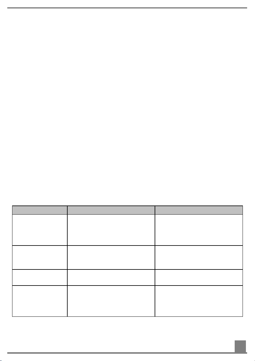
Personnel Activities Required qualification
Forwarder
Transporter
Installer
Setter
•
Transport of the seed drill
from one business to another
•
Transport of the implement
within the farm
•
Installation and commissioning of the seed drill
•
Setting up the seed drill
Experience with transport
of machinery
•
Qualification of a transport
specialist for machinery
Forklift driver
•
Experience with handling
the suitable lifting gear
•
Trained mechanic
Experience in the agricultural field
•
Experience with handling
the seed drill
13
Page 14

•
•
•
Personnel Activities Required qualification
Operator
•
Operating the seed drill on
•
Trained assistant
the farm
Cleaning the seed drill
Maintenance personnel
•
Performing maintenance
work
•
Trained mechanic
Performing repair work
Disposer
Disposal of the seed drill
•
Disposal specialist
3.5 Personal protective equipment
The personnel must be equipped with the following personal protective equipment
and wear it if necessary:
• Hearing protection
• Mask
• Safety shoes with non-slip soles
3.6 Safety devices
Meaning of the safety devices
The seed drill has safety devices that protect the user from danger. All safety devices
must be equipped and functional when operating the seed drill.
Location of the guards
The picture shows the location of the safety devices:
Function of the safety devices
The safety devices have the following function:
14
Page 15
No. Designation Function
1 Bearing cover Protection against reaching into the running agitator.
Purpose
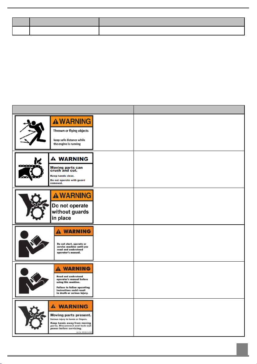
Warning signs on the seed drill warn about danger points. The warning signs must always be present and legible.
Overview
The table shows all warning signs that are installed on the seed drill and their meaning.
Appearance of the sign Meaning of the sign
Risk of injury due to thrown parts!
Maintain a safe distance from the implement during operation.
Risk of injury due to moving parts!
Only work with mounted covers.
Risk of injury due to rotating parts!
Only operate the implement when the
cover is installed.
Read and observe the operating manual before operating the implement!
Read and observe the operating manual before working with the implement!
Operating errors can lead to serious injuries.
Risk of injury due to rotating parts!
Do not reach into rotating parts.
When working on the implement,
switch these off and disconnect from
the power supply.
15
Page 16

Appearance of the sign Meaning of the sign
Be careful with escaping high-pressure
liquids!
Use hearing protection!
Hot surface!
Do not touch!
Maintain a safe distance from hot surfaces!
Risk of injury due to rotating parts!
Maintain a safe distance from rotating
parts.
Risk of injury due to rotating parts!
When the implement is running, keep
the guards closed.
Use hearing protection!
16
Page 17

3.7 Dangers and safety measures
Overview
The seed drill is designed such that the user is protected from all avoidable dangers
that are practical in design terms. Due to the purpose of the seed drill, however, there
are residual dangers that require precautionary measures to be avoided.
In the following, you will be informed about the types of these residual dangers and
their effects.
Transport
Danger Where and in which sit-
uations does the danger occur?
Risk of crushing due to
the weight of the implement
Installation
Danger Where and in which sit-
Risk of crushing due to
the weight of the implement
Risk of slipping, stumbling and falling
When lifting and lowering
the implement
uations does the danger occur?
When lifting and lowering
the implement
When mounting the implement on a soil tillage
implement or on the tractor
Countermeasure
The implement may only be
transported by personnel
trained for this task.
Countermeasure
The implement may only be
transported with a forklift or lift
truck by personnel trained for
this task.
Work must be performed on
sturdy steps with non-slip
safety shoes.
Set-up
Danger Where and in which sit-
uations does the danger occur?
Risk of injury due to
moving parts
Risk of injury due to
moving parts when the
implement is accidentally switched on
When setting the spread
rate, which must be done
with the seeding shaft
cover removed
When the agitator is activated, which must be
done with the seeding
shaft cover removed
Countermeasure
The spread rate may only be
adjusted exactly according to
the operating manual by trained
personnel.
Make sure that the implement
is disconnected from the power
supply to prevent sudden startup of the implement.
17
Page 18
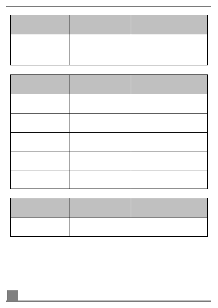
Danger Where and in which sit-
uations does the danger occur?
Danger due to defective
implement parts
When operating the implement
Operation
Danger Where and in which sit-
uations does the danger occur?
Risk of injury due to rotating parts
Risk of injury due to
When handling the implement during operation
While spreading seed. Always ensure that there is no-
seed being thrown out
Risk of slipping, stumbling and falling
Hearing damage due to
implement noise
When handling the implement during operation
When operating the implement
Countermeasure
Before operating the implement, always check for fractures, cracks, chafe marks,
leaks, loose bolts, vibrations,
sounds and function.
Countermeasure
Make sure that the covers for
the agitator are closed during
operation.
body standing in the spreading
range of the implement.
Only enter the implement area
using sturdy steps with non-slip
safety shoes.
Use hearing protection.
Risk of poisoning due to
While spreading seed. Wear a mask when handling
toxic seed types
Cleaning
Danger Where and in which sit-
uations does the danger occur?
Risk of poisoning with
toxic seed types
When cleaning the implement with compressed
air
18
toxic seed types.
Countermeasure
Wear a mask when handling
toxic seed types.
Page 19

Maintenance and repairs
Danger Where and in which sit-
Countermeasure
uations does the danger occur?
Incorrectly or inadequately performed
maintenance work with
Under poor light conditions
If necessary, maintenance must
be performed with additional
lighting.
limited visibility
4 Transport, installation and commissioning
In this section, you will learn which work steps must be performed for the installation
and commissioning of the seed drill, and what must be done and observed.
4.1 Attaching the seed drill to a soil tillage implement
Purpose
For operation on the field, the seed drill can be attached to a soil tillage implement,
such as a cultivator or a harrow. The attachment must be installed individually.
Requirements
The following requirement must be fulfilled for this work step:
• The implement is disconnected from the power source, see Disconnecting the
seed drill from the power source On page 40.
Required components, tools and materials
For this work step, the following components, tools and materials are required:
Counter plate
Bolts with Ø > 10 mm, strength class 8.8 or higher
Self-locking fastenings (nuts)
Lifting gear that is suitable for the respective implement version, see Technical
Data On page 10 for more information.
19
Page 20

Overview
No. Designation
1 Counter plate
2 Seed drill
3 Soil tillage implement
Procedure
To attach the seed drill on a soil tillage implement:
Step Description
1 Fasten the counter plate (1) on the soil tillage implement (3).
The counter plate must be parallel to the ground.
2 Use the lifting gear to place the seeder (2) on the counter plate (1).
3 Fasten the seeder (2) with bolts and nuts on the counter plate (3).
4.2 Attaching the seed drill to a tractor
Purpose
For operation on the field, the seed drill can be attached directly to a tractor.
Requirements
The following requirement must be fulfilled for this work step:
• The implement is disconnected from the power source, see Disconnecting the
seed drill from the power source On page 40.
20
Page 21

Required components, tools and materials
For this work step, the following components, tools and materials are required:
Suitable component for attachment (e.g. top link mounting kit, pallet fork or three-
point loader)
Bolts M 12, strength class 8.8 or higher
Self-locking fastenings (nuts)
• Lifting gear that is suitable for the mass of the respective implement version, see
Technical Data On page 10 for more information
Overview
No. Designation
1 Top link mounting kit
2 Seed drill
Procedure
To attach the seed drill to a tractor using the top link mounting kit:
Step Description
1 Fasten the top link mounting kit (1) with bolts and nuts onto the seed drill
(2).
2 Fasten the top link (1) with the bolts onto the tractor.
3 Using lifting gear, move the seed drill (2) close to the tractor and mount the
top link in the top link bracket. Using the counter plate, clamp the seeder
onto the tractor linkage drawbar.
4.3 Installing the dispersion plates on the soil tillage
implement
Purpose
The dispersion plates serve to fix the hoses, through which the spreading material
flows, at the right spot and spread the seed.
21
Page 22
Requirements
The following requirement must be fulfilled for this work step:
• None
Required components, tools and materials
For this work step, the following components, tools and materials are required:
Dispersion plates
Hexagon shaft
Bolts
Washers
Pliers
Hexagon key
Procedure for mounting with hexagon shaft
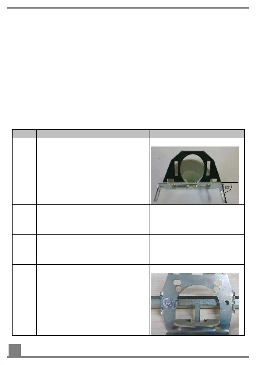
This is how to install the dispersion plates on the soil tillage implement.
Step Description Explanation/illustration
1 Using the pliers, bend the tabs on the
sides of the dispersion plates down by
80°.
Result:
2 Distribute the dispersion plates evenly
across the entire working width of the
soil tillage implement. Maximum spacing of the dispersion plates: 75 cm
3 Push the hexagon shaft through the two
hexagonal holes in the tabs on the
sides of the dispersion plate intended
for this purpose.
4 Using the supplied bolts and washers,
fasten the dispersion plates onto the
hexagon shaft.
22
Result:
Page 23

Step Description Explanation/illustration
5 Fasten the hexagon shaft equipped with
the dispersion plates onto the soil tillage
implement at a distance of 40 cm from
the ground.
6 Connect the hoses to the dispersion
plates, see Connecting the hoses On
page 23 for more information.
4.4 Connecting the hoses
Purpose
The hoses convey the seed from the seed drill onto the field. Before initial operation,
the hoses have to be cut to the required length and installed on the dispersion plates
and the seed drill.
Requirements
The following requirement must be fulfilled for this work step:
• None
Required components, tools and materials
For this work step, the following components, tools and materials are required:
Hose roll
Cutting tool
Hexagon key WAF17 or Torx screwdriver TX 25
Silicone spray
Procedure
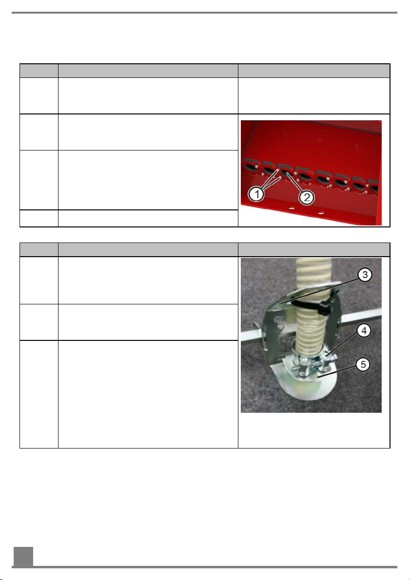
This is how you connect the hoses to the seed drill:
Version 1 (Standard PS and MG):
Step Description Illustration
1 Using the cutting tool, cut eight pieces
from the hose roll in the respectively required lengths.
2 Slightly loosen the clamping screws (1)
on the clamping plate with a WAF17
hexagon key.
3 Insert the ends of the hoses into the
transition pieces (2) up to the stop.
NOTE: If it is too difficult to insert the
hoses, use silicone spray on the outside
of the hose.
4 Tighten the clamping screws (1).
23
Page 24
Version 2 (fertiliser, 16 outlets):
Step Description Illustration
1 Using the cutting tool, cut off pieces
from the hose roll in the required length
for each transition piece.
2 Slightly loosen the clamping screws (1)
on the clamping plate using a Torx
screwdriver.
3 Insert the ends of the hoses into the
transition pieces (2) up to the stop.
NOTE: If it is too difficult to insert the
hoses, use silicone spray on the outside
of the hose.
4 Tighten the clamping screws (1).
This is how to connect the hoses to the soil tillage implement and dispersion plates:
Step Description Illustration
1 Insert the ends of the hose through the
openings in the large tab (3) of the dispersion plate and slide the fastening clip
(4) onto the hose.
2 Push the end of the hose through the
opening in the small tab (5) on the dispersion plate.
3 Install the fastening clip (4) on the dis-
persion plate (5).
In doing so, install the fastening clip so
that
•
the holding finger is positioned between the hose and the fastening
clip.
•
it is fixed by the hooks on the holding finger.
4.5 Removing the swell air plate
Purpose
The swell air plate guides the air from the fan over the seeding shaft. With coarse
seed types such as vetch, peas or horse gram, the swell air plate must be removed to
24
Page 25

prevent damage to the seeding shaft. In addition, a flex seeding shaft must be used
for coarse seed types to prevent damage to the seeding shaft or the seed.
Requirements
The following requirements must be fulfilled for this work step:
• The implement is disconnected from the power source, see Disconnecting the
seed drill from the power source On page 40.
Required components, tools and materials
For this work step, the following components, tools and materials are required:
Hexagon key
Torx screwdriver TX 30
Procedure
This is how you remove the swell air plate:
Step Description Explanation
1 Loosen the hexagonal bolt (2) on the
calibration slide (1).
2 Remove the calibration slide.
3 Loosen the Torx screws (3) and remove
the swell air plate (4).
4.6 Connecting the hydraulic fan (HF)
Purpose
The hydraulic fan is used for operation with working widths up to 12 m or for higher
spread rates of e.g. wheat.
25
Page 26

Requirements
The following requirement must be fulfilled for this work step:
• The hydraulic system is depressurized both on the tractor and implement side.
Required components, tools and materials
For this work step, the following components, tools and materials are required:
• Coupling connector or coupling sleeve (for initial operation)
Overview
No. Designation
1 Hydraulic block
2 Flow control valve
3 Coupling sleeve (alternative)
4 Coupling connector
5 Return line
6 Pressure line
Procedure
This is how to connect the hydraulic fan:
Step Description
1 Completely close the flow control valve (2) on the hydraulic block (1).
2 Connect the return line (5) (marked in yellow, BG4) without reduction to the
return flow connection of the tractor hydraulic system.
For initial operation: Remove the plastic plug on the return line and connect
the coupling plug (4) or the coupling sleeve (3) with the return line.
3 Connect the pressure line (6) (marked in red, BG3) with a pressure con-
nection of the tractor hydraulic system.
26
Page 27

5 Operation
In this section, you will learn how to properly configure the seed drill and the seed
flow rate, and how to adjust it during operation.
5.1 Setting the hydraulic fan (HF)
Purpose
The hydraulic fan produces an air current that carries the seed through the hoses to
the dispersion plates.
The required air pressure and air quantity depend strongly on the seed (type and
weight), the spread rate, working width and speed. For this reason, it is not possible
to give precise specifications for the correct fan settings, it must be determined in field
trials! Reference values for the fan setting can be found in the setting table for the
flow control valve.
Requirements
The following requirement must be fulfilled for this work step:
• The hydraulic fan is connected, see also Connecting the hydraulic fan (HF) On
page 25.
Required components, tools and materials
For this work step, the following components, tools and materials are required:
• None
Overview
No. Designation
1 Hydraulic block
2 Flow control valve
27
Page 28
Procedure
This is how to set the hydraulic fan:
Version 1 (Constant pump – non-adjustable oil quantity on the tractor)
Step Description
1 Completely close the flow control valve (2) on the hydraulic block (1).
2 Start up the blower fan (tractor engine speed as in field operation).
3 Adjust the fan speed using the flow control valve (2) on the control block.
Version 2 (Variable pump - oil quantity adjustable on the tractor):
Step Description
1 Completely open the flow control valve (2) on the hydraulic block (1).
2 Completely close the flow control valve on the tractor (set the oil quantity to
zero).
3 Start up the fan and run up to the desired fan speed (slowly increase the oil
quantity).
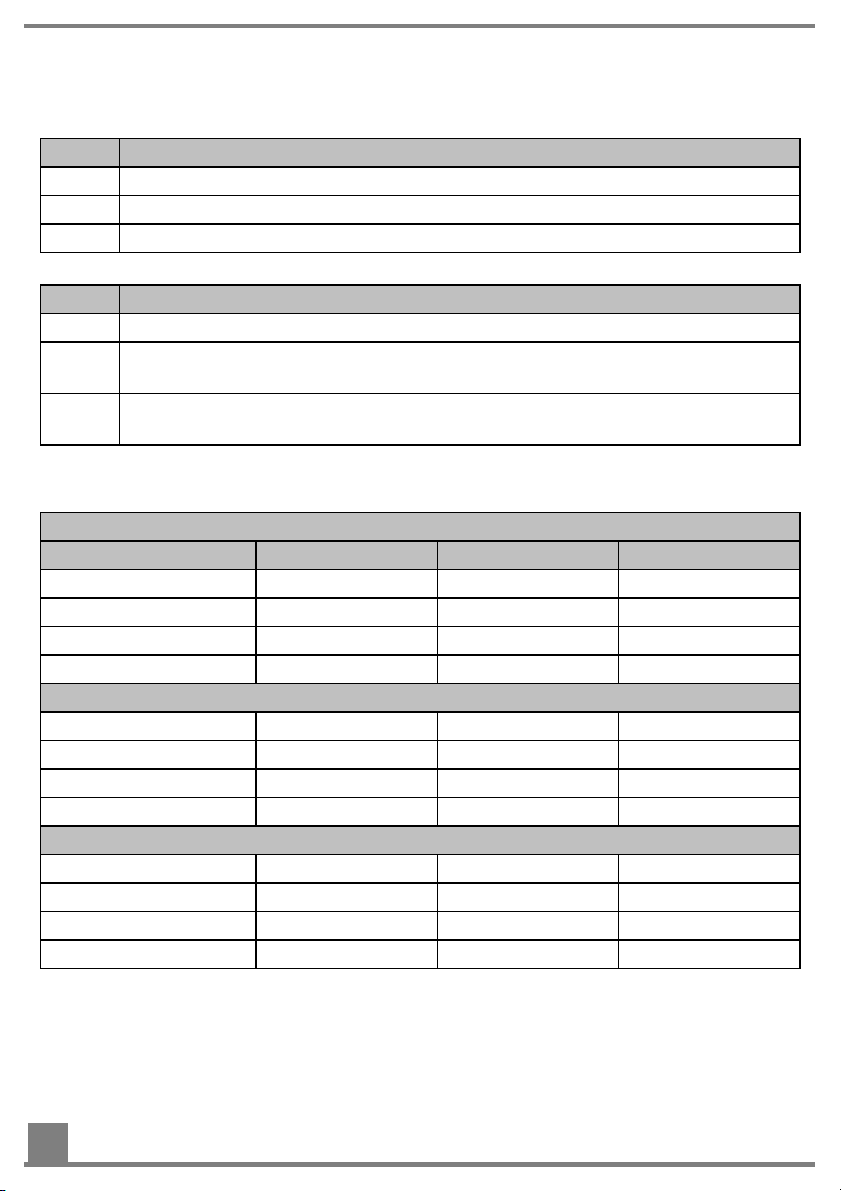
Setting table for the flow control valve
(valid for approx. 50°C oil temperature)
Working width 3 m
Seed Rate Pressure Speed
Fine seed 5 kg/ha 5 bar 1400 rpm
Fine seed 30 kg/ha 15 bar 2900 rpm
Coarse seed 50 kg/ha 18 bar 3000 rpm
Coarse seed 100 kg/ha 19 bar 3100 rpm
Working width 6 m
Fine seed 5 kg/ha 8 bar 1550 rpm
Fine seed 30 kg/ha 20 bar 3300 rpm
Coarse seed 50 kg/ha 21 bar 3400 rpm
Coarse seed 100 kg/ha 22 bar 3500 rpm
Working width 12 m
Fine seed 5 kg/ha 10 bar 1650 rpm
Fine seed 30 kg/ha 35 bar 4000 rpm
Coarse seed 50 kg/ha 39 bar 4200 rpm
Coarse seed 100 kg/ha 41 bar 4300 rpm
28
Page 29

5.2 Setting and adjusting the spread rate
Purpose
The setting for the spread rate, which is spread by the seed drill during the seeding
process, has a significant effect on the seeding results.
Requirements
The following requirement must be fulfilled for this work step:
• None
Procedure
This is how to set and adjust the spread rate:
Step Description
1 Perform a calibration test to determine the current spread rate, see Per-
forming a calibration test On page 30 for more information.
2 If necessary, take measures to adjust the spread rate.
Suitable measures are:
•
Selection of the seeding shaft, see Selecting the right seeding shaft
On page 31 for more information.
•
Selection of the brush pressure, see Setting the brush pressure On
page 35 for more information.
•
Adjustment of the working width, see Installing dispersion plates on
the soil tillage implement On page 21 for more information.
•
Adjusting the tractor speed.
Calculating the spread rate
The spread rate can be calculated using the following formula:
SpR: spread rate in kg/min
m(wgt): desired spread rate in kg/ha
v(tractor): speed of the tractor in km/h
w(working): working width in m
29
Page 30

5.3 Regulating the seed flow rate (calibration test)
Purpose
During the calibration test, the seed quantity for a specific area is defined.
Requirements
The following requirement must be fulfilled for this work step:
• The implement is disconnected from the power source, see Disconnecting the
seed drill from the power source On page 40.
Required components, tools and materials
For this work step, the following components, tools and materials are required:
Calibration bag
Hexagon key
Procedure
This is how to perform a calibration test:
Step Description Explanation
1 Loosen the hexagonal bolt (2) on the
calibration slide (1).
2 Take the calibration slide out of the an-
choring and turn it by 180°.
3 Attach the rotated calibration slide back
onto the seeder.
4 Hook the calibration bag onto the cali-
bration slide.
5 Select a suitable brush pressure, see
Setting the brush pressure On page
35.
30
Result:
Page 31
•
•
•
Step Description Explanation
6 Switch on the control box.
7 Start the calibration program of the
seed drill, refer to the control box operating manual for more information.
5.4 Selecting the right seeding shaft
Purpose
By selecting the right seeding shaft, which is suitable for the seed type, the seeding
results are significantly improved.
Requirements
The following requirement must be fulfilled for this work step:
• None
Required components, tools and materials
For this work step, the following components, tools and materials are required:
• None
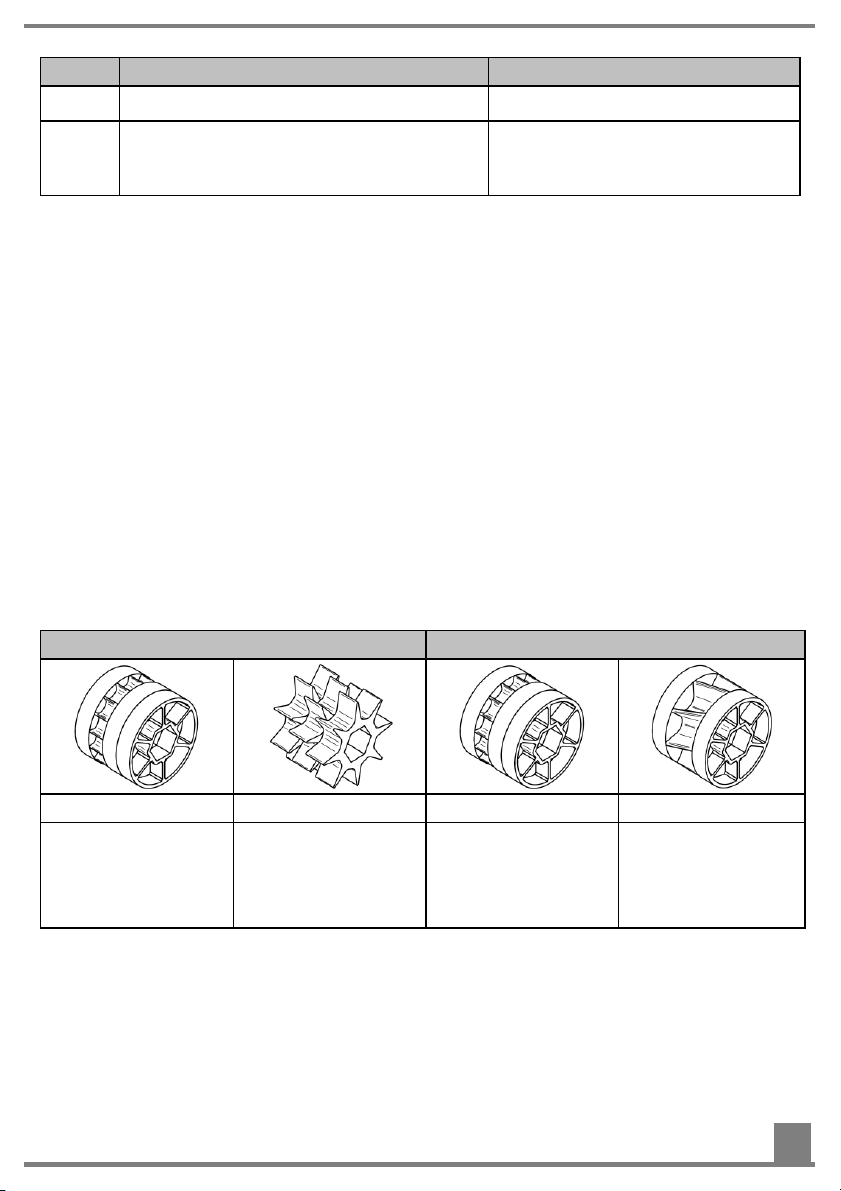
Table of available seeding shafts
From the following tables, select the seeding shaft that is suitable for your purposes:
Standard equipment D series standard equipment
fb-f-fb-fb GGG fb-f-fb-fb fb-Flex20-fb
•
Grass
Cereals
•
Mustard
•
Phacelia
Micro granules
fertiliser
•
Mustard
•
Phacelia
Micro granules
fertiliser
•
Peas
•
Beans
31
Page 32

•
•
•
•
•
•
•
Available as an option
fb-fb-ef-eb-fb fb-efv-efv-fb ffff GB-G-GB
•
Poppy
Available as an option
fb-Flex20-fb Flex40 fb-fv-fv-fb
•
Peas
•
Beans
•
Lupines
•
Vetch
Fertiliser
Oil rape seed
Peas
•
Beans
•
Lupines
•
Vetch
•
Fertiliser
Buckwheat
•
Mustard
Cress
Clover
•
Cress
Buckwheat
•
Fodder radish
CAUTION! It is important to select the combination of seed wheels such that
the seeding shaft settings on the control box are ideally between 20 % and
80 %. This ensures good regulation and homogeneous delivery of the seed
even with ground speed related spreading at very low or high speeds!
5.5 Changing the seeding shaft
Purpose
By installing the right seeding shaft, the seeding results are significantly improved.
Requirements
The following requirements must be fulfilled for this work step:
• The implement is disconnected from the power source, see Disconnecting the
seed drill from the power source On page 40.
• The seed tank is empty, see Emptying the seed tank On page 41 for more infor-
mation.
32
Page 33

• The right seeding shaft is selected and ready, see Selecting the right seeding
shaft On page 31 for more information.
Required components, tools and materials
For this work step, the following components, tools and materials are required:
Hexagon key
Overview
Access to the agitator drive and the required tool:
No. Designation
1 Bearing cover
2 Hexagon key holder
3 Cover nuts
4 Drive belt
5 Bearing flange
6 Knurled nuts
Procedure
This is how to change the seeding shaft:
Step Description Explanation
1 Take the hexagon key from the holder
(2).
2 Loosen the cover nuts (3) on the bear-
ing cover (1).
33
Page 34

Step Description Explanation
3 Remove the bearing cover (1).
4 Remove the drive belt (4).
5 Loosen the knurled nuts (6).
6 Remove the bearing flange (5). Result:
7 Take out the seeding shaft.
NOTE: Residual seed can fall out in the
process.
8 Insert the new seeding shaft with the
free journal forwards into the steel
frame.
9 Turn the seeding shaft until the fitted
key of the gearbox motor engages in
the groove of the seeding shaft.
10 Fit the bearing flange with its fitted key
into the fitted groove of the seeding
shaft.
11 Hand-tighten the knurled nuts on the
bearing flange.
12 Place the drive belt over the two gear
wheels.
13 Fit the bearing cover on the two
threaded rods and tighten the cover
nuts with the hexagon key.
34
Page 35

Step Description Explanation
14 Check the seeding shaft for ease of mo-
tion, see Checking the ease of motion
of the shaft On page 35 for more information.
5.6 Checking the ease of motion of the seeding shaft
Purpose
Each time the seeding shaft is installed or replaced, it must be checked for ease of
motion. This check is performed by a hearing test.
Requirements
The following requirement must be fulfilled for this work step:
• The seed tank is empty, see Emptying the seed tank On page 41 for more infor-
mation.
Required components, tools and materials
For this work step, the following components, tools and materials are required:
None
Procedure
This is how to check the ease of motion of the seeding shaft:
Step Description
1 Switch on the seed drill.
2 Perform the hearing test.
3 If the sound of the running seeding shaft is noticeably loud or irregular,
contact the maintenance and repair service, see Contact service On page
5 for more information.
5.7 Setting the brush pressure
Purpose
The brush pressure on the seeding shaft is regulated using the brush adjustment
lever.
Requirements
The following requirement must be fulfilled for this work step:
• None
35
Page 36

Required components, tools and materials
For this work step, you need the following components, tools and materials:
• None
Overview
No. Designation
1 Brush adjustment lever
2 Setting scale
Procedure
This is how to set the brush pressure:
Step Description
1 Pull the brush adjustment lever (1) out of the setting scale.
2 Move the brush lever to the desired position and engage it in the appropri-
ate notch of the setting scale.
The following orientation rules apply here:
•
For fine seed, increase the brush pressure up to -5.
•
For coarse seed, reduce the brush pressure up to +4.
5.8 Filling the seed tank
Purpose
The seed tank stores the seed to be spread.
Requirements
The following requirement must be fulfilled for this work step:
• The implement is disconnected from the power source, see Disconnecting the
seed drill from the power source On page 40.
Required components, tools and materials
For this work step, the following components, tools and materials are required:
Seed
36
Page 37

Overview
No. Designation
1 Seed tank cover
2 Seed tank
Procedure
This is how to fill the seed tank:
Step Description Explanation
1 To open the seed tank, turn the cover
(1) counterclockwise.
2 Fill the seed into the seed tank (2).
3 To close the seed tank, turn the cover
(1) clockwise.
5.9 Deactivating the agitator
Purpose
Use of the agitator is only required for seed types that tend towards bridging or for
very light seed (e.g. for grasses).
Requirements
The following requirements must be fulfilled for this work step:
• The implement is disconnected from the power source, see Disconnecting the
seed drill from the power source On page 40.
37
Page 38

Required components, tools and materials
For this work step, the following components, tools and materials are required:
Hexagon key
Drive belt
Overview
No. Designation
1 Bearing cover
2 Hexagon key holder
3 Cover nuts
4 Agitator
5 Seeding shaft
Procedure
This is how to deactivate the agitator:
Step Description Explanation
1 Open the bearing cover (1).
To do so, loosen the cover nuts (3) with
the hexagon key.
38
Page 39
•
•
Step Description Explanation
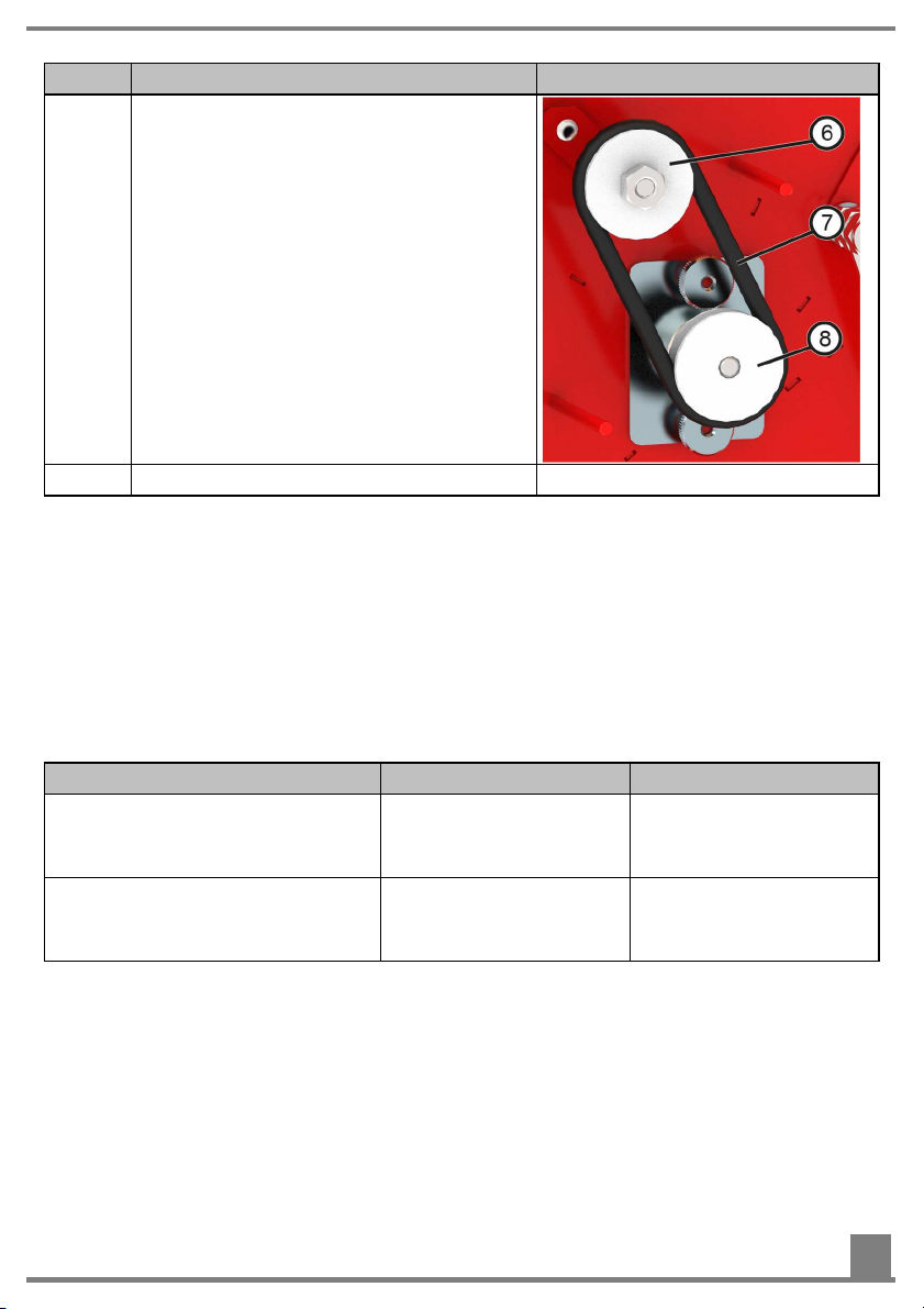
2 Release the drive belt (7) from the
seeding shaft driving wheel (8) and the
agitator driving wheel (6) and put it
aside.
3 Close the bearing cover (1).
6 Faults
In this section, you will find information for eliminating faults that may occur during operation.
6.1 Fault overview
Problem Cause Remedy
The seeding shaft does not rotate when the drive shaft of the
gearbox motor is rotating
The seed hoses get clogged
You can find more information on other faults in the operating manuals for the respective control boxes.
If the problem could not be fixed, please contact the manufacturer. You can find information for this under Contact Service On page 5.
•
The fitted key fell
out of the drive
shaft
•
Fan speed is too
low
Stick on a new fitted key
Check the fan
speed and increase
if necessary
39
Page 40

7 Cleaning, maintenance, and repairs
In this section, you will learn how to clean and maintain the seed drill, and what to do
in case of damage or failure of the implement.
7.1 Disconnecting the seed drill from the power supply
Purpose
Setup and maintenance work often require that the seed drill is disconnected from the
power supply.
Requirements
The following requirements must be fulfilled for this work step:
• None
Required components, tools and materials
For this work step, the following components, tools and materials are required:
• None
Overview
No. Designation
1 Implement cable
2 Main plug of the implement cable
Procedure
This is how to disconnect the seed drill from the power supply:
40
Page 41

Step Description
1 Pull out the power supply plug from the control box
or
Pull out the implement cable plug from the control box
or
Switch off the control box
7.2 Emptying the seed tank
Purpose
Before cleaning or decommissioning, the seed remaining in the seed drill must be removed from the seed tank.
Requirements
The following requirement must be fulfilled for this work step:
• The implement is disconnected from the power source, see Disconnecting the
seed drill from the power source On page 40.
Required components, tools and materials
For this work step, the following components, tools and materials are required:
• None
Procedure
This is how to empty the seed tank:
Step Description Explanation
1 Loosen the hexagonal bolt (2) on the
calibration slide (1).
NOTE: The bolts are connected to the
calibration slide with the locking rings.
2 Take the calibration slide out of the an-
choring and turn it by 180°.
3 Attach the rotated calibration slide back
onto the seeder.
4 Start the emptying program of the con-
trol box, refer to the control box operating manual for more information.
41
Page 42

7.3 Cleaning the seed drill
Purpose
The seed drill must be cleaned inside and out on a regular basis to ensure long-term
proper functioning. If not cleaned properly, germs can form inside the seed drill due to
seed residues.
Requirements
The following requirements must be fulfilled for this work step:
• The implement is disconnected from the power source, see Disconnecting the
seed drill from the power source On page 40.
Required components, tools and materials
For this work step, the following components, tools and materials are required:
• Air compressor
• Moist cloth
Procedure
To clean the seed drill:
Step Description Explanation
1 Empty the seed tank, see Emptying
the seed tank On page 41 for more in-
formation.
2 Remove the seeding shaft, see Chang-
ing the seeding shaft for more information.
3 Turn the seed tank cover counterclock-
wise to open it.
4 Clean the inside of the seed drill and
the seed paths with compressed air.
5 Clean the outside of the seed drill with a
moist cloth.
42
Page 43

7.4 Checking the hydraulic hoses
Have the hydraulic hoses checked annually by a qualified technician. The inspection
intervals to be observed may be regulated by regional laws and regulations.
According to DIN 20066, all hydraulic hoses must be replaced after 6 years at the latest.
7.5 Repairs and service
In case of failure or damage to the seed drill, please contact the manufacturer. You
can find information for this under Contact Service On page 5.
8 Decommissioning, storage and disposal
In this section, you will learn how to decommission the seed drill, store it for longer
periods of time, and dispose of it.
8.1 Decommissioning the seed drill
Purpose
To ensure that the seed drill remains fully functional even if it is out of operation for
longer periods of time, it is important to take precautions for storage.
Procedure
This is how to prepare the seed drill for storage:
Step Description
1 Completely remove all seed from the seed drill.
2 Clean the seed drill inside and out, see Cleaning the seed drill On page
42 for more information.
3 Set the brush adjustment lever to Position "+4".
4 Store the seed drill in a dry place to prevent the formation of germs inside
the implement.
8.2 Storage of the seed drill
The seed drill must be stored in a dry place protected from weather conditions to ensure that it remains functional even if it is stored for a longer period of time.
8.3 Disposal
Disposal of the seed drill must be performed according to the local disposal regulations for machines.
43
Page 44

9 Accessories
In this section, you will find a selection of possible accessories for your implement.
9.1 HG 300 M1
The HG 300 M1 is a hydraulically driven radial
fan for working widths up to 12 m or for higher
spread rates for e.g. wheat.
It is very resistant to dust and foreign objects,
since these do not easily accumulate.
For mounting on the PS 120/200/300 M1 and PS
500 M2, a complete mounting kit including a transition piece and brace is available.
Scope of delivery:
1 HG 300 M1
1 Support
1 Flow regulator incl. hydraulic hoses
Order number:
Item no.: 08001-2-044
9.2 Fill level sensor
This sensor can be retrofitted on the
PS 120/200/300 M1.
Operation with a control box 1.2, 5.2 or 6.2 is required.
It measures how much seed is still left in the hopper, and triggers an alarm on the control box
when there is not enough seed in the hopper.
The intensity of the sensor can also be adjusted
for the respective seed type. It is adjusted using
the small slotted screw at the rear of the sensor.
Scope of delivery:
1 Fill level sensor
1 Assembly plate
Order number:
Item no. 04000-2-269
44
Page 45
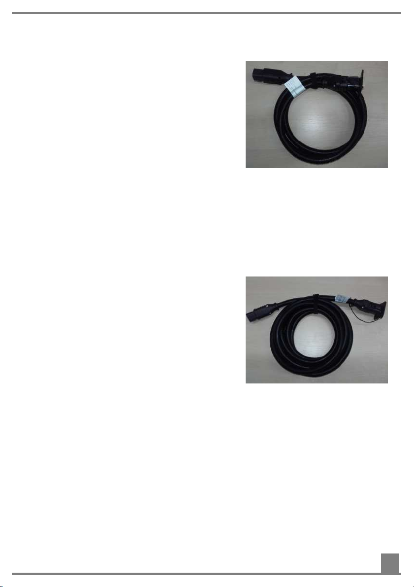
9.3 Cable extension 2 m (6-pin)
If the standard installed 6 m implement cable is
too short due to the length of the soil tillage implement or how the implement is mounted, or if
the cable cannot be routed practically, this 2 m
cable extension can be ordered as an accessory.
Scope of delivery:
1 Cable extension
Order number:
Item no.: 00410-2-148
9.4 Cable extension 5 m (6-pin)
If the standard installed 6 m implement cable is
too short due to the length of the soil tillage implement or how the implement is mounted, or if
the cable cannot be routed practically, this 5 m
cable extension can be ordered as an accessory.
Scope of delivery:
1 Cable extension
Order number:
Item no.: 00410-2-149
45
Page 46
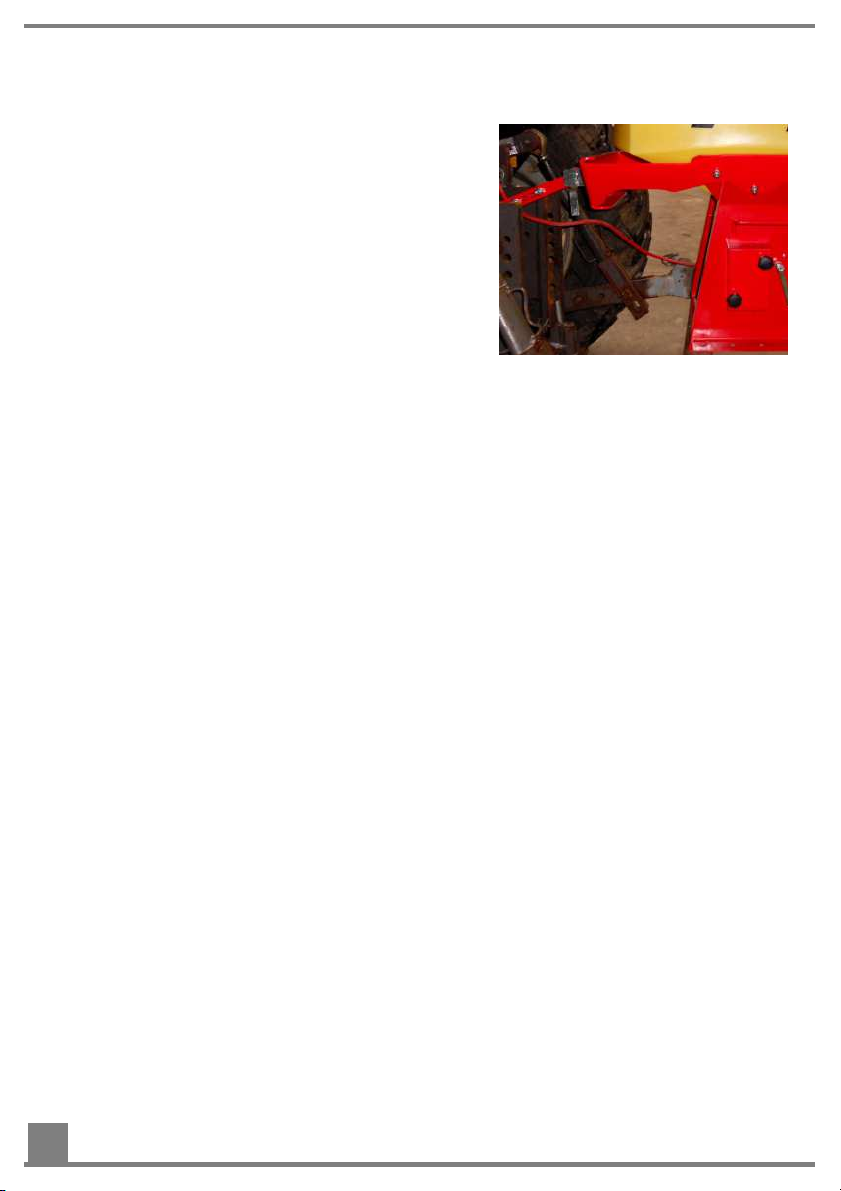
9.5 Top link mounting kit for PS 120-500
With the top link mounting kit (three-point linkage), you can attach the PS 120/200/300 M1,
PS 500 M2 to a CAT 1 – CAT 3 three-point hitch.
Scope of delivery:
1 Three-point linkage
Order number:
Item no.: 04000-2-114
10 Appendix
10.1 My idea
The PS 120/200/300 M1 (D/MG) / PS 500 M2 (D/MG) were extensively developed
and tested. It took a long time from the initial idea to serial production. It required lots
of commitment from the entire development team.
Nonetheless, the most valuable experience is gained in practice. Our motto:
"Inspired by Farmers & realized by Professionals."
This is how customer proximity of the development department creates a leading
edge for you and APV.
Tell us about the positive and negative experiences you have had with the implement.
Share your suggestions for improvement and your ideas with us:
Take pictures or make hand-drawn sketches! We are open and grateful for any information, no matter in what form.
Your information goes directly to the leading developers at APV.
I would like to thank you in advance for your involvement and wish you lots of fun with
your APV product!
Sincerely yours
Your Head of Development & Customer Service
46
Page 47

10.2 Connection diagram
47
Page 48

No. Description Colour Cross-section
(mm²)
1 Implement cable (pin 1) Blue 4.0
2 Implement cable (pin 2) brown 4.0
3 Implement cable (pin 3) Blue 1.5
4 Implement cable (pin 4) Grey 1.5
5 Implement cable (pin 5) brown 1.5
6 Implement cable (pin 6) Black 1.5
7 Seeding shaft motor Black 1.5
8 Seeding shaft motor red 1.5
9 Calibration button (optional) brown 0.75
10 Calibration button (optional) Black 0.75
11 Fan (not with HF) Blue 4.0
12 Fan (not with HF) brown 4.0
13 Fill level sensor (optional) brown 0.75
14 Fill level sensor (optional) Blue 0.75
15 Fill level sensor (optional) white 0.75
16 Fan speed sensor (optional HF) brown 0.75
17 Fan speed sensor (optional HF) Blue 0.75
18 Fan speed sensor (optional HF) Black 0.75
19 Pressure switch (only HF) Blue 1.5
20 Pressure switch (only HF) brown 1.5
21 Hydraulic switch (only HF) Black 1.5
22 Hydraulic switch (only HF) brown 1.5
48
Page 49

10.3 Hydraulic diagram
Pos. Description
A G ½" (bolted connection XGE 15 LR-ED)
Max. hose length 1 m
Motor-side connection B
B G ½" (bolted connection XGE 15 LR-ED)
Max. hose length 1 m
Motor-side connection A
49
Page 50

Pos. Description
P G ½" (bolted connection XGE 18 LR-ED)
Max. hose length 6 m
Coupling connector BG3
Marked in red
Max. flow rate 80 l/min
Max. pressure 220 bar
T G ¾" (bolted connection XGE 22 LR-ED)
Max. hose length 6 m
Coupling connector (or coupling sleeve) BG4
Marked in yellow
50
Page 51

10.4 Seeding tables
Wheat
Wheat
Blé
Triticum
Rate kg/min kg/min kg/min kg/min kg/min kg/min kg/min
Seeding
shaft
2
5
10
20
30
40
50
60
70
80
90
95
100
ffff GGG fb-Flex20-fb Flex40 ffff BG-G-BG GGG
0.13 0.52 0.34 0.48 0.06 0.26 0.27
0.16 1.18 0.58 1.03 0.22 0.45 0.61
0.20 2.30 0.99 1.95 0.49 0.76 1.17
0.28 4.52 1.79 3.78 1.03 1.39 2.30
1.58 6.70 2.59 5.61 1.38 1.98 3.42
4.11 8.82 3.39 7.44 1.55 2.54 4.55
6.63 10.94 4.19 9.27 1.72 3.11 5.67
7.28 11.48 4.99 11.10 1.93 3.50 6.79
7.93 12.03 5.80 12.93 2.13 3.89 7.92
8.58 12.57 6.60 14.76 2.34 4.28 9.05
9.23 13.12 7.40 16.59 2.54 4.67 10.17
9.86 13.93 7.80 17.51 2.67
10.48 14.75 8.20 18.42 2.81
Gras
Grass
Herbe
Lolium perenne
10.73
11.30
Page 52

Buckwheat
Buckwheat
Blé Noir
Fagopyrum
Rate kg/min kg/min kg/min kg/min kg/min kg/min kg/min
Seeding
shaft
2
5
10
20
30
40
50
60
70
80
90
95
100
ffff GGG fb-Flex20-fb Flex40 fb-f-fb-fb fb-fb-ef-eb-fb fb-efv-efv-fb
0.09 0.54 0.33 0.27 0.11 0.04 0.01
0.39 0.99 0.50 0.70 0.21 0.06 0.02
0.90 1.74 0.78 1.40 0.38 0.10 0.05
1.92 3.24 1.35 2.82 0.72 0.18 0.10
2.86 4.68 1.92 4.23 1.03 0.29 0.16
3.74 6.07 2.49 5.65 1.32 0.45 0.22
4.62 7.45 3.07 7.07 1.62 0.60 0.27
5.06
5.50
5.94
6.38
3.64 8.48 1.75 0.67 0.33
4.21 9.90 1.89 0.73 0.38
4.78 11.31 2.03 0.80 0.44
5.35 12.73 2.17 0.86 0.50
5.63 13.44 2.30 0.91 0.52
5.92 14.14 2.44 0.95 0.55
Oil rape seed
Rape
Colza
Brassica Napus
Page 53

Oats
Oats
Avoine
Avena
Rate kg/min kg/min kg/min kg/min kg/min kg/min kg/min
Seeding
shaft
2
5
10
20
30
40
50
60
70
80
90
95
100
fb-f-fb-fb GGG ffff GGG ffff GGG GGG
0.01 0.15 0.18 0.54 0.24 0.66 0.46
0.02 0.46 0.48 0.87 0.62 1.18 0.99
0.04 0.98 0.97 1.41 1.27 2.05 1.87
0.07 2.02 1.96 2.51 2.55 3.79 3.62
0.12 3.03 2.95 3.61 3.60
0.17 4.01 3.94 4.71 4.98
0.22 4.99 4.93 5.81
0.24 5.85 5.12 7.59
0.26 6.72 5.32 9.38
0.27 7.58 5.51 11.16
0.27 8.45 5.71 12.95
0.28 8.73 5.80 13.84
0.31 10.23 5.90 14.73
Barley
Barley
Orge
Hordeum
Radish
Radish
Radis
Raphanus raphanistrum
Perennial rye
Green Rye
Seigle Vert
Secale cereale
5.33
6.98
8.64
10.27
11.89
13.44
14.92
15.14
18.10
Page 54

Vetch
Vetch
Vesce
Vicia
Rate kg/min kg/min kg/min kg/min kg/min kg/min kg/min
Seeding
shaft
2
5
10
20
30
40
50
60
70
80
90
95
100
fb-f-fb-fb ffff fb-f-fb-fb ffff fb-f-fb-fb ffff GGG
0.76 3.37 0.04 0.33 0.10 0.30 0.42
1.42 3.89 0.15 0.75 0.21 0.70 1.11
2.51 4.75 0.33 1.74 0.40 1.38 2.26
4.71 6.48 0.68 2.86 0.79 2.73 4.56
8.00 1.00 4.23 1.15 4.05 6.87
Mustard
Mustard
Moutarde
Sinapis Alba
1.29 5.56 1.49 5.36 9.19
1.58 6.89 1.82 6.67 11.51
1.72 7.61 1.90 7.40 13.44
1.86 8.33 1.97 8.14 15.37
2.00 9.05 2.04 8.87 17.30
2.14 9.77 2.12 9.61 19.23
2.31 10.35 2.24 10.33 21.71
2.48 10.92 2.36 11.06 24.20
Alfalfa
Alfalfa
Alfalfa
Medicago Sativa
Blue lupine
Blue Lupine
Lupin Bleu
Lupinus angutifo-
lius
Page 55

Red clover
Red Clover
Trèfle Rouge
Trifolium
Rate kg/min kg/min kg/min kg/min kg/min kg/min kg/min
Seeding
shaft
2
5
10
20
30
40
50
60
70
80
90
95
100
fb-f-fb-fb ffff fb-f-fb-fb ffff fb-Flex20-fb Flex40 fb-fb-ef-eb-fb
0.04 0.56 0.14 0.34 0.46 0.95 0.03
0.15 1.37 0.31 0.77 0.67 1.45 0.05
0.33 2.72 0.61 1.49 1.02 2.29 0.08
0.70 5.41 1.19 2.94 1.72 3.96 0.15
1.06 6.99 1.52
1.41 7.45 1.59
1.76 7.91 1.66
1.87 8.36 1.85
1.98 8.82 2.04
2.09 9.28 2.23
2.20 9.74 2.42
2.33 10.34 2.52
2.46 10.94 2.62
Phacelia
Phacelia
Phavélie
Phacelia tanacetigolia
Pea
Pea
Pois
Pisum sativum
2.42 5.63 0.26
3.12 7.30 0.41
3.83 8.98 0.57
4.53 10.65 0.64
5.23 12.32 0.71
5.93 13.99 0.78
6.64 15.67 0.86
6.99 16.50 0.90
7.34 17.34 0.94
Poppy
Poppy
Pavot
Papaver
Page 56

Horse gram
Field beans
Féveroles
Macrotyloma uniflorum
Rate kg/min kg/min kg/min kg/min kg/min kg/min kg/min
Seeding
shaft
2
5
10
20
30
40
50
60
70
80
90
95
100
fb-Flex20-fb Flex40 fb-f-fb-fb fb-fb-ef-eb-fb fb-f-fb-fb fb-fv-fv-fb GGG
0.46 1.02 0.05 0.03 0.00 0.12 1.27
0.66 1.57 0.12 0.05 0.08 0.19 2.25
1.00 2.49 0.24 0.08 0.21 0.30 3.67
1.68 4.32 0.47 0.15 0.46 0.54 6.73
2.36 6.15
3.04 7.98
3.71 9.81
4.39 11.64
5.07 13.47
5.75 15.30
6.43 17.13
6.77 18.05
7.11 18.96
Chia WHITE
Florex Force NACKAS bulk
0.25 0.72 0.77 9.54
0.38 0.98 1.00 11.95
0.52 1.23 1.23 14.80
0.58 1.49 1.46 17.46
0.65 1.75 1.69 19.78
0.71 2.00 1.93 20.99
0.78 2.26 2.16 21.90
0.79 2.39 2.27 22.31
0.80 2.52 2.35 22.72
Page 57

DC25 bulk DC37 bulk PHYSIOSTART
Rate kg/min kg/min kg/min kg/min kg/min kg/min kg/min
Seeding
shaft
2
5
10
20
30
40
50
60
70
80
90
95
100
GGG fb-Flex20-fb Flex40 GGG fb-fv-fv-fb fb-f-fb-fb fb-Flex20-fb
0.90 0.62 1.38 0.60 0.16 0.21 0.61
1.81 0.93 2.04 1.64 0.25 0.30 0.93
3.82 1.43 3.15 3.05 0.41 0.46 1.45
6.90 2.45 5.35 6.25 0.71 0.78 2.51
10.08 3.46 7.55 9.16 1.02 1.10 3.56
13.11 4.48 9.75 12.02 1.32 1.41 4.61
16.15 5.49 11.95 14.67 1.63 1.73 5.66
18.85 6.51 14.15 16.99 1.93 2.05 6.72
22.08 7.52 16.35 19.68 2.24 2.36 7.77
23.91 8.46 18.41 21.73 2.56 2.65 8.83
25.41 8.93 19.18 22.84 2.82 2.79 9.60
26.15 9.16 19.56 23.26 2.96 2.87 9.98
26.90 9.39 19.54 23.51 3.21 2.99 10.52
Page 58

11 Index
A
F
About this operating manual • 4
Accessories • 45
Appendix • 47
Attaching the seed drill to a soil tillage
implement • 20
Attaching the seed drill to a tractor • 21
B
Basic safety regulations • 12
C
Cable extension 2 m (6-pin) • 46
Cable extension 5 m (6-pin) • 46
Calibration test • 31
Changing the seeding shaft • 33, 43
Checking the ease of motion of the
seeding shaft • 36
Checking the hydraulic hoses • 44
Cleaning the seed drill • 43, 44
Cleaning, maintenance, and repairs •
41
Connecting the hoses • 24
Connecting the hydraulic fan (HF) •
26, 28
Connection diagram • 48
D
Dangers and safety measures • 13, 17
Deactivating the agitator • 38
Decommissioning the seed drill • 44
Decommissioning, storage and
disposal • 44
Description • 7
Disconnecting the seed drill from the
power supply • 20, 21, 26, 31, 33,
37, 38, 41, 42, 43
Disposal • 44
E
EC Declaration of Conformity • 6
Emptying the seed tank • 33, 36, 42,
43
Fault overview • 40
Faults • 40
Fill level sensor • 45
Filling the seed tank • 37
G
General information • 4
H
HG 300 M1 • 45
Hydraulic diagram • 50
I
Identification of the implement • 5
Installing the dispersion plates on the
soil tillage implement • 22, 30
Intended use • 13
L
Layout and function of the hydraulic
fan (HG 300 M1) • 9
Layout and functioning of the seed drill
• 7
M
My idea • 47
O
Operation • 28
P
Personal protective equipment • 15
Personnel requirements • 13, 14
R
Regulating the seed flow rate
(calibration test) • 30, 31
Removing the swell air plate • 25
Repairs and service • 44
S
Safety • 4, 12
Safety devices • 15
Safety instructions in this document •
12
Scope of delivery • 10
58
Page 59

Seeding tables • 52
Selecting the right seeding shaft • 30,
32, 33
Service • 6, 36, 40, 44
Setting and adjusting the spread rate •
30
Setting the brush pressure • 30, 31, 36
Setting the hydraulic fan (HF) • 28
Storage of the seed drill • 44
T
Technical data • 11, 20, 21
Top link mounting kit for PS 120-500 •
47
Transport, installation and
commissioning • 20
59
Page 60

Impressum
Qualität für Profis
- seit 1997 -
APV - Technische Produkte GmbH
ZENTRALE
Dallein 15, 3753 Hötzelsdorf, Austria
Telephone: +43 (0) 2913 / 8001 Email: [email protected]
Fax: +43 (0) 2913 / 8002 Web: www.apv.at
APV – Technische Produkte GmbH, Geschäftsführer: Ing. Jürgen Schöls, Dallein 15,
3753 Hötzelsdorf, Österreich, [email protected], www.apv.at, UID: ATU 5067 1107
Photo credits: Company photos (© APV)
 Loading...