

Page 1
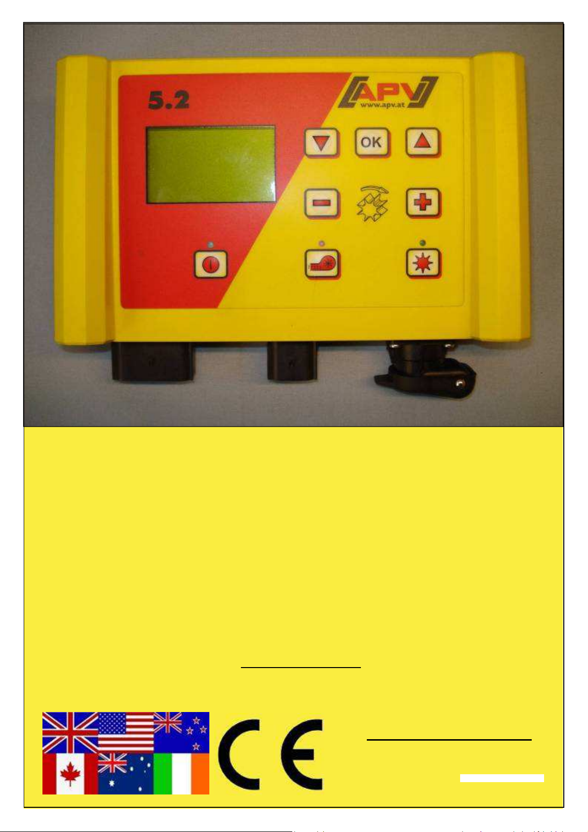
Original operating instructions
5.2
Read the "Quick start" menu item
carefully before operating!
From serial number
5.2-14xxx – 5.2-xxxxx
Version: 01/2017, V.2.7
Order No.: 00602-3-649
Page 2
2
Quality for Professionals
It should NOT be
an inconvenience or a luxury to read and comply with the
operating instructions; you cannot simply experience from
others that something is a good product, then make the
purchase and assume everything will be self explanatory.
Those who go down this route not only inflict damage on
their own property, but make the mistake of attributing the
cause of any failure to the machine, and not to themselves. In
order to be sure of success you must get into the spirit of the
thing, by learning about the purpose of each individual
device on the machine and by gaining experience in how to
use it. Only then will you be satisfied both with the machine
and with yourself. These operating instructions are intended
to help you achieve this.
Leipzig-Plagwitz 1872
Page 3

Quality for Professionals
Table of contents
1 Warranty ........................................................................................................................................................ 4
2 Quick start ...................................................................................................................................................... 4
2.1 Scope of delivery and fastening .............................................................................................................. 4
2.2 Electrical connection ............................................................................................................................... 5
2.3 Control module ....................................................................................................................................... 7
2.4 Initial starting up ..................................................................................................................................... 8
2.5 Main display .......................................................................................................................................... 11
2.6 Selection menu ..................................................................................................................................... 11
2.7 Quick start tutorial per video ................................................................................................................. 13
2.8 Initial operation of the controller without connected implement ............................................................ 13
3 Pro functions ................................................................................................................................................ 14
3.1 Calibration test (general) ...................................................................................................................... 14
3.1.1 Calibrating according to kg/ha ...................................................................................................... 14
3.1.2 Calibrating according to seeds/m² ................................................................................................ 17
3.1.3 Calibrating with the calibration button ........................................................................................... 20
3.2 Changing the application rate during operation .................................................................................... 20
3.3 Operation with speed sensor ................................................................................................................ 21
3.3.1 Pre-dosing .................................................................................................................................... 21
3.3.2 Calibrating the driving speed (tachometer) ................................................................................... 22
3.4 Operation with hoisting system sensor ................................................................................................. 24
3.5 Emptying ............................................................................................................................................... 25
3.5.1 Emptying with the calibration button ............................................................................................. 25
3.6 Operating hours counter ....................................................................................................................... 26
3.7 Surface area meter (seeded surface area) ........................................................................................... 26
3.8 Operating voltage / power display ........................................................................................................ 26
3.9 Languages ............................................................................................................................................ 27
3.10 Fan settings .......................................................................................................................................... 27
4 Control module 5.2 (language selection)...................................................................................................... 28
5 Controller messages .................................................................................................................................... 29
5.1 Notes .................................................................................................................................................... 29
5.2 Fault...................................................................................................................................................... 31
6 Problem solving ........................................................................................................................................... 34
7 Programming 5.2 (customer service) ........................................................................................................... 36
7.1 Fan ....................................................................................................................................................... 36
7.2 Signal for switching the sowing shaft on/off (warning tone) .................................................................. 37
7.3 Ground wheel ....................................................................................................................................... 37
7.4 Wheel sensor ........................................................................................................................................ 37
7.5 DIN 9684 signal (7-pin signal socket) ................................................................................................... 38
7.6 Radar sensor ........................................................................................................................................ 38
7.7 Tractor linkage / Hoisting system .......................................................................................................... 39
7.8 Hoisting system signal .......................................................................................................................... 39
7.9 Buzzer (warning signal) ........................................................................................................................ 39
7.10 Sowing shaft motor ............................................................................................................................... 40
7.11 Pressure sensor ................................................................................................................................... 40
7.12 Calibration button present ..................................................................................................................... 40
7.13 Measuring units .................................................................................................................................... 41
7.14 Implement type ..................................................................................................................................... 41
7.15 Restore factory settings ........................................................................................................................ 41
8 Accessories .................................................................................................................................................. 42
8.1 7-pin signal cable (item no.: 00410-2-006) ........................................................................................... 42
8.2 Sensor GPSa (item no.: 00410-2-107) ................................................................................................. 43
8.3 Radar sensor MX35 (item no.: 00410-2-084) ...................................................................................... 44
8.4 Wheel sensor (item no.: 00410-2-007) ................................................................................................. 45
8.5 Tractor linkage lower bar sensor (item no.: 00410-2-008) .................................................................... 46
8.6 Tractor linkage upper bar sensor (item no.: 00410-2-074) .................................................................... 47
8.7 Tractor linkage pull switch sensor (item no.: 00410-2-115) .................................................................. 48
8.8 Splittercable (item no.: 00410-2-010) ................................................................................................... 49
8.9 Set of adapter cables for tractors (item no.: 00410-2-022) ................................................................... 50
8.10 Calibration button (item no.: 00410-2-094) ........................................................................................... 51
9 Connection diagrams ................................................................................................................................... 52
9.1 PS connection diagram......................................................................................................................... 52
9.2 MD connection diagram ........................................................................................................................ 54
3
Page 4
4
Fig.: 1
Quality for Professionals
1 Warranty
Please check machine immediately upon receiving for any damage from transport. We
cannot acknowledge any claims grounded with damage from transport later on. Oneyear warranty from date of delivery (your bill or delivery note counts as a certificate of
warranty) are warranted.
The warranty is granted in case of material or constructional errors and does not include
parts that are damaged by normal or excessive use.
The warranty expires:
• when damages occur through external forces (e.g. opening the control).
• when faulty operation is at hand.
• if the control module is open.
• when the stipulated requirements are not met.
• when the machine is altered, augmented or equipped with other parts without our
consent.
2 Quick start
2.1 Scope of delivery and fastening
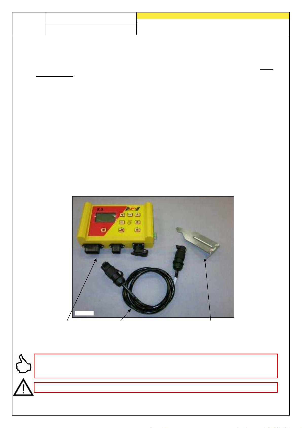
Control module Power cable Module mount
Fasten the mount (provided as part of the standard delivery) into the cab with two
screws.
TIP: Pay attention to the angle at which you are viewing the module to ensure optimum
readability of the display. You may have to bend the mount slightly to set the correct
angle.
ATTENTION: If possible, do not roll the cable into a coil!
Page 5
5
Fig
.: 2
Quality for Professionals
2.2 Electrical connection
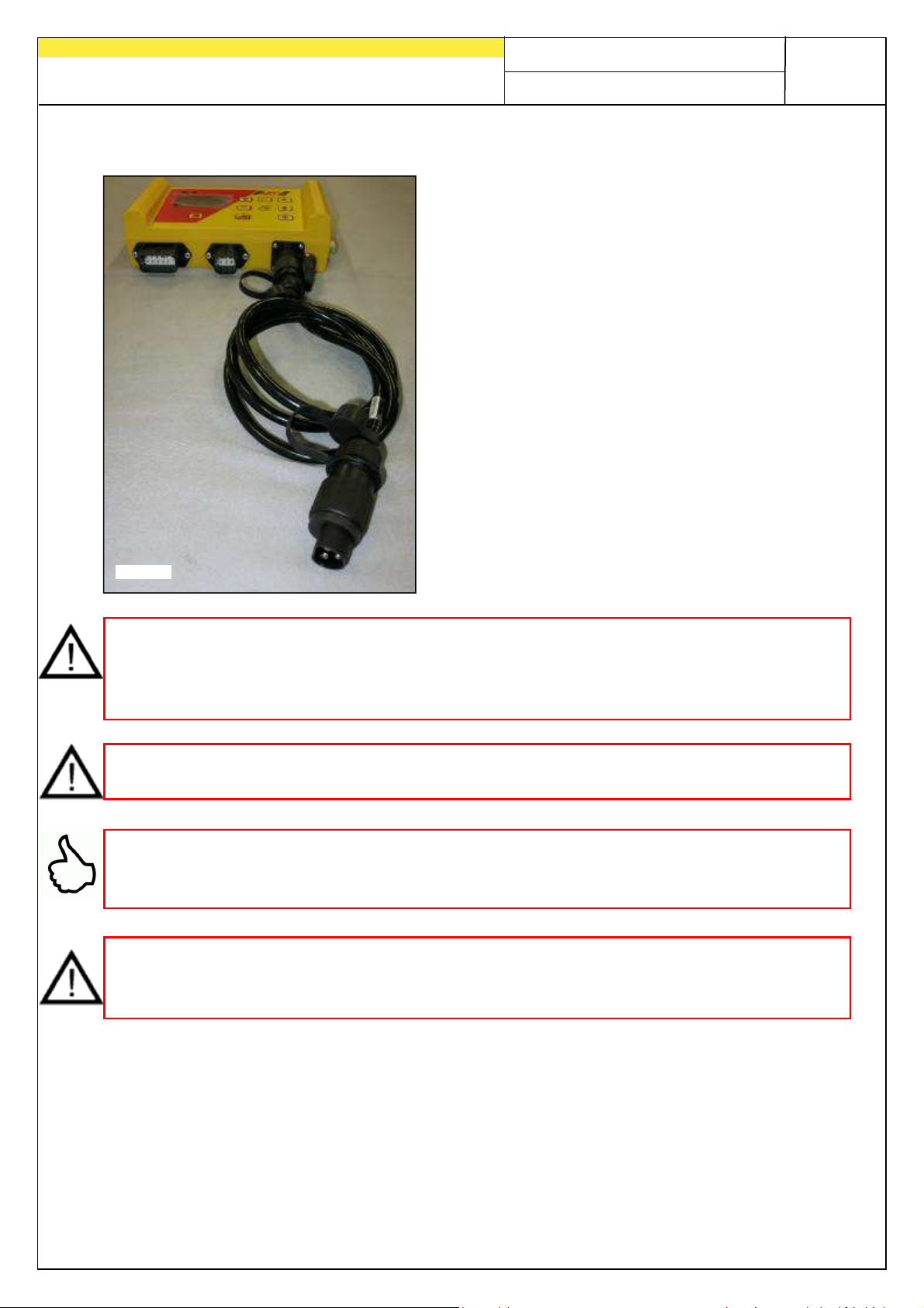
You can connect the cable, provided as part of
the standard delivery, directly to the 3-pin
standard socket in the tractor cab. Connect the
other end to the control module.
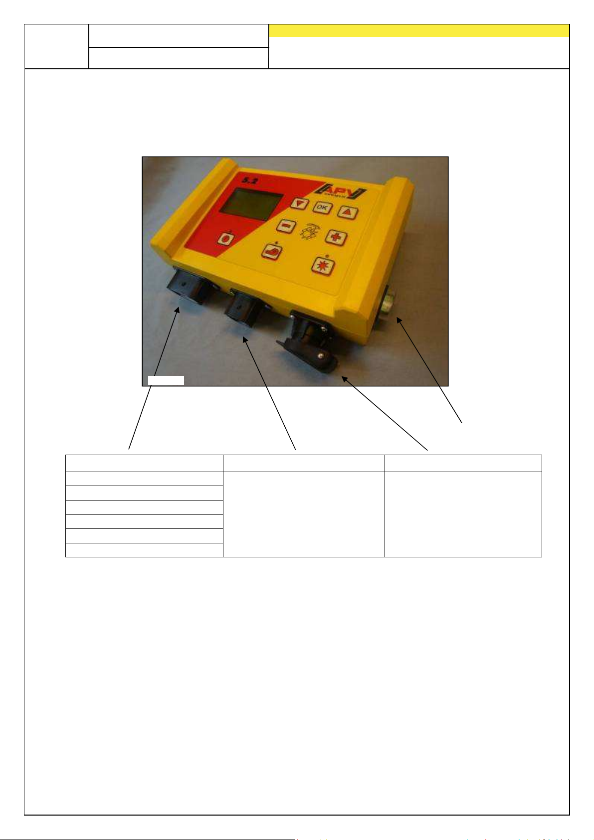
The (30 A) fuse is on the right side of the control
module.
Store excess cable in the driver's cab to avoid
trapping it.
IMPORTANT NOTES:
The 12 Volt power supply must NOT be connected to the cigarette lighter!
After using the device, the controller should be disconnected (for safety reasons).
ATTENTION: Failure to observe these instructions can result in damage to the control
module!
TIP: If your tractor does not have a standard socket, it can be retrofitted with the
Complete Cable Kit for Power Sockets, Tractor Retrofit 8 m long (Item no. 00410-2-022)
or motor vehicle retrofit 3 m long (Item no. 00410-2-027) (special accessory).
ATTENTION: If the battery is charged by a charger which is in the "Start" operating
mode, this may result in voltage peaks! These can damage the control module's
electrical system if the control module is also connected when charging the battery!
Page 6
6
Fig.: 3
Quality for Professionals
30 A fuse
12-pin connector 6-pin connector 3-pin connector
Ground wheel
7-pin Signal cable
Hoisting system sensor
Wheel sensor
Radar sensor
Sensor GPSa
More specific details of the different sensor types are provided under Accessories.
Connection to the sowing
implement (equipment
cable)
Connection to the battery
(power cable)
These are available to the customer as accessories upon request!
Page 7
2.3 Control module
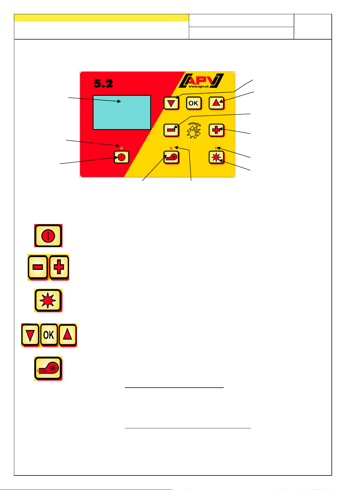
On/Off button
Fig.: 4
Graphic display
Lights up when
the controller is
switched on
Quality for Professionals
Cursor "down"
Cursor "up"
Reduce sowing shaft
speed
Increase sowing shaft
speed
Lights up when the
sowing shaft turns
Sowing shaft on/off
Fan/ Spreading plate
on/off
lights up when the
fan/spreading plate
is switched on
The "On/Off” button, which is used to switch the device on and off, is
located at the bottom left.
With these buttons you can change the speed of the sowing shaft and
change the respective parameters in the menu items.
Below this is the button for the sowing shaft, "on" and "off". The sowing
shaft starts to turn when the "on/off" button is pushed. The indicator light
starts to light up at the same time.
Control module for navigating through the menu items
Switches the fan or the spreading plate (for Type MDS) on or off.
• for electric fans/spreading plate:
The indicator light lights up when the fan/spreading plate
starts. The indicator light lights up if the fan runs
continuously.
• for hydraulic fans (with pressure sensor):
The indicator light lights up as soon as the fan has built up
pressure.
7
Page 8
8
Quality for Professionals
2.4 Initial starting up
When starting up for the first time or if the programming menu is reset to factory
settings, the following settings must be undertaken on your 5.2 control box:
TIP: Depending on the selected settings, not all of the points will be requested.
However, you can also change the points as described under Point 7.
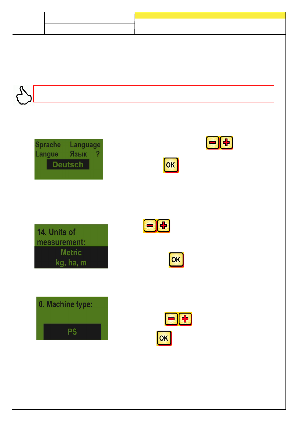
Languages
Select your desired menu language here.
Select the desired language with the button
and confirm with the button!
Measuring units
Select metric units (m, ha, km/h, kg) or imperial units (ft, ac, mph, lb) here.
Using the buttons, select
metric (kg, ha, m) or imperial (lb, ft, ac)
and confirm with the button.
Implement type
Here, you must select your implement type (PS, MDP,
MDG, MDS).
Use the buttons to make your selection and
confirm with the button.
Page 9
Quality for Professionals
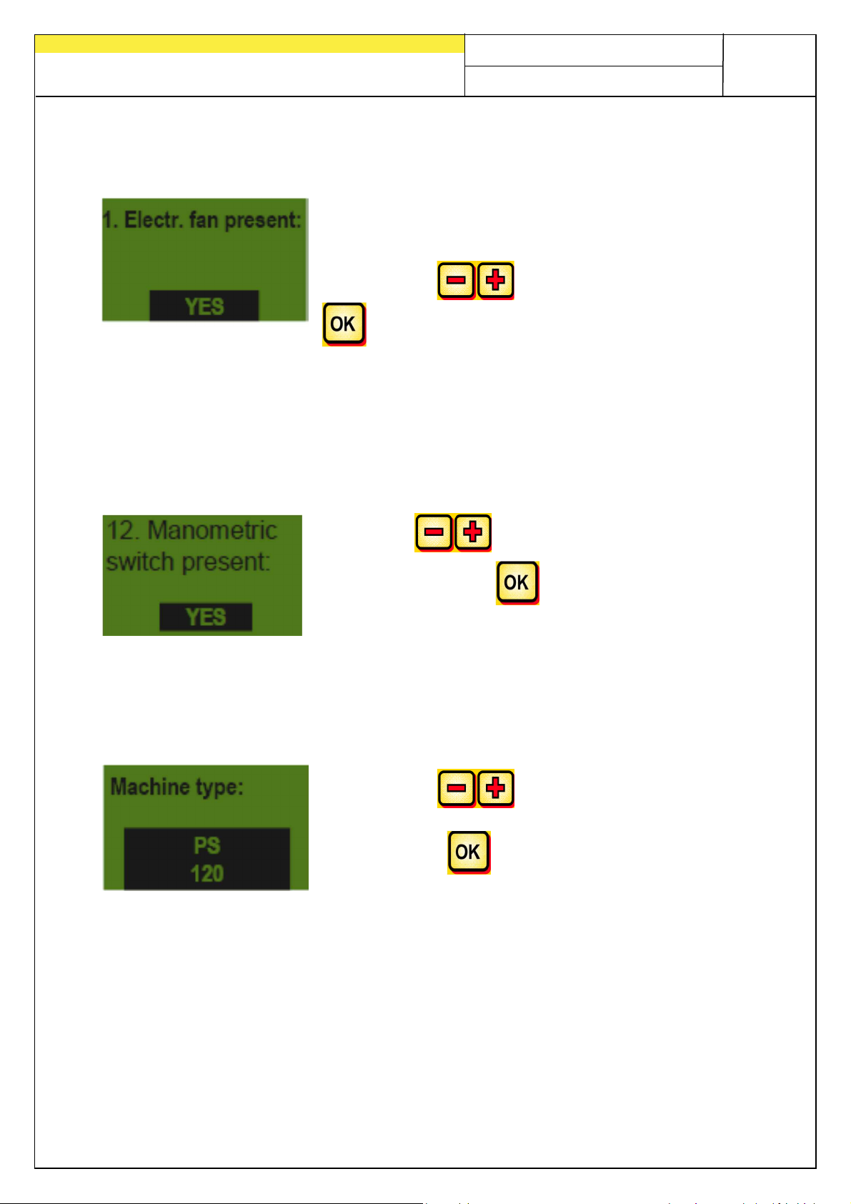
Fan
Select whether you have an electric or hydraulic fan installed on your PS here.
YES – electrical fan installed
NO – hydraulic (or external) fan installed
Select with the button and confirm with the
button.
Pressure sensor
Here, you must set whether your PS has a pressure sensor (measures the air flow
from the hydraulic blower fan). It is installed as a standard on all PS with hydraulic
blower fan as of 2017.
Using the buttons, select YES or NO
9
and confirm with the button.
Machine type
Enter the PS type (PS 120, PS 200, PS 300, PS 500, PS 800, PS 1200, PS 1600) for
your device here.
Select with the button and
confirm with the button.
Page 10
10
Fig.: 5
Quality for Professionals
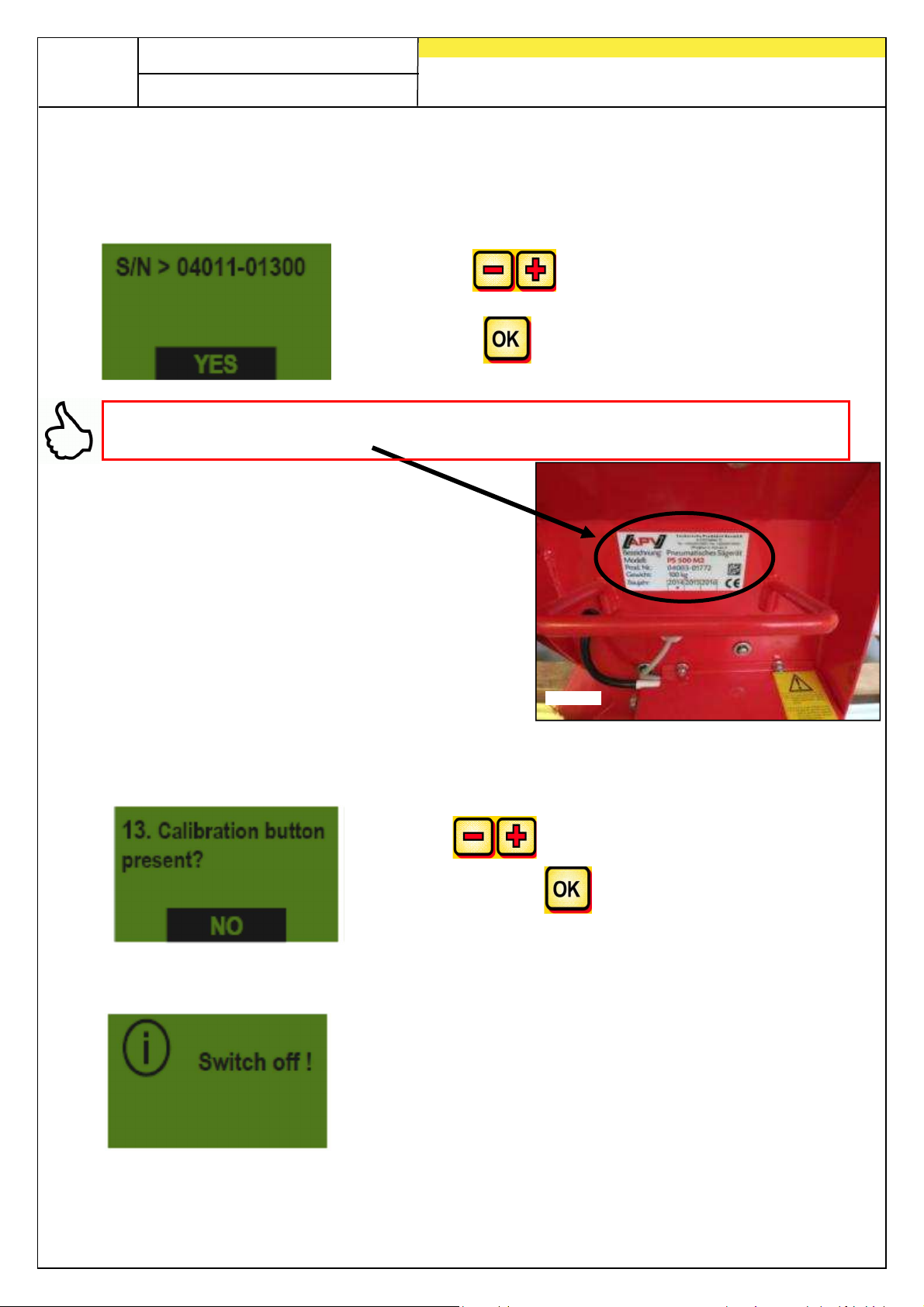
Serial number (with PS 800)
Here, select whether your PS 800 has a serial number higher than 01300. This will store
the right motor characteristic in the control module.
Select with the button and
confirm with the button.
TIP: You can find the serial number for your implement on the same side as the wiring
on your PS (see Fig.: 5).
Calibration button present
Here you specify whether a calibration button (available as an accessory) is installed
on your implement.
Using the buttons, select YES or NO
and confirm with the button.
After entering this data, the control box switches off automatically so that the entries can
be saved.
Page 11
2.5 Main display
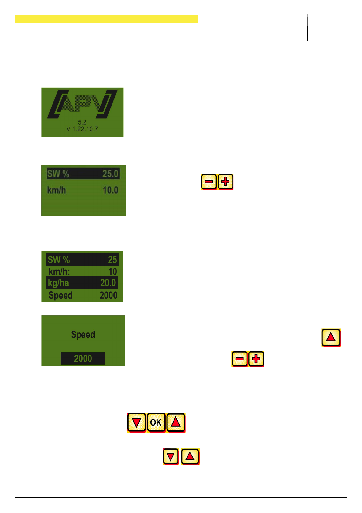
Switch-on message
Is shown during the switch-on procedure and shows the type
and device version!
This information is very helpful in the case of service and is
even essential for malfunctions to be able to perform
diagnosis!
PS, MDP or MDG operating mode
SW %: set speed for the seeding shaft (in %)
Must be set using the buttons on the control
module or automatically when performing the calibration test.
km/h: forward speed [km/h] defined in the
"Calibration test" menu item.
MDS operating mode
SW %: set speed for the seeding shaft (in %)
km/h: forward speed [km/h] defined in menu item
I "Calibration test".
kg/ha: current spread rate (is only displayed if a
valid calibration was performed
Speed: currently set spreading plate speed is displayed on
the second menu page, can be reached by pressing the
11
Quality for Professionals
button and changed with the buttons.
2.6 Selection menu
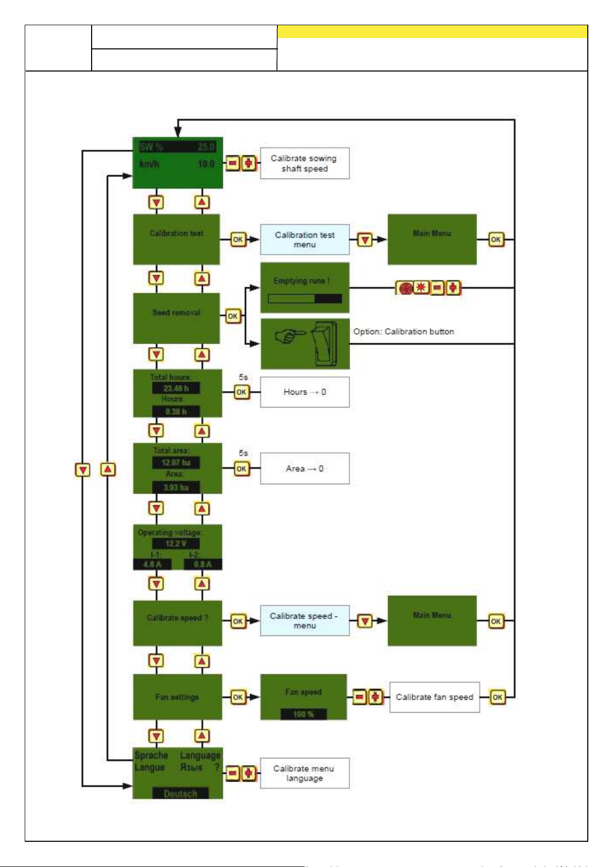
After the device has been switched on, you can navigate through the menu using the
following three buttons:
The cursor buttons are used in the menu to move one menu item up
or down.
Page 12
12
Quality for Professionals
The following menu items are available:
Page 13
Quality for Professionals
2.7 Quick start tutorial per video
Via the link below you are taken to the different videos:
www.apv.at Service Videos User Guide
The following tutorial videos can be viewed there:
• Calibration test in kg/ha with the 5.2 control module
• Calibration test according to grain/m² with the 5.2 control module
• Calibrate speed with the 5.2 control module (100 m, manual, calibration
value)
• PS 120-500 adaptation to the 5.2 control module for hydraulic fan
• PS 800 adaptation to the 5.2 control module for hydraulic fan
13
2.8 Initial operation of the controller without connected implement
The control module can also be operated for the first time without connected
implement. However, the following error message then appears: "Motor not
connected (...)".
These error messages can be acknowledged by for 15 sec., then they
reappear. This mainly serves for reading out the operating hours, hectare counter
and various settings without having to connect the control module to the implement.
Page 14
14
Quality for Professionals
3 Pro functions
3.1 Calibration test (general)
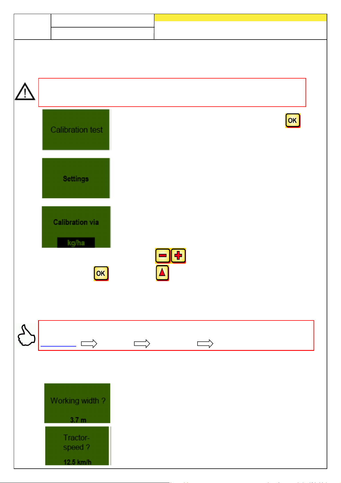
NOTE: In addition to execution of a calibration test (setting the speed of the sowing
shaft) this menu item is also used for setting the working width and the driving speed.
The entered values are also used for the surface calculation (seeded area).
Go to the calibration test menu item and press the
button.
The following parameters may be set via this menu item:
Here you can select whether to calibrate according to kg/ha
or seeds/m² (with thousand grain weight and germination
capacity).
You can change the settings with the buttons.
By pressing the button or the button, the view jumps to the next menu
point.
3.1.1 Calibrating according to kg/ha
Here you will find the tutorial “Calibrating according to kg/ha” per video:
www.apv.at Service Videos User Guide
If you have selected “Calibrating by kg/ha” in the settings menu, the following points
will appear in the calibration menu:
The working width must be input here.
(Note overlapping!)
Input the driving speed here.
Page 15
15
Quality for Professionals
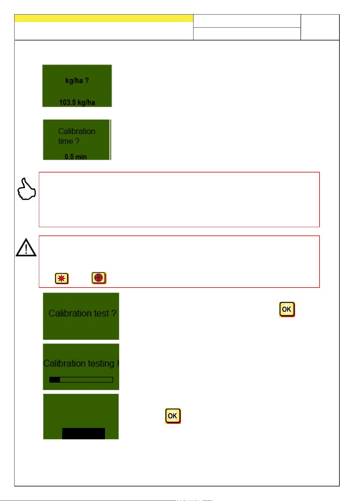
Input the desired output volume here.
(e.g. 103.5 kg/ha)
Set the duration for the seed rate calibration test here.
If a calibration button is installed and "Calibration button
present?" has been set to YES in the programming menu, this
item will not appear.
TIP:
• For smaller seeds, such as rape, phacelia, poppy, etc., it is best to calibrate
for 2 minutes.
• The standard calibrating time is 1 minute
• For larger seeds, such as wheat, barley, peas, etc., it is best to calibrate for
0.5 minutes.
NOTE: Before starting the test, make sure that you have also removed the calibration
cover and determine whether you will use this or the calibration slide. Ensure that you
have installed the calibration sack or a collection container so that they are precisely
positioned! The seed rate calibration test can be cancelled at any time by pressing
the or the button on the control module.
If all values are correctly set, commence the test .
Seed rate calibration test runs:
After starting, the sowing wheel starts to turn automatically
without fan motor. The sowing shaft stops automatically once
the set time has elapsed.
If a calibration switch is present, the system waits until it is
activated (see 3.1.3).
Input
Calibr. Value:
3.25 kg
Now weigh the calibrated seed quantity and enter the weight,
confirm with .
Page 16
16
Quality for Professionals
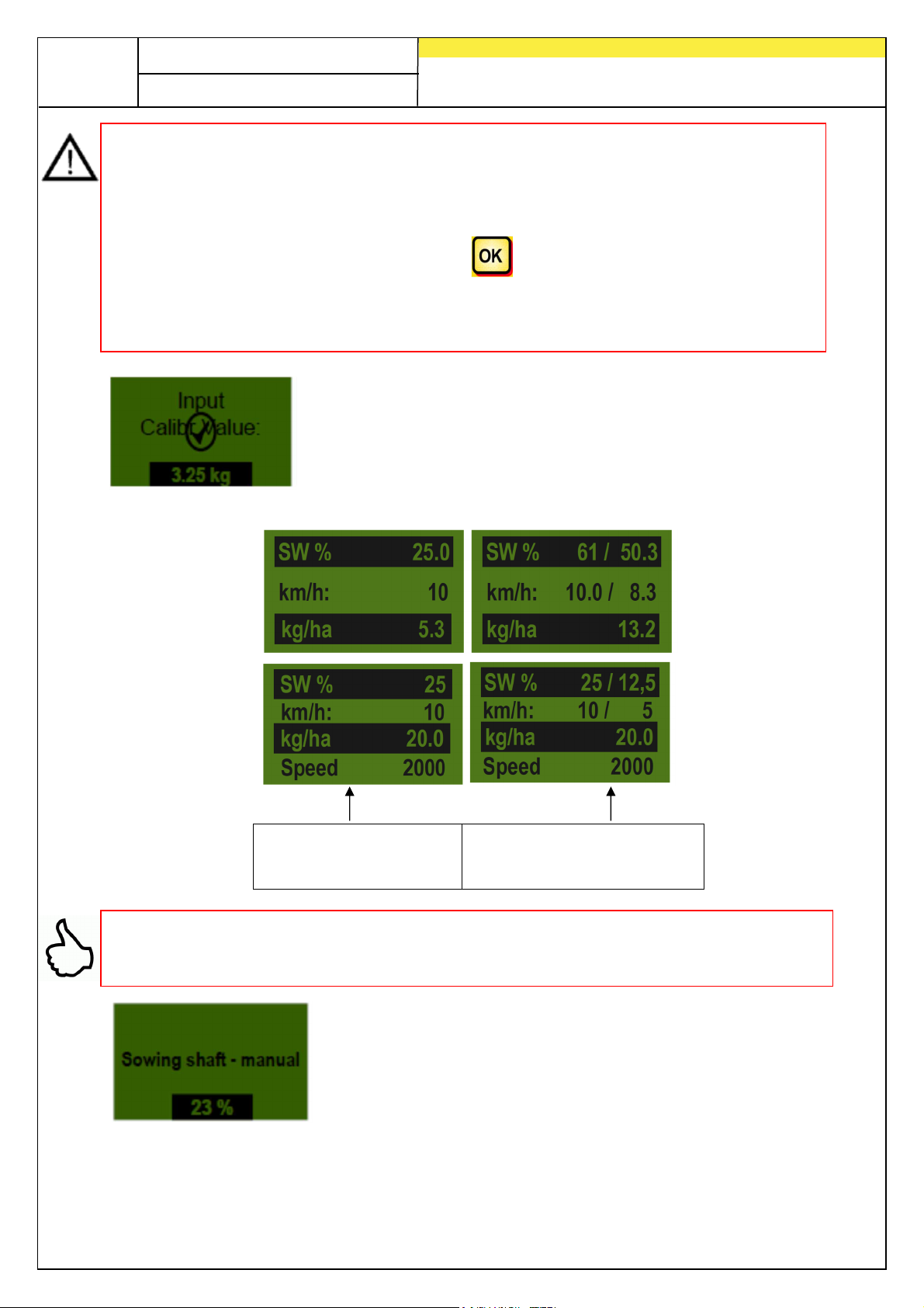
NOTE: the weight of the collection bucket or calibration sack must be deducted.
To really spread the desired spread rate, we recommend repeating the calibration
test until the message "Test not precise! Repeat?“ no longer appears. If "Seeding
shaft speed too high" appears on the display, the seeding shaft is not able to rotate
fast enough. If "Seeding shaft speed too low" appears, the seeding shaft is not able
to rotate slowly enough (see 5.1). With the button, you can return to the
previously displayed value. Only when the automatic readjustment of the seeding
shaft is under 3 % (difference), the "checkmark symbol" and the spread quantity in
kg/ha will appear on the main screen.
The sowing shaft speed now automatically calculates
correctly. The display then returns to the main menu.
PS, MDP, MDG:
MDS:
The set kg/ha values
are now displayed.
The two-column display
appears if you are working
with a speed sensor.
TIP: The test will continue if your PS is equipped with a level sensor and if the
"Container almost empty" message appears on the display. However, insufficient
seed in the container can distort the precision of the seed rate calibration test.
This menu item is used to approximately preset the speed
of the sowing shaft. The speed (%) of the sowing shaft
does not need to be changed, because the settings from
the calibration test are automatically applied.
Page 17
17
Quality for Professionals
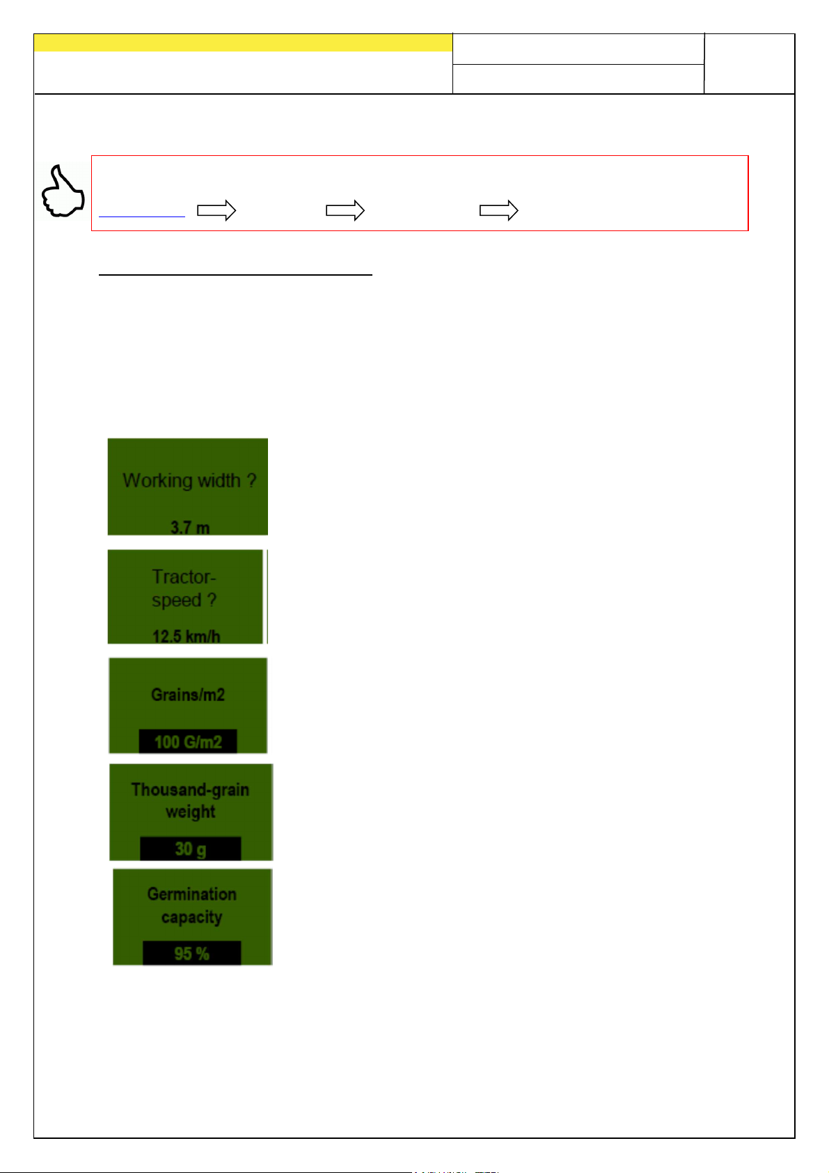
3.1.2 Calibrating according to seeds/m²
Here you will find the tutorial “Calibrating according to seeds/m²”:
www.apv.at Service Videos User Guide
Calculation of the application rate:
TSW (g) x grains/m² x 100
Quantity of seed (kg/ha) = ------------------------------------------------
Germination capacity (%)
If you have selected “Calibrating by seeds/m²” in the Settings menu, the following
items will appear in the calibration menu:
Input the working width here.
(Note overlapping!)
Input the driving speed here.
Input the desired seeds/m² here.
The respective thousand grain weight must be input here.
The germination capacity of the seed is set here.
Page 18
18
Quality for Professionals
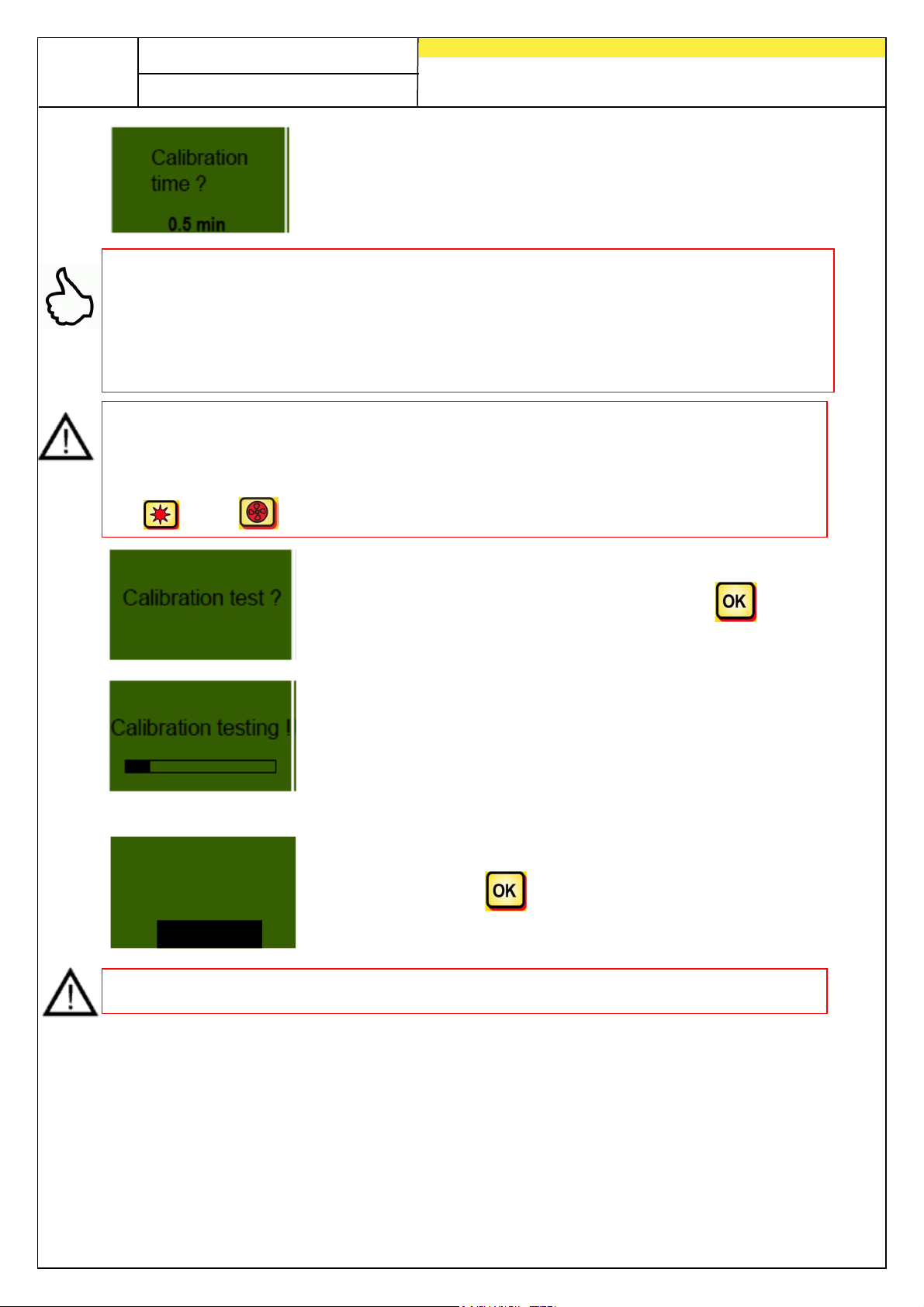
Set the duration for the seed rate calibration test here.If a
calibration button is installed and "Calibration button
present?" has been set to YES in the programming menu,
this item will not appear.
TIP:
• For smaller seeds, such as rape, phacelia, poppy, etc., it is best to
calibrate for 2 minutes.
• The standard calibrating time is 1 minute
• For larger seeds, such as wheat, barley, peas, etc., it is best to calibrate for
0.5 minutes.
NOTE: Before starting the test, make sure that you have also removed the calibration
cover and determine whether you will use this or the calibration slide. Ensure that you
have installed the calibration sack or a collection container so that they are precisely
positioned! The seed rate calibration test can be cancelled at any time by pressing
the or the button on the control module.
If all values are correctly set, commence the test .
Seed rate calibration test runs:
After starting, the sowing wheel starts to turn automatically
without fan motor. The sowing shaft stops automatically once
the set time has elapsed.
If a calibration button is present, the system waits until it is
activated (see 3.1.3).
Input
Calibr. Value:
3.25 kg
NOTE: Deduct the weight of the collection bucket or calibration sack.
Wiegen Sie nun die abgedrehte Saatgutmenge ab und geben
das Gewicht ein, mit bestätigen.
To be able to spread the desired output volume, we recommend repeating the seed
rate calibration test until the "Test not precise! Repeat?" message no longer appears.
If "Drill shaft RPM too high" appears on the display, the sowing shaft cannot turn fast
enough. If "Drill shaft RPM too low" appears on the display, the sowing shaft cannot
turn slowly enough (see also 5.1).
Page 19
19
Quality for Professionals
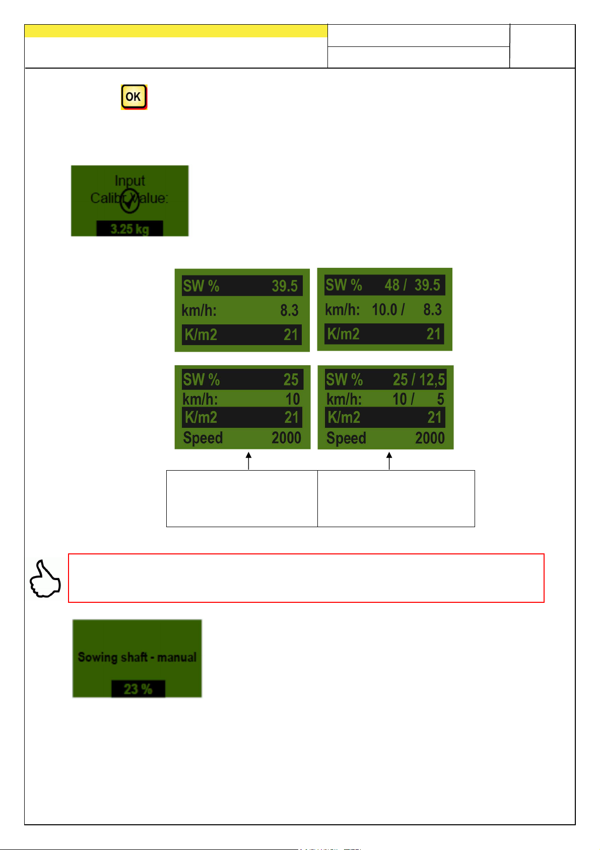
With the button, the user is returned to the previously displayed value. The "tick
symbol" and the output volume in kg/ha only appear on the main display if the
automatic re-adjustment of the sowing shaft is below 3 % (difference).
The sowing shaft speed now automatically calculates
correctly. The display then returns to the main menu.
PS, MDP, MDG:
MDS:
The set grains/m²
values are now
displayed.
The two-column display
appears if you are
working with a speed
sensor.
TIP: The test will continue if your machine is equipped with a level sensor and if the
"Container almost empty" message appears on the display. However, insufficient
seed in the container can distort the precision of the seed rate calibration test.
This menu item is used to approximately preset the speed
of the sowing shaft. The speed (%) of the sowing shaft
does not need to be changed, because the settings from
the calibration test are automatically applied.
3.1.3
Page 20
20
Quality for Professionals
3.1.3 Calibrating with the calibration button
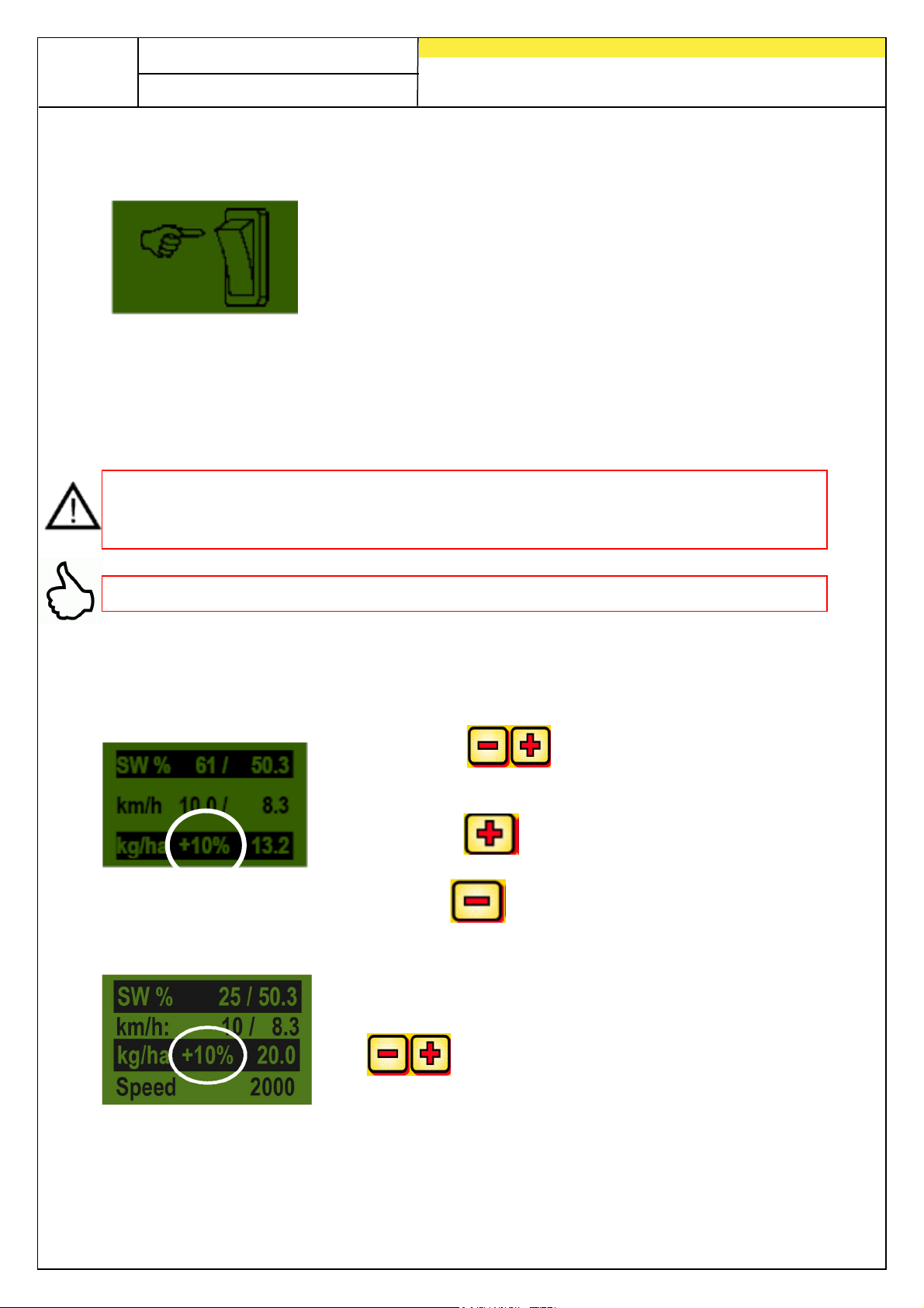
If you have installed a calibration button on your machine,
and if it is set to YES in the programming menu (see also
7.12), then the “Calibration time” menu item will not be
displayed. Make the settings as desired. Then press “Start
test”. Then the following screen will be shown in the display
and the system will wait until the calibration button is
activated. The sowing shaft continues to rotate until the calibration button is
deactivated. The control module calculates the target rate from the calibration time
and shows this in the display. Now weigh the calibrated amount and enter this
amount in the control module. If required, repeat the procedure to get a more precise
setting.
Note: In order to achieve corresponding exactness, the calibration button must be
held down for at least 20 seconds, otherwise the message "Calibration time too
short!" will appear and the kg/ha or grains/m² will not be shown in the main display.
TIP: The container may also be emptied if the calibration button is activated.
3.2 Changing the application rate during operation
PS, MDP, MDG:
By pressing the sowing shaft buttons - as soon
as a successful calibration test has been executed - the
application rate will be increased or decreased by 5%.
Each time the is pressed the application rate is
increased by 5% of the entered application rate, and by
pressing the application rate is reduced in 5%
increments.
MDS:
The application rate can be increased or decreased by a
max. of 50%!
If a (successful) calibration test is not present, by pressing
the buttons, the sowing shaft speed will be
increased or decreased in 1% increments.
Page 21

Quality for Professionals
TARGET
ACTUAL
TARGET value
ACTUAL value
SW % (sowing shaft)
km/h (driving speed)
TARGET
ACTUAL
3.3 Operation with speed sensor
If you are working with a speed sensor, then your display will look like this:
PS, MDP, MDG: MDS:
21
value
value
value
value
Set sowing shaft speed (in
%). Set using the
Actual sowing shaft speed
(in %). This is calculated
and displayed by control
buttons on the
control module or for
module depending on
driving speed.
executing a calibration
test.
This is set in the menu item
“Calibration test”.
Actual driving speed in
km/h. This is measured by
the sensor and displayed
on the control module.
3.3.1 Pre-dosing
If the button is depressed for 1 second, the sowing shaft starts to turn at the
speed set for the calibration test for as long as the button remains depressed.
This feature enables you to avoid unseeded areas (at the beginning of the field or
when the tractor is at a standstill on the field). When the button is released the control
module works again with the signals from the respective speed sensor. If you are
working with a lifting unit sensor, then the soil processing unit must be in the "work"
position.
Page 22
22
Quality for Professionals
3.3.2 Calibrating the driving speed (tachometer)
Calibration must be carried out because the control module uses this value as a
basis for all calculations (speed display, dosing, surface area calculation).
There are 3 calibration options.
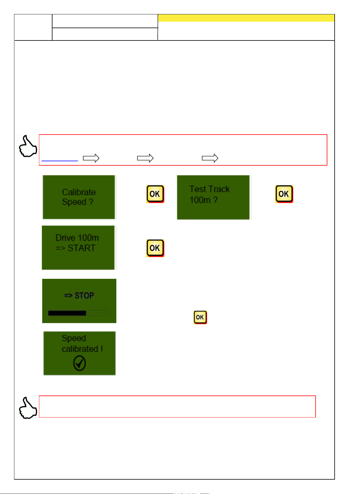
3.3.2.1 Test distance 100 m
You will find the video tutorial “100 m test distance” here:
www.apv.at Service Videos User Guide
>> >>
>>
Drive precisely 100 m. During travel, the module counts the
impulses of the path covered on the display.
After 100 m, press the stop button
This is displayed when calibration is completed.
TIP: The max. values for the wheel sensor are 1500 pulses per 100 m, all other
sensors have a maximum of 51200 pulses per 100 m.
Page 23
Quality for Professionals
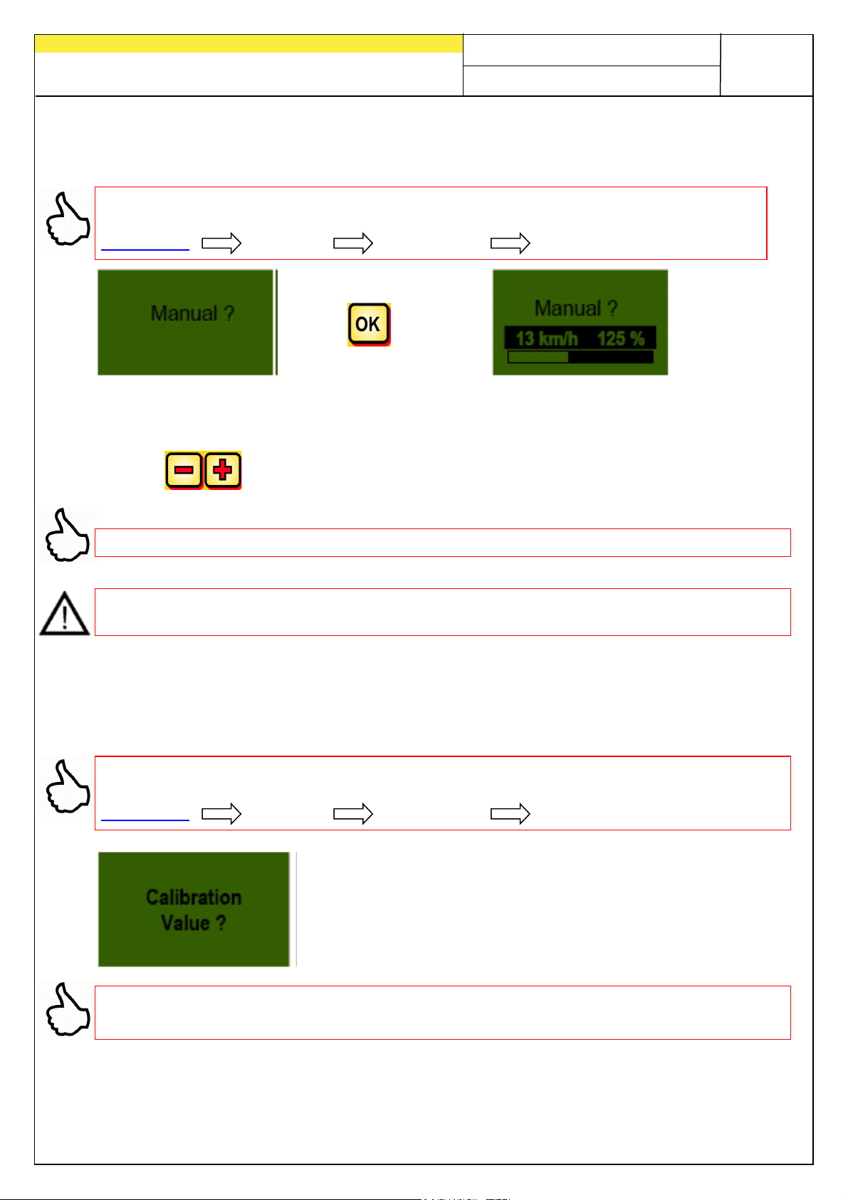
3.3.2.2 Manual calibration
You will find the video tutorial, “Manual calibration”, here:
www.apv.at Service Videos User Guide
> >
While driving, compare the speed on the display with the speed on the tractor's
display
23
Use the buttons, to correct the values until the values are the same.
TIP: The calibration may be completed here manually without driving 100 m.
NOTE: The calibration is only truly accurate when a radar or GPS sensor is installed
on your tractor. Otherwise, the slippage is not included in the forward speed!
3.3.2.3 Calibration value
You will find the video tutorial “Adapting the calibration value” here:
www.apv.at Service Videos User Guide
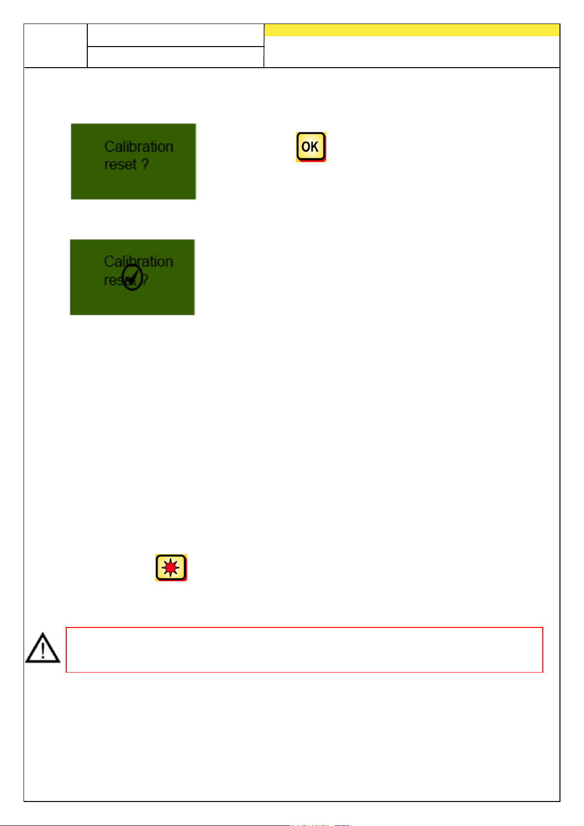
The impulses/100 m may be manually set here.
TIP: Once the device has been calibrated, note the value and readjust the setting
here as necessary.
Page 24
24
Quality for Professionals
3.3.2.4 Resetting the calibration
Confirm with the button.
Resets the value to the factory setting.
This is displayed after the resetting of the calibration.
3.4 Operation with hoisting system sensor
The sowing shaft of the PS can automatically turn on and stop via a hoisting system
sensor when lifting and lowering the implement. This enables you save the effort of
manually switching the sowing shaft on/off on headlands.
There are 3 types of hoisting system sensors:
• 7-pin Signal cable (see point 8.1)
• Tractor linkage lower bar sensor (see point 8.5)
• Tractor linkage lower upper bar sensor (see point 8.6)
• Tractor linkage pull switch sensor (see point 8.7)
By pressing the button for 2 seconds, the sowing shaft may be switched on
independently of the position of the lifting unit sensor. However, this only functions
when you are working without a speed sensor.
NOTE: The acoustic signal that sounds when switching the sowing shaft on / off can
be deactivated as described in point 7.2.
Page 25
25
Quality for Professionals
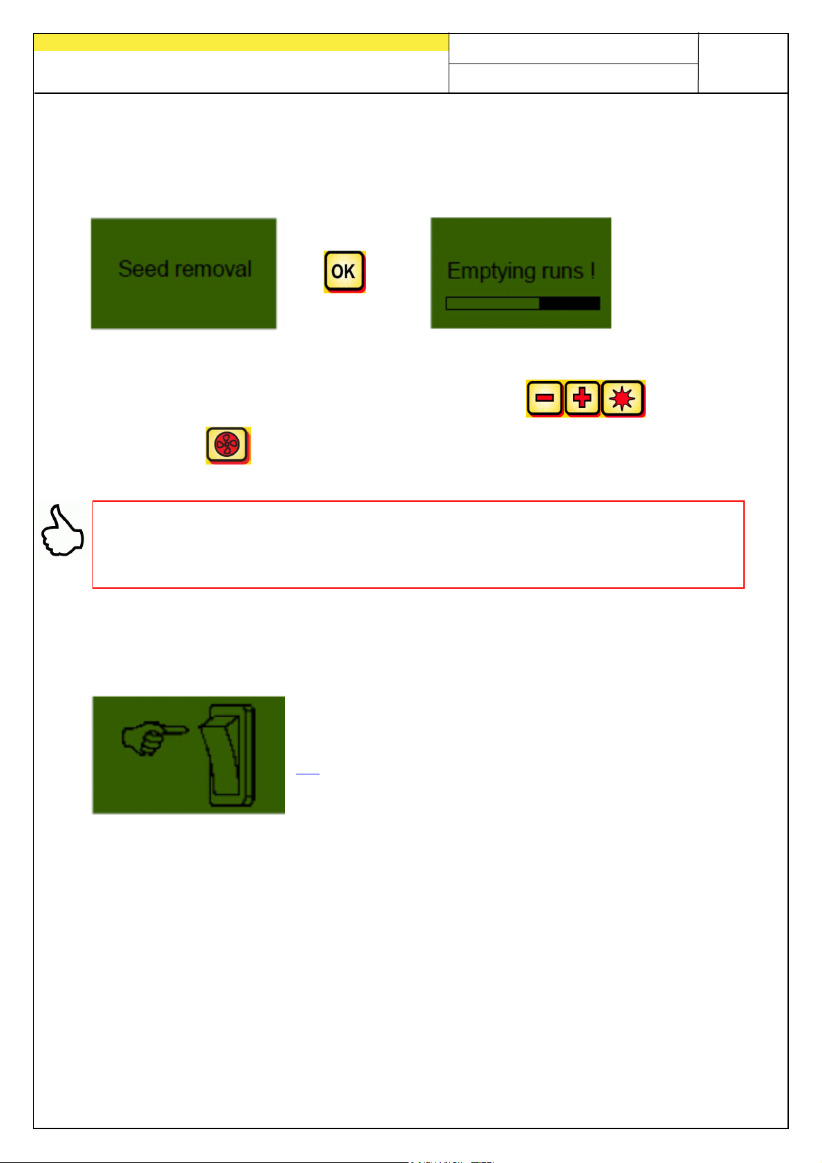
3.5 Emptying
This menu item is used for practical emptying of the container. (e.g. when work has
ended, when changing seed, when replacing the sowing shaft).
> >
The motor turns at its highest speed (without fan).
Emptying may be stopped at any time by activating the
buttons or the button. Then the display will again be shown in the main menu.
TIP: Before starting emptying, make sure that you have also removed the calibration
cover and determine whether you will use this or the calibration slide. Ensure that
you have installed the calibration sack or a collection container so that they are
precisely positioned!
3.5.1 Emptying with the calibration button
If you have installed a calibration button on your machine
and if it is set to YES in the programming menu (point
7.2), then the container may also be emptied. The sowing
shaft rotates for as long as the calibration button is
pressed.
Page 26
26
Quality for Professionals
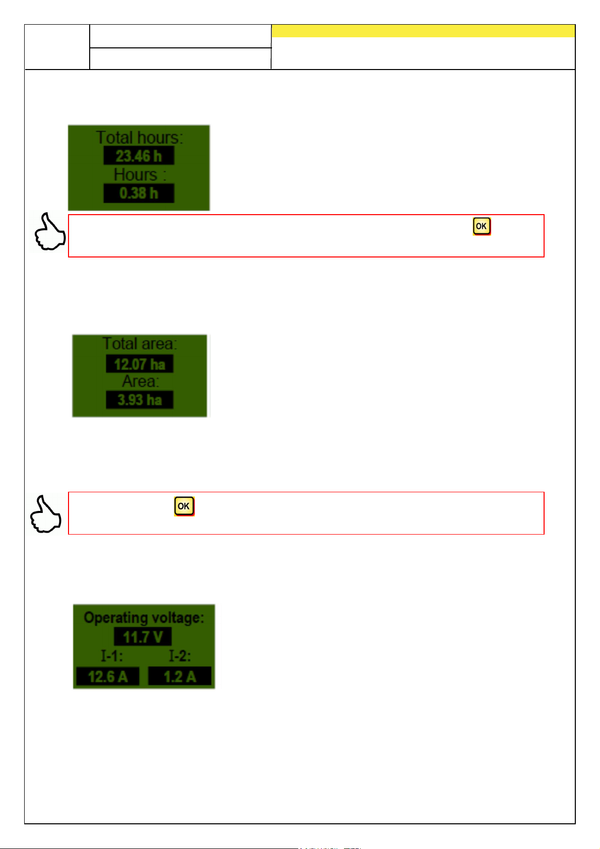
3.6 Operating hours counter
Operating hours counter = running time of sowing shaft.
Shows the total hours and the hours per day.
TIP: The hours per day may be reset to zero by pressing and holding the button
for 5 seconds. Total hours cannot be set to zero.
3.7 Surface area meter (seeded surface area)
The values Indicates the complete seeded surface area
in hectares.
The values are set automatically when the calibration test is executed. See menu
item 2.6.
Counts only the surface where seed was applied.
TIP: Pressing the button (keep it depressed for 5 seconds) resets the area to
zero. The entire surface area cannot be set to zero.
3.8 Operating voltage / power display
Displays the current operating voltage.
If this value begins to fluctuate significantly during
operation, there are problems with the on-board
electronics. This can lead to a poor spreading result!
I-1
: Displays the fan motor's power consumption in amperes.
I-2
: Displays the electric sowing motor's power consumption in amperes.
Page 27
27
Quality for Professionals
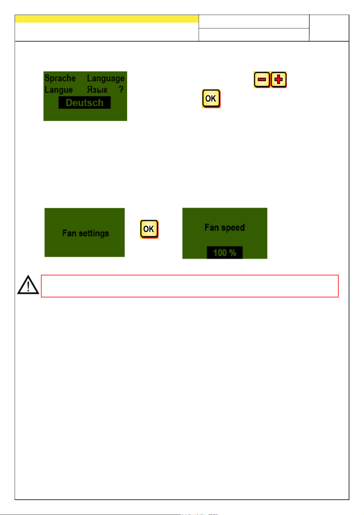
3.9 Languages
Select the desired language with the button
and confirm with the button!
3.10 Fan settings
This menu item is used to set the fan speed and the fan capacity. This can be helpful
if fine (light) seeds (e.g.: micro-granulate, rape, etc.) are being processed or if air
separators are equipped. In addition, the fan's power consumption may be reduced if
the entire fan capacity is not needed for the work.
>
A A >
NOTE: This screen appears only if you are in the PS or MDP operating mode and you
are using an electric blower.
Page 28
28
Quality for Professionals
4 Control module 5.2 (language selection)
Starting at software version V1.25, the following languages can be
selected:
• German (Deutsch)
• English
•
French (Français)
• Dutch (Nederlands)
• Danish (Dansk)
• Polish (Polski)
• Italian (Italiano)
• Spanish (Español)
•
Czech (Česky)
• Hungarian (Magyar)
• Finnish (Suomi)
• Portuguese (Português)
• Romanian (Romana)
• Swedish (Svenska)
• Estonian (Eesti)
• Latvian (Latvijas)
• Lithuanian (Lietuvos)
• Norwegian (Norske)
• Slovenian (Slovenski)
• Russian (Pycckий)
• Serbisch (Srpski)
• Turkish (Türkçe)
Pressing the button returns to the main display.
Page 29
5 Controller messages
•
•
•
•
•
5.1 Notes
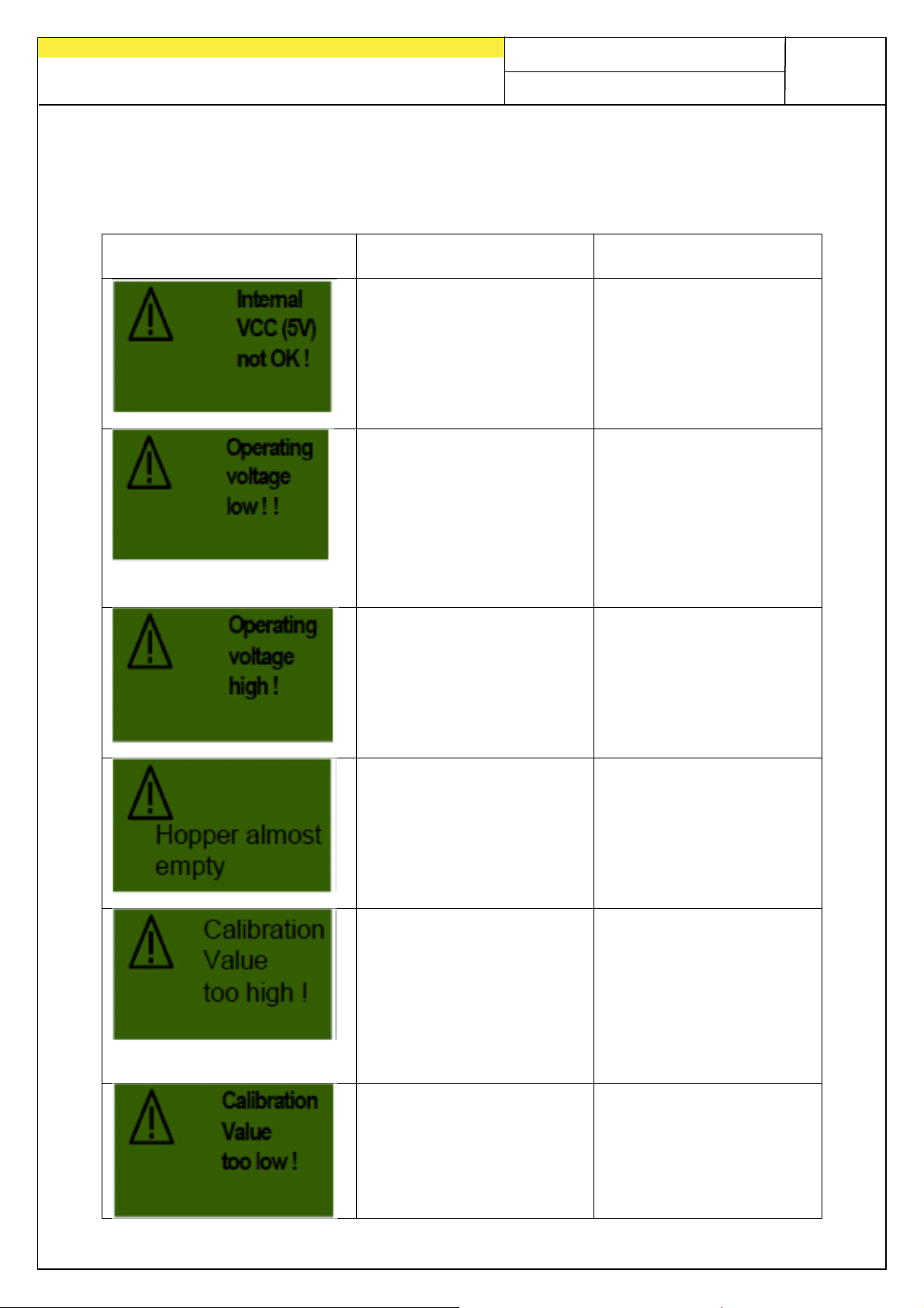
Display Cause Solution
29
Quality for Professionals
Displayed if the internal
control voltage is below
a minimum value.
Displayed if the
operating voltage is too
low.
Indicates that the
operating voltage is too
high.
This message is
displayed if the level
sensor has not been
covered by seed for
more than 30 seconds.
Displayed if the pulse
count is too high when
calibrating.
Appears when no sensor
is detected during
calibration, or when the
number of pulses is too
low (wheel sensor < 10,
Radar/GPSa sensor
Return to factory
Minimise consumers
• Check battery
• Check cabling
• Check generator
• Operating voltage
must be above 10 V
(Point 3.8)
Check generator
Refill seed
• Adjust sensor (turn
further down)
• Adjust the sensitivity
of the fill level sensor
Wheel sensor:
• Reduce the number of
magnets for the wheel
sensor
• Install the sensor on
the shaft rotating more
slowly
Check the sensor
• Check the cabling
• Check the settings for
the speed sensor
Wheel sensor:
• Increase the number
Page 30
30
•
•
•
•
•
•
Quality for Professionals
< 100). of magnets
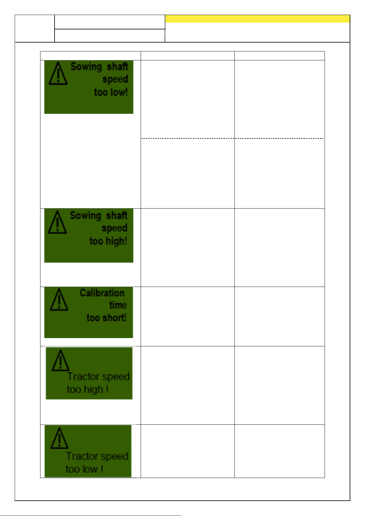
Displayed if the sowing
shaft speed is too low
during calibration
testing.
Use finer seed
metering wheels
• Use fewer seed
metering wheels on
each outlet
• Increase the forward
speed
• Increase the spread
rate
Appears if the PS is
equipped with multiple
device extension cables
in field use and a
potentially necessary
higher drill shaft RPM
cannot be reached.
Use fewer extension
cables
• Check the battery
• Check the plug
connections
• Use larger/coarser
seed metering wheels
to reduce the speed
Displayed if the sowing
shaft speed is too high
during calibration
testing.
Use larger/coarser
seed metering wheels
• Use more seed
metering wheels on
each outlet
• Reduce the forward
speed
• Reduce the spread
rate
Displayed if the
calibration time is too
short.
Press and hold the
calibration button for
min. 20 seconds
Displayed if the driving
speed is too high and
the sowing shaft can no
longer be readjusted.
Reduce the forward
speed
• Use larger/coarser
seed metering wheels
• Use more seed
metering wheels on
each outlet
• Reduce the spread
rate
Displayed if the driving
speed is too low and
the sowing shaft can no
longer be readjusted.
Increase the forward
speed
• Use finer seed
metering wheels
• Use fewer seed
metering wheels on
Page 31
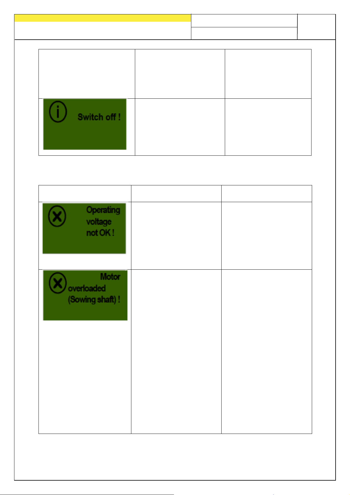
Quality for Professionals
•
Switch off the control
each outlet
• Increase the spread
rate
31
Shown during the shutdown procedure.
Message disappears
after several seconds.
5.2 Fault
Display Cause Solution
Displayed if the
operating voltage falls
below a minimum value
or if there are significant
voltage fluctuations.
Displayed if the sowing
wheel cannot turn or if
the motor is used for
too long at its threshold!
Minimise the
consumption
(e.g. switch off the work
floodlights)
• Check the battery
• Check the cabling
• Check the plugs
• Check the alternator
box!
• Remove any foreign
objects or similar from
the seeding shaft or the
agitator
• Switch off the agitator
(with well-flowing seed)
• Remove 1-3 spacing
discs from the seeding
shaft
• Check the set motor
type. Check the motor
for proper function
while it is idling (switch
off the control box,
remove the motor,
switch on the control
box, switch on the
seeding shaft motor)
Page 32
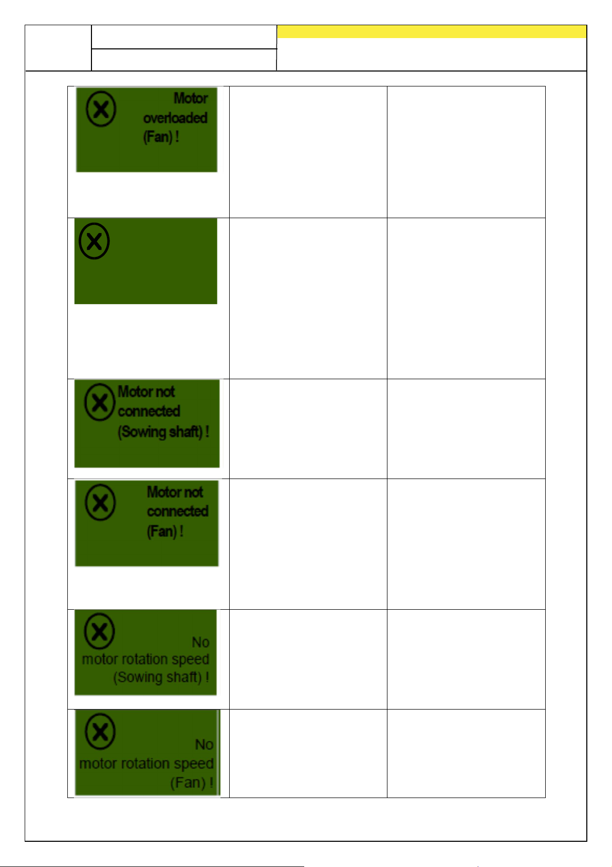
32
•
•
•
•
•
•
Quality for Professionals
Displayed if the motor is
used for too long at its
threshold!
Error
(Fan)!
Displayed when the
hydraulic blower does
not generate air flow
OR when the back
pressure in the tank line
of the motor of the
hydraulic blower is too
big.
Displayed if cables are
not connected or if
cabling is faulty.
Displayed if cables are
not connected or if
cabling is faulty.
Displayed if the motor is
connected and not
overloaded but does
not turn.
Displayed if the motor is
connected and not
overloaded but does
not turn.
Check or install the
calibration lid
• Check if all of the seed
hoses are installed
• Remove any foreign
objects or similar from
the blower fan
• Check the blower fan
for smooth running
Switch on the hydraulic
blower fan.
• There is no pressure
switch installed on the
blower fan, point 7.11
• Replace the return line
filter
• Do not use a reduction
for the tank line (e.g.
BG3 coupling)
• Use a larger tank line
Check if the implement
cable is connected
• Check the cabling
• Check the plugs
If a hydraulic blower fan
is installed, see point
Fehler! Verweisquelle
konnte nicht
gefunden werden.
check if the implement
cable is connected
• Check the cabling
• Check the plugs
Check the clamp
connections on the
spreader
• Please contact
customer service.
Check the clamp
connections on the
spreader
• Please contact
customer service.
Page 33
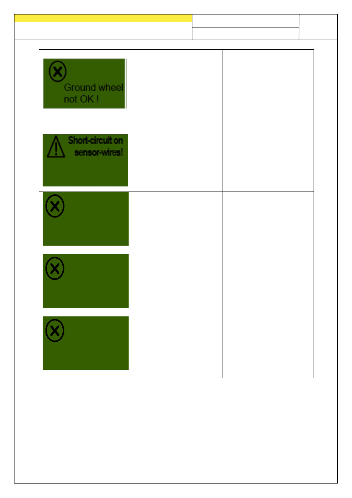
33
•
•
•
•
•
Quality for Professionals
This is displayed when
the control module does
not receive a signal
from the speed sensor!
Displayed if the sensor
power lines are
overloaded or if a short
circuit occurs.
No motor
rotation speed
(spreading disk)!
When the motor is
connected and not
overloaded, but still
does not rotate.
Check the ground
wheel
• Check the sensor
• Check the cabling
• Check the plugs
• If no defects can be
found on the ground
wheel, please contact
customer service.
Check the cables for
damage and shortcircuits
Please contact
customer service.
Motor not
connected
(spreading disk)!
Motor
overloaded
(spreading disk)!
Is displayed when the
wiring is not connected or
is faulty.
Is displayed when the
spreading plate cannot
rotate or when the motor is
strained for too long at its
limits!
Check the cables and
plugs!
Switch off the
implement and check if
there are foreign
objects or similar that
prevents the spreading
disc from rotating
properly!
Page 34
34
•
•
•
•
•
•
•
•
•
•
•
•
Quality for Professionals
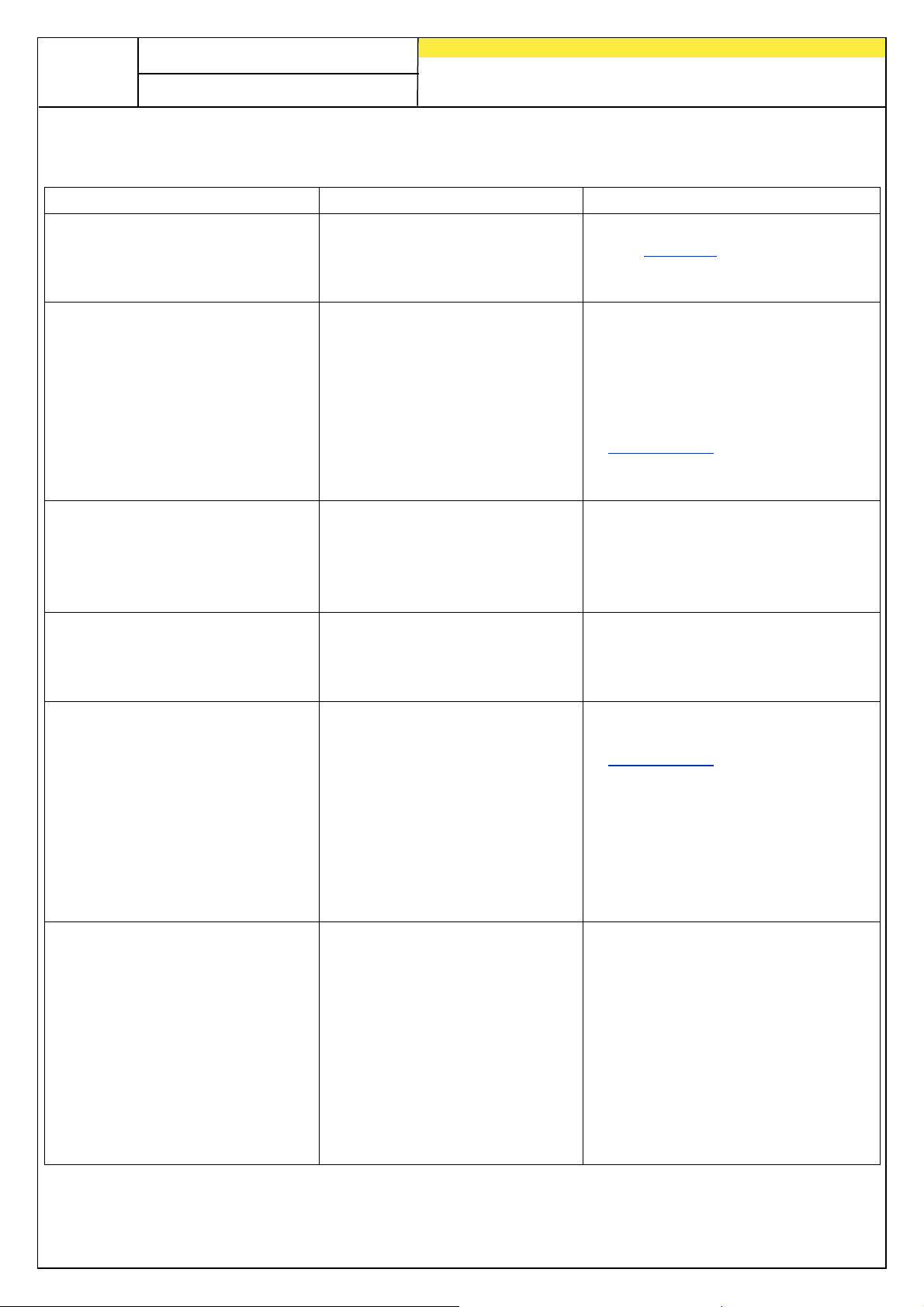
6 Problem solving
Problem Cause Solutions
Seeding shaft rotates when the
implement is lifted!
Seeding shaft does not rotate
when the implement is in
working position!
The fill level sensor is installed,
but does not transmit!
Fill level sensor is constantly
transmitting!
No speed signal!
Wrong lifting unit signal
Seeding shaft is not
switched on
• Forward speed is zero
• No lifting unit signal
No signal from the fill level
sensor
Poor sensor setting
• Poor sensor position
Speed sensor was not
detected
• Wrong speed sensor was
selected
• Y cable (splitter cable)
incorrectly connected
• Y cable (splitter cable)
defective
Invert the lifting unit signal,
see Point 7.8
• Reposition the lifting unit
sensor
Switch on the seeding shaft,
the seeding shaft must be
switched on manually one time
at the beginning
• Check the settings for the
speed sensor
Point 7.3-7.6
• Check the speed sensor
• Check the lifting unit sensor
Adjust the sensitivity of the fill
level sensor (screw on the rear
side)
• Reposition the fill level sensor
• Check the plug and cable
Adjust the sensitivity of the fill
level sensor (screw on the rear
side)
• Reposition the fill level sensor
Check the settings for the
speed sensor
Point 7.3-7.6
• Connect the Y cable properly,
pay attention to the
markings/labels
• Test without the Y cable (only
connect the speed sensor)
No lifting unit signal!
Lifting unit signal is not
detected
• There is no lifting unit signal
emitted on the 7-pin signal
plug of the tractor
• Y cable (splitter cable)
incorrectly connected
• Y cable (splitter cable)
defective
• Magnet sensor: Sensor /
magnet incorrectly installed
Check the lifting unit sensor
• Connect the Y cable properly,
pay attention to the
markings/labels
• Test without the Y cable (only
connect the lifting unit sensor)
• Magnet sensor: the sensor and
magnet must be precisely
opposite to each other when in
working position or in lifted
position
Page 35
Quality for Professionals
•
•
•
•
•
•
•
•
•
•
•
•
35
The control module cannot be
switched on!
The control box is switched off
when the motors are switched
on!
A forward speed of 0.0 km/h is
displayed or it keeps jumping
back to 0.0 km/h!
Spread rate in kg/ha or
seeds/m² is not being
displayed!
Spread rate is too high or too
low!
NOTE:
Check the hectare counter!
Check the speed!
Power cable is not properly
connected
• No supply voltage
• Fuse is defective
Battery is weak, supply
voltage collapses
• Voltage drop due to poor
contact
Wrong speed signal
detected or selected
A valid calibration test was
not performed
• Value was retroactively
changed in the Calibration
test menu
Wrong speed
• Lifting unit sensor switches
during operation
• Seed properties have
changed
Check the plugs
• Check the polarity of the power
cable (pin 15/30 12 V +, pin 31
ground, pin 82 ignition on +)
• Switch on the ignition
• Check the battery
• Replace the fuse
Check the battery voltage
• Check the contacts of the plugs
• Check the power supply cable
Check the speed sensor
settings Point 7.3-7.6, if all of
the settings are on AUTO, then
set the first DIN 9684-1 signal
to NO
Perform a calibration test
• Load the seed type again from
the library
Calibrate the speed sensor (not
required for GPSa sensor)
• Check the lifting unit sensor
• Perform a calibration test
• Reduce the blower fan speed
for the hydraulic blower fan
Return pressure is too high
(blower fan error message)
Line cross-section is too
small
• Cable too long
• Return line filter is clogged
• Constriction in a hydraulic
coupling
Use a larger line cross-section
• Use a new return line filter
• Use a larger hydraulic coupling
Page 36
36
Fig.: 6
Quality for Professionals
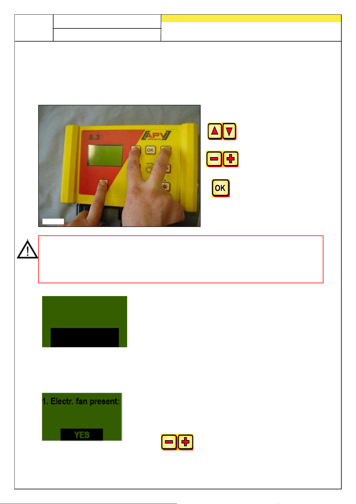
7 Programming 5.2 (customer service)
To call up the programming menu, the following buttons (see figure) must be held
pressed at the same time until the customer service menu appears.
Browse through
programming menu
Modify parameters
Ends and confirms the
programming
NOTE: If a value has been changed in the programming menu and the programming
menu exited, the control box switches off automatically. Then, restart the control box
in order to adopt the changed settings.
If set to
sending signals.
0. Machine type:
AUTO
PS
, the control box automatically detects which sensor is connected and
Select the implement type for which you want to enter the
settings:
PS, MDP, MDG, MDS
7.1 Fan
This menu item is necessary if, instead of an electric fan, a hydraulically or PTO shaft
driven fan is installed.
YES – an electric fan is present
NO – a hydraulic fan is present
Use the buttons to select.
Page 37
Quality for Professionals
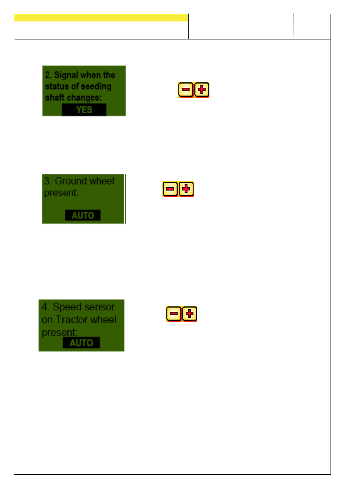
7.2 Signal for switching the sowing shaft on/off (warning tone)
The acoustic warning tone when switching the sowing
shaft on / off can be activated or deactivated here.
Select with the button YES/NO.
7.3 Ground wheel
In this menu item, you can select whether to work with or without a ground wheel.
Use the buttons to select whether
YES/NO/AUTO.
37
7.4 Wheel sensor
Here you can select whether to work with the speed sensor on the tractor or the
feeler wheel.
Using the buttons, select whether
YES/NO/AUTO.
Page 38
38
Quality for Professionals
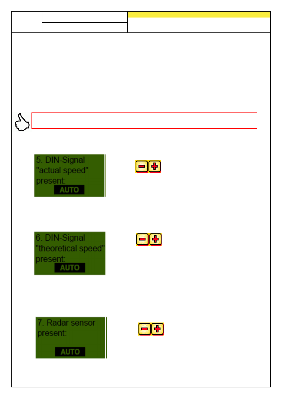
7.5 DIN 9684 signal (7-pin signal socket)
Select whether to work with signals and with which signals are processed by the
tractor.
If present 3 different signals are used:
• Lift unit signal (not wired for all tractors)
• Theoretical speed (from the transmission)
• Actual speed (usually from the radar sensor)
TIP: If both speed signals are present, then the (more exact) actual speed signal will
be preferred.
Specify whether an actual speed signal is available here.
Using the buttons, select whether
YES/NO/AUTO.
Here you can set whether or not a theoretical speed signal is available (PIN 2 on the 7pin signal sockets).
Using the buttons, select whether
YES/NO/AUTO.
7.6 Radar sensor
Select whether to work with or without the radar sensor (or GPSa) here.
Using the buttons, select whether
YES/NO/AUTO.
Page 39
39
Quality for Professionals
7.7 Tractor linkage / Hoisting system
If the device will be operated with the hoisting system signal from the tractor or from a
hoisting system sensor, this must be selected here.
Using the buttons, select whether
YES/NO/AUTO.
7.8 Hoisting system signal
If working with the hoisting system signal from the tractor or the tractor linkage /
hoisting system, the position of the hoisting system sensor can be set here. The
position of the sensor can be inverted here and adjusted to the data.
Using the buttons, select whether
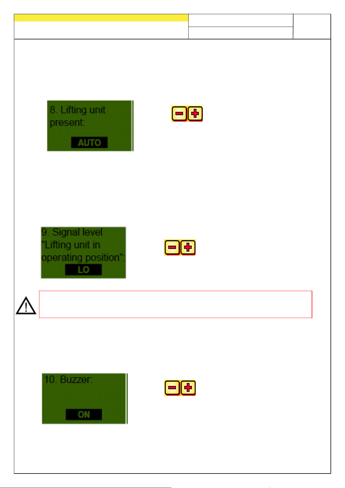
HI or LO.
NOTE: If your PS is sowing from the incorrect hoist position, for example, the position
can be adjusted here.
7.9 Buzzer (warning signal)
This menu item is used to set whether you wish to work with an audible buzzer (e.g.
warning signal in the case of fault messages) or without this support.
Using the buttons, select whether
ON or OFF.
Page 40
40
Quality for Professionals
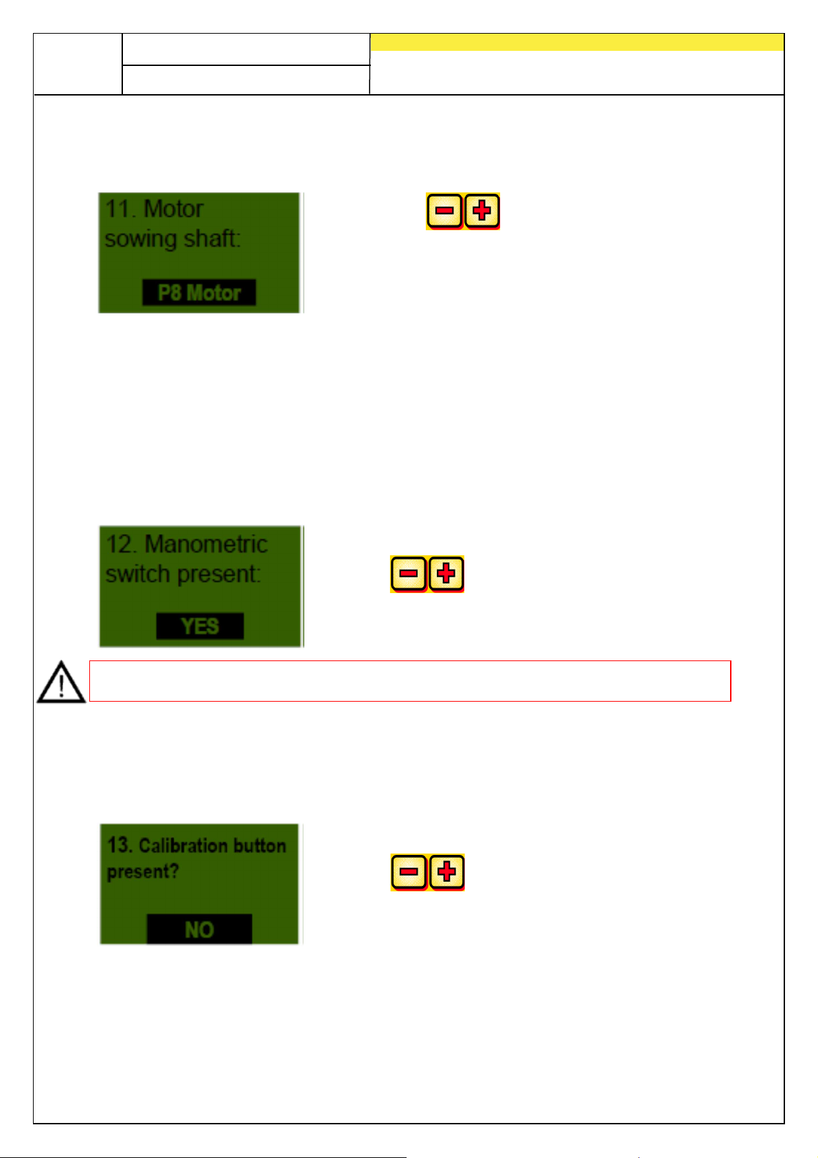
7.10 Sowing shaft motor
The drive motor to be controlled is selected here.
Using the buttons, select one of the
following
P8 motor (installed on the PS 120-500 and all
MDP, MDG, MDS)
P16 motor (installed on the PS 800 until serial
number 04011-01299)
P17 motor (installed on the PS 800 with serial
numbers higher than 04011-01300 and
PS 1200, PS 1600)
7.11 Pressure sensor
Whether your PS has a pressure sensor (measures the air current from the hydraulic
fan) is set here.
Using the buttons, select whether
YES or NO.
NOTE: Installed as a standard on all PS with hydraulic blower fan as of 2017.
7.12 Calibration button present
Here you specify whether a calibration button is installed on your PS.
Using the buttons, select whether YES or NO.
7.13
Page 41
Quality for Professionals
7.13 Measuring units
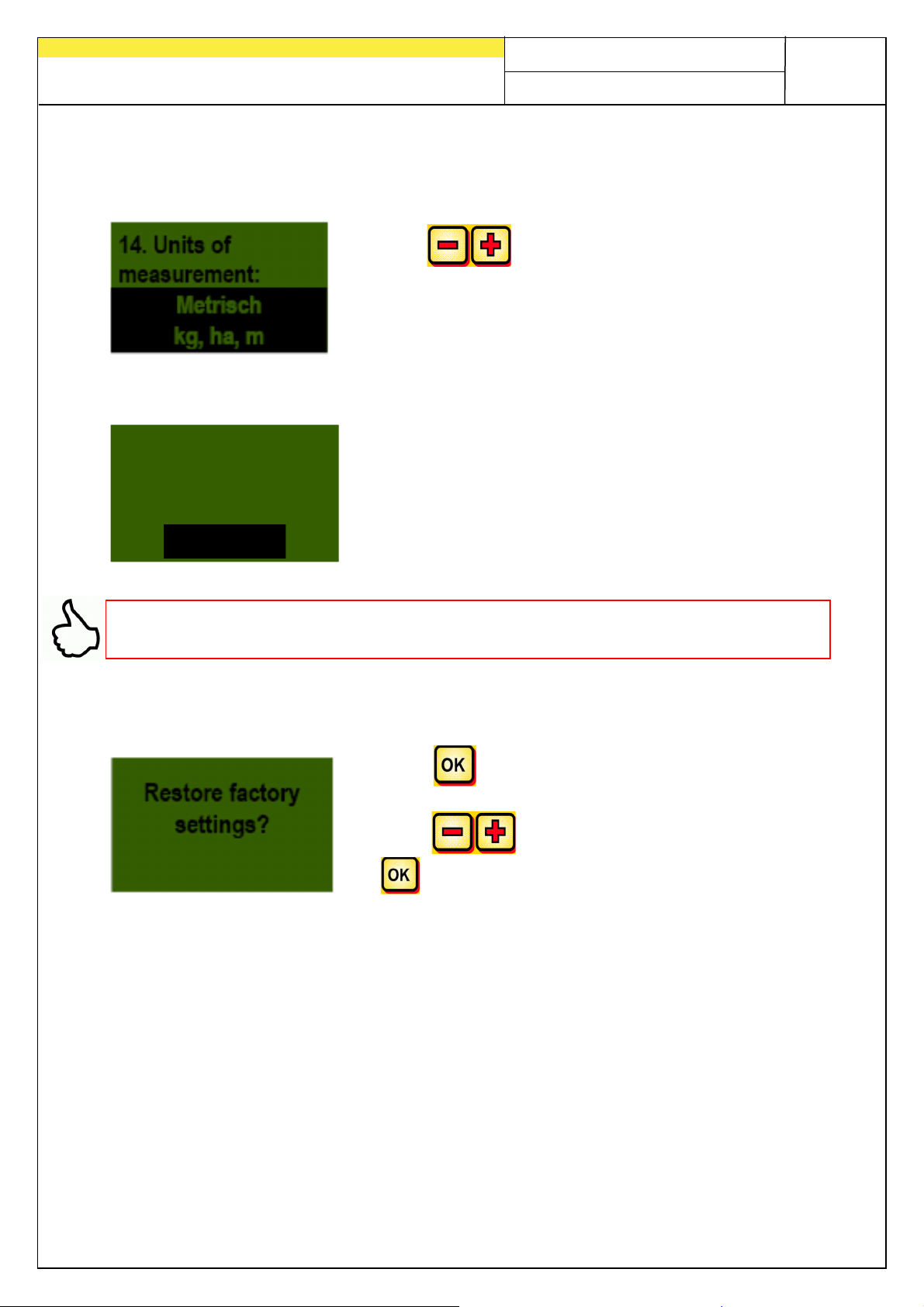
Metric units (m, ha, km/h, kg) may be set to imperial units (ft, ac, mph, lb) here.
Using the buttons, select whether Metric or
Imperial.
7.14 Implement type
15. Prompt for
machine type
at startup ?
NO
TIP: if you are using the same controller to operate several different types, you
therefore do not need to enter the programming menu every time to change the type!
Here, you can set whether the controller should request
the used implement type (PS, MDP, MDG, MDS) every
time the controller is switched on.
41
7.15 Restore factory settings
Press the button.
Using the buttons, select YES and then press
the button anew.
The set language, total hours, and total area remain unchanged.
Page 42
42
Fig.: 7
Quality for Professionals
8 Accessories
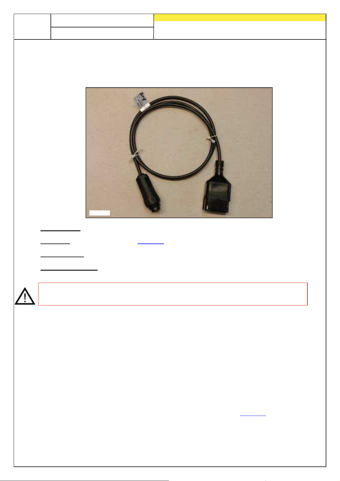
8.1 7-pin signal cable (item no.: 00410-2-006)
Connection: 12-pin connector on the control module
Settings: see under point 7.5
Cable length: 1.5 m
Scope of delivery: 1 7-pin signal cable
NOTE: The signal socket is not completely wired for tractor manufacturers, even if it
is mounted in the cab.
A connection from the tractor to the control module can be made using the 7-pin
signal cable. Three signals pass through this cable from the tractor to the control
module (DIN 9684 standard). This transmits the actual driving speed [km/h] and the
lifting unit signal from the tractor to the control module. This is displayed on the
control module and the seed volume is automatically regulated by the sowing shaft
speed control.
This means that the required volume of seed per hectare is always maintained, even
if the driven speed deviates slightly from the speed specified in the calibration test.
All processes such as control and checking are provided to the user during the work
process by the control module. Because of the hoisting system signal, you do not
need to manually operate the control module, even when making turns. On some
tractors, the hoisting system signal is inverted. If the sowing shaft turns as soon as
the hoisting system is lifted out, then proceed as described under point 7.8.
Page 43
43
Fig.: 8
Quality for Professionals
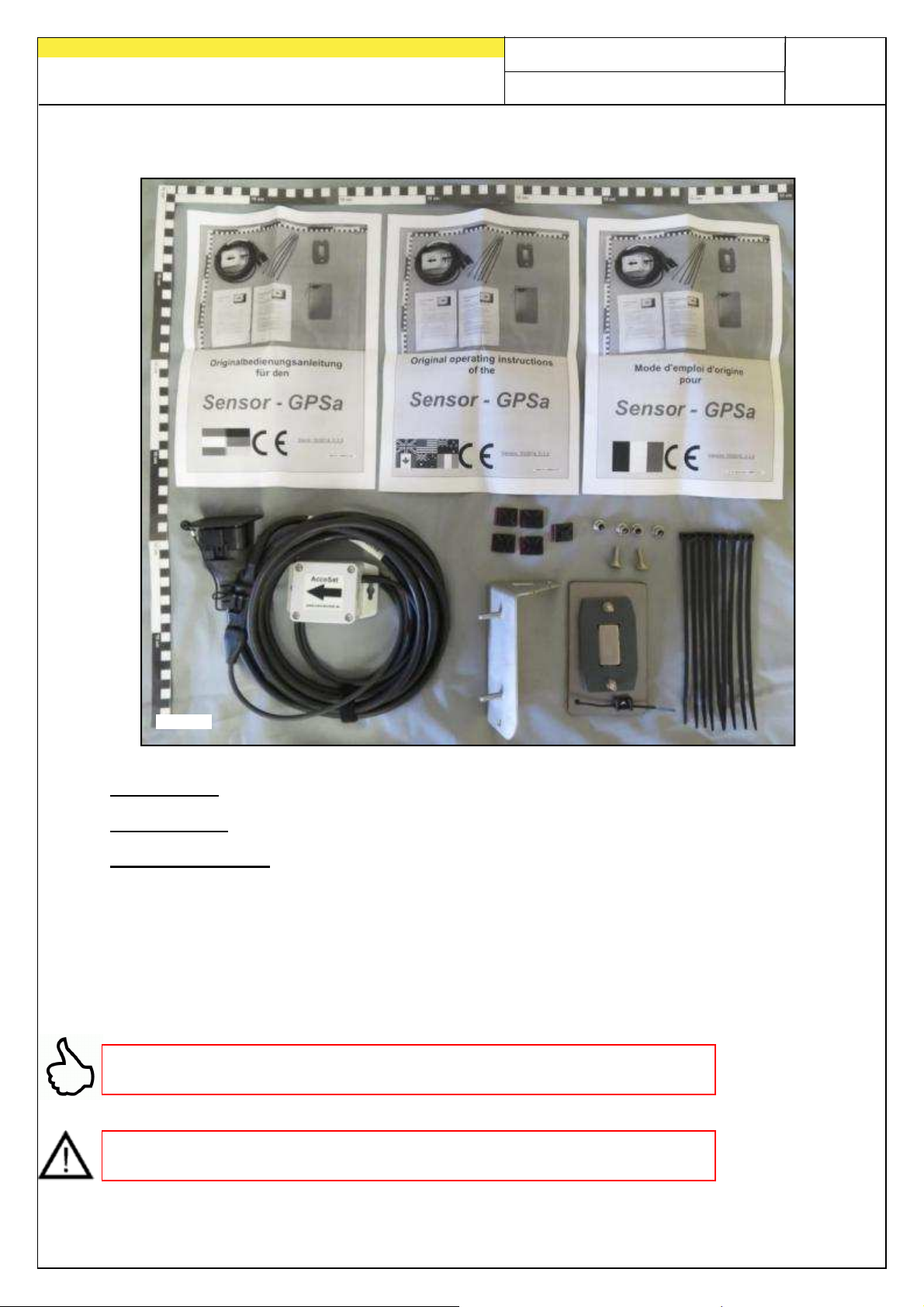
8.2 Sensor GPSa (item no.: 00410-2-107)
Connection: 12-pin connector on the control module
Cable length: 5 m
Scope of delivery: 1 GPSa sensor, datasheet, mounting plate incl. mounting
equipment
The GPSa sensor transmits the current vehicle speed to the control module. The
current speed is measured by the combination of a GPS unit and a 3D acceleration
sensor. As a result, the sensor responds extremely fast to changes in speed. Plus,
the sensor only needs to be mounted horizontally on the top of the machine.
TIP: It does NOT need to be calibrated!
NOTE: The sensor does not function if the GPS unit is in a blind spot.
Page 44
44
Fig.: 9
Fig.: 10
Fig.: 11
Quality for Professionals
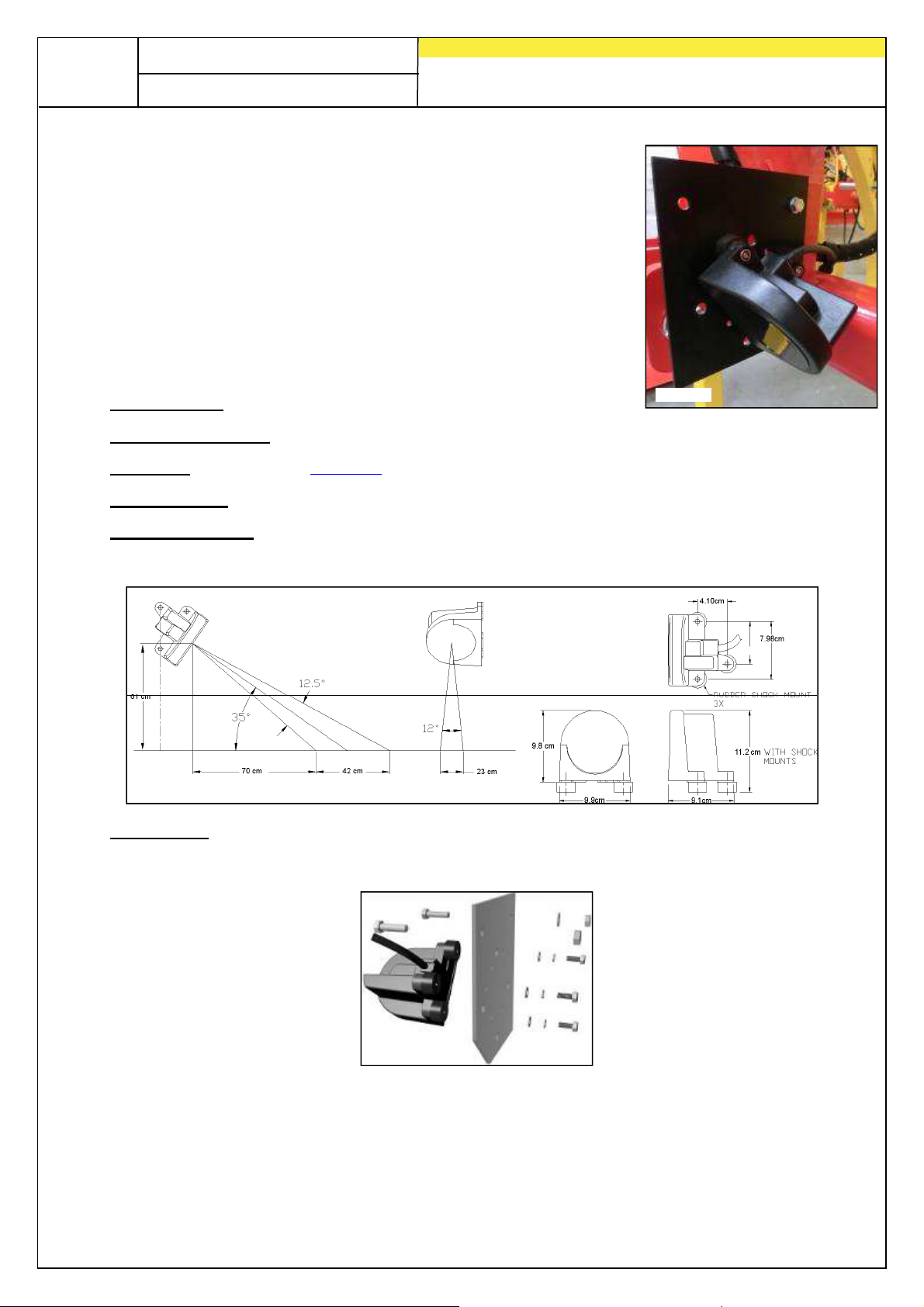
8.3 Radar sensor MX35 (item no.: 00410-2-084)
The radar sensor measures the driving speed [km/h]. This is
displayed on the control module and the seed volume is
automatically regulated by the sowing shaft speed control. This
means that the required volume of seed per hectare is always
maintained, even if the driven speed deviates slightly from the
speed specified in the calibration test.
Connection:
Scope of delivery: 1 radar sensor, 1 installation plate incl. fastening material
Settings: see point 7.5
Cable length: 5 m
1-pin connector on the control module
Where installed: Should be between the wheels. See illustrations below for
alignment and attachment dimensions (35° in the direction of
travel or opposite).
Installation: To fasten the radar sensor, please use the screws/bolts, nuts
and the mounting plate provided in the scope of delivery.
The radar sensor works on almost all surfaces (e.g. earth, sand, asphalt, etc.). The
radar sensor's detection can become imprecise in the event of snow or thick layers of
ice or if the on-board voltage falls below 9 V.
Page 45
45
Wheel
diameter in mm
250 500 1000
1500
2000
Fig.: 12
Quality for Professionals
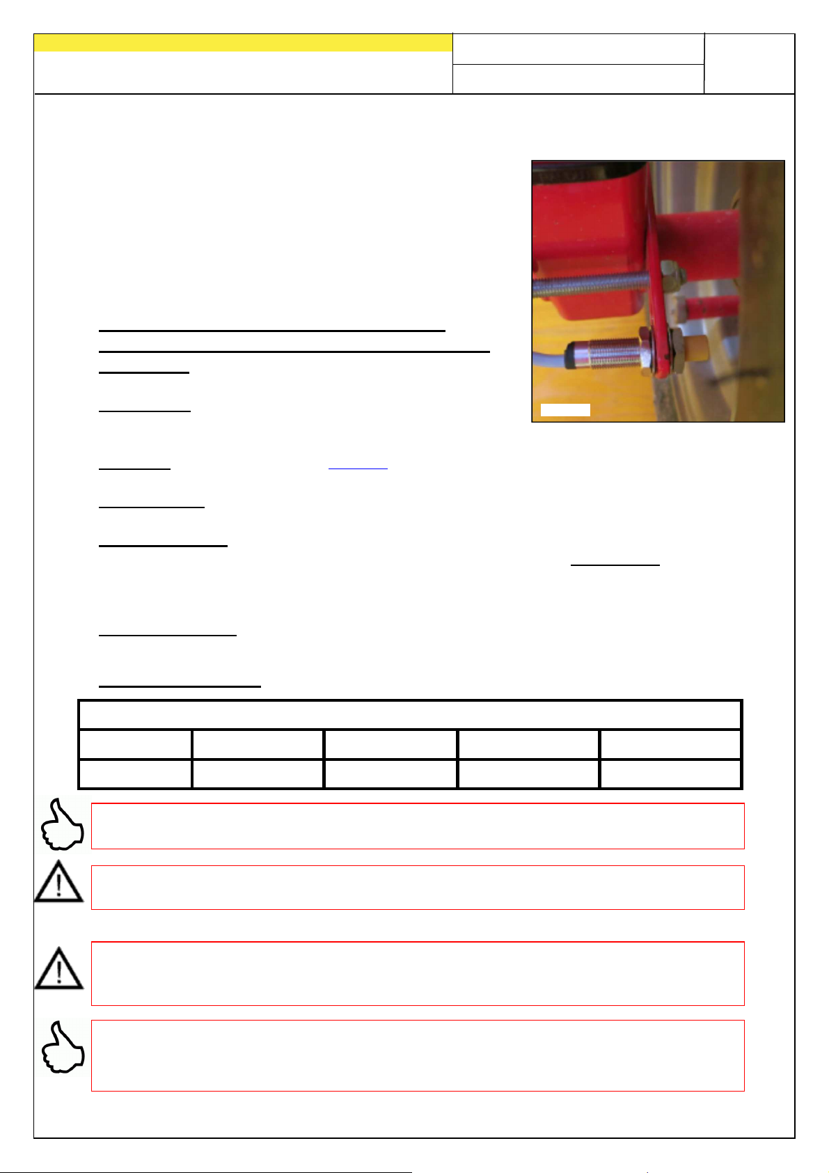
8.4 Wheel sensor (item no.: 00410-2-007)
The wheel sensor measures the driving speed [km/h].
This is displayed on the control module and the seed
volume is automatically regulated by the sowing shaft
speed control. This means that the required volume of
seed per hectare is always maintained, even if the
driven speed deviates slightly from the speed specified
in the calibration test.
The sensor can detect both the magnets
provided and all metals (screw heads, wheels
bolts, etc.)
Connection: 12-pin connector on the control
module
Settings: See under item 7.5
Cable length: 5 m
Where installed: The magnet is installed on the inside of the wheel rim. The
sensor must be fastened at a distance of max. 5 mm from the
magnets (or wheel bolts, nuts, etc.). If the sensor is actuated, the
Scope of delivery: 1 sensor and 2 fastening nuts, 8 neodymium magnets (very
Number of magnets:
LED on the rear side illuminates.
strong), cable ties, 1 fastening plate
1 magnet 2 magnets 4 magnets 6 magnets 8 magnets
TIP: To align the 6 magnets optimally, it is best to use a circle (e.g. string) to make a
uniform hexagon.
CAUTION: Keep the neodymium magnet away from the heart. This can affect the
function of cardiac pacemaker!
NOTE: Screws/bolts must not be used to fasten the magnets. The strong magnetic
force holds the magnet to steel wheel rims. To prevent possible damage to the cable
(e.g. caused by the wheel), lay it out so that it is effectively protected.
TIP: Do not mount the wheel sensor on the power train, since the speed is too high
there and this may result in errors!
There may not be more than 15 pulses/m.
Page 46
46
Fig.: 13
Quality for Professionals
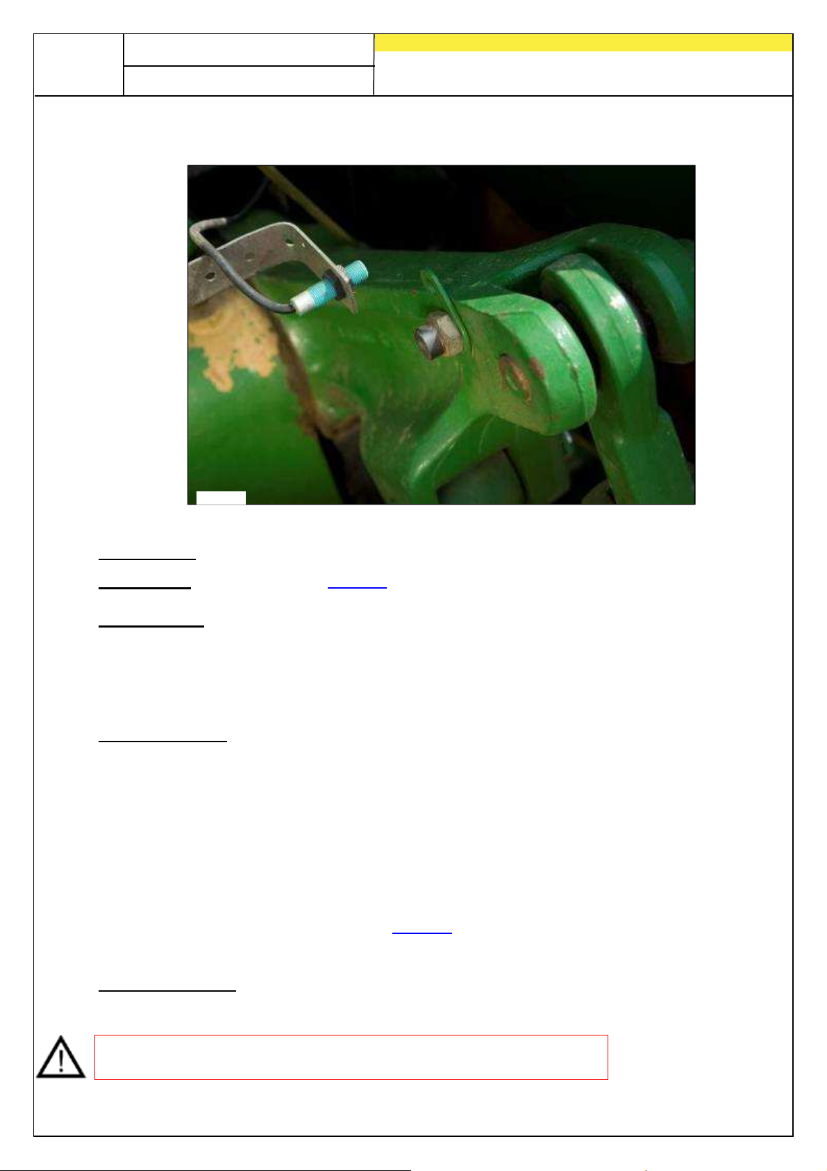
8.5 Tractor linkage lower bar sensor (item no.: 00410-2-008)
Connection: 12-pin connector on the control module
Calibration: See under item 7.7
Cable length: 5 m
Thanks to this sensor, the sowing shaft of the PS can automatically unlock and stop
when the working tool is raised or lowered.
Where installed: Because most tillage implements are raised and lowered when
being used, it is best to install the sensor at, or on, the tractor's
lever arm (see figure above). The sensor can also be installed
elsewhere where there is a mechanical movement of more than
50 mm. There should be a distance of at least approx. 5 mm
between the sensor and the magnet. For coupled tillage
implements, the sensor can be installed on the chassis. because
the hoist is not being used here. The programming (for the
position in which work is to be carried out) can be adjusted for
this.
This is explained in item 7.8 .
Scope of delivery: 1 sensor, 2 magnets incl. screws/bolts, cable binders, 1 fastening
plate, 2 PVC nuts for the sensor
NOTE: The sensor must not be screwed on too tightly (tensioned)!
Page 47
Quality for Professionals
Fig.: 14
Fig.: 15
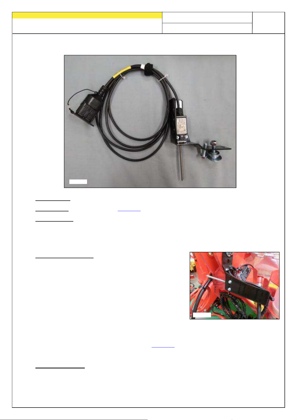
8.6 Tractor linkage upper bar sensor (item no.: 00410-2-074)
Connection: 12-pin connector on the control module
47
Calibration: See under point 7.7
Cable length: 3 m
Thanks to this sensor, the sowing shaft of the PS can automatically unlock and stop
when the working tool is raised or lowered
Installation location: Because most tillage
implements are raised and
lowered when being used, it is
best to install the sensor on the
tillage implement's three point.
The sensor can also be
installed elsewhere where there
is mechanical movement. For
coupled tillage implements, the
sensor can be installed on the
chassis. because the hoist is not being used here. The
programming (for the position in which work is to be carried
out) can be adjusted for this.
This is explained in point 7.8.
Scope of delivery: 1 sensor,
1 fastening plate incl. screws/bolts
Page 48
48
Fig.: 16
Quality for Professionals
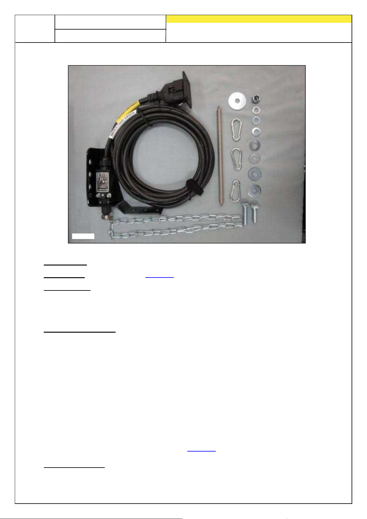
8.7 Tractor linkage pull switch sensor (item no.: 00410-2-115)
Connection: 12-pin connector on the control module
Calibration: See under point 7.7
Cable length: 5 m
Thanks to this sensor, the sowing shaft of the PS can automatically unlock and stop
when the working tool is raised or lowered.
Installation location: Using a spring (for length compensation) and a chain, it is
possible to connect two points - which move relative to each
other during machine lifting. The switch is actuated by the
change in length, thus switching off the sowing shaft. Similarly
to the tractor linkage sensor upper link, the pull switch can be
mounted on the three-point and tensioned with the chain, e.g. at
the coupling device on the tractor. If the machine is now lifted
out, the path between the two points becomes longer and the
pull switch switches the sowing shaft off. However, the switch
can also be mounted parallel to the cylinders, in parallelograms,
etc., whereby a relative movement takes place between two
points during the lifting process. Whether sowing is to be
carried out with actuated or non-actuated switch, can be
defined in the programming.
This is explained in point 7.8.
Scope of delivery: 1 sensor,
1 fastening plate incl. screws/bolts
Page 49
Quality for Professionals
Fig.: 17
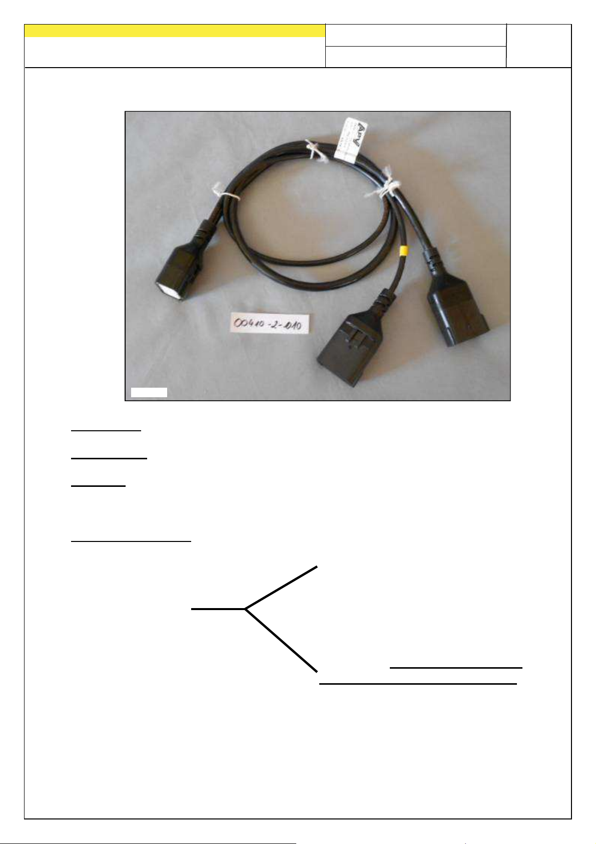
8.8 Splittercable (item no.: 00410-2-010)
Connection: 12-pin connector on the control module
Cable length: 1 m
Function: This is required when working with 2 sensors (e.g. with the wheel
sensor and with the hoist sensor).
Connection diagram:
Speed sensor
12-pin sensor for
the control module
Hoist sensor
the label (lifting unit / linkage)
yellow marking with
49
Page 50
50
Fig.: 18
Quality for Professionals
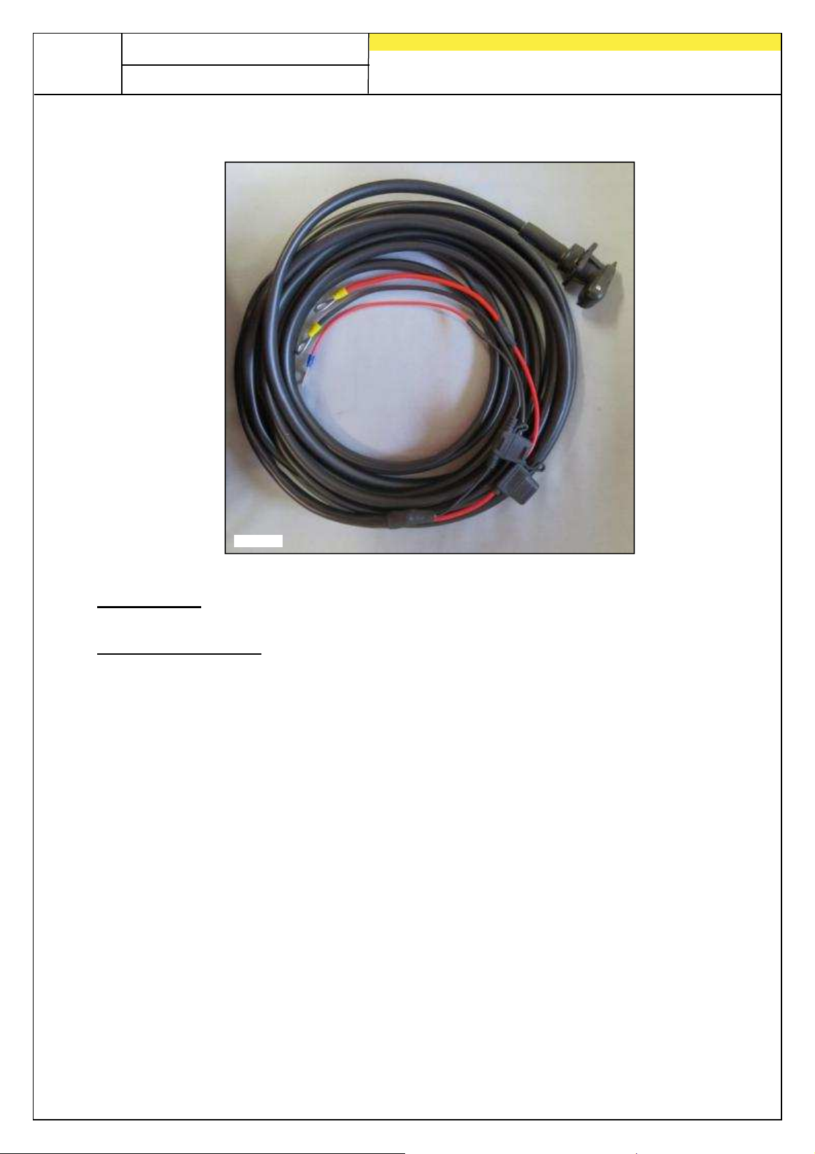
8.9 Set of adapter cables for tractors (item no.: 00410-2-022)
Cable length: 8 m
Connection diagram: Red (6 mm² cable) = 12 Volt
Red (2.5 mm² cable) = Ignition plus
Black (6 mm² cable) = Ground
A retrofit kit is available as an accessory for the control module power supply
equipped without the standard 3-pin socket on the tractor. This is a 8 m long cable.
At the battery, this is screwed right to the battery terminals, a standard 3-pin socket is
mounted at the other end.
Page 51
Quality for Professionals
Fig.: 19
Fig.: 20
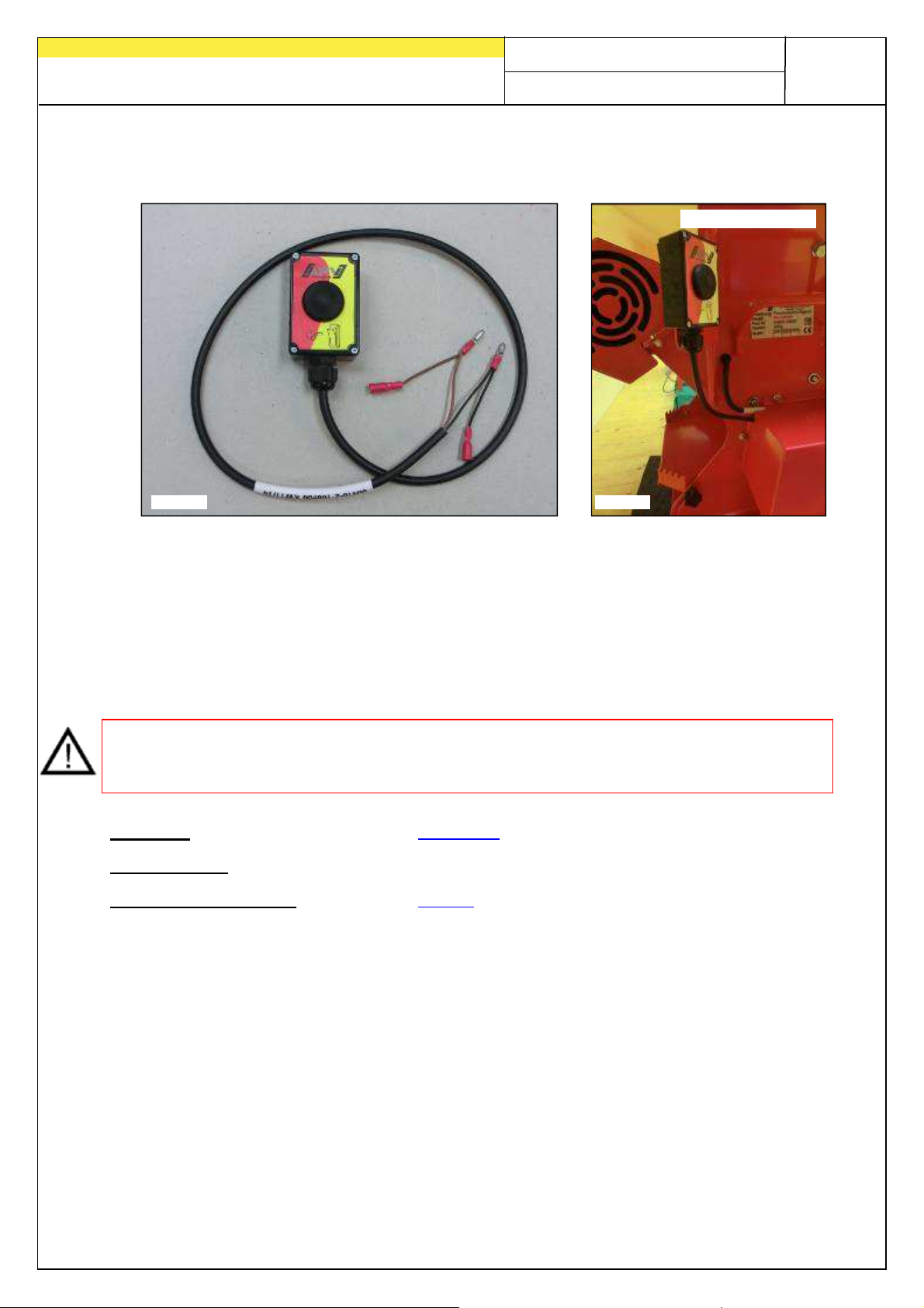
8.10 Calibration button (item no.: 00410-2-094)
51
Installation example
The calibration button is integrated directly with the wiring harness of the pneumatic
sowing shaft and is easily mounted on the device using the integrated magnets.
Calibration testing may be started with this if you are standing at the device, calibration
takes place for arbitrary periods, and the container is also being emptied. As soon as
the calibration test has been started at the control module and you activate the
calibration button, the sowing shaft will start to turn. The calibration process lasts until
the calibration button is released again. Next, the controller calculates the required
application quantity, which then needs to be weighed and input into the menu.
NOTE: In order to achieve corresponding exactness, the calibration button must be
held down for at least 20 seconds, otherwise the message "Calibration time too
short!" will appear and the kg/ha or grains/m² will not be shown in the main display.
Settings: see under point 7.12
Cable length: 1 m
Connection diagram: see under point 9
Page 52
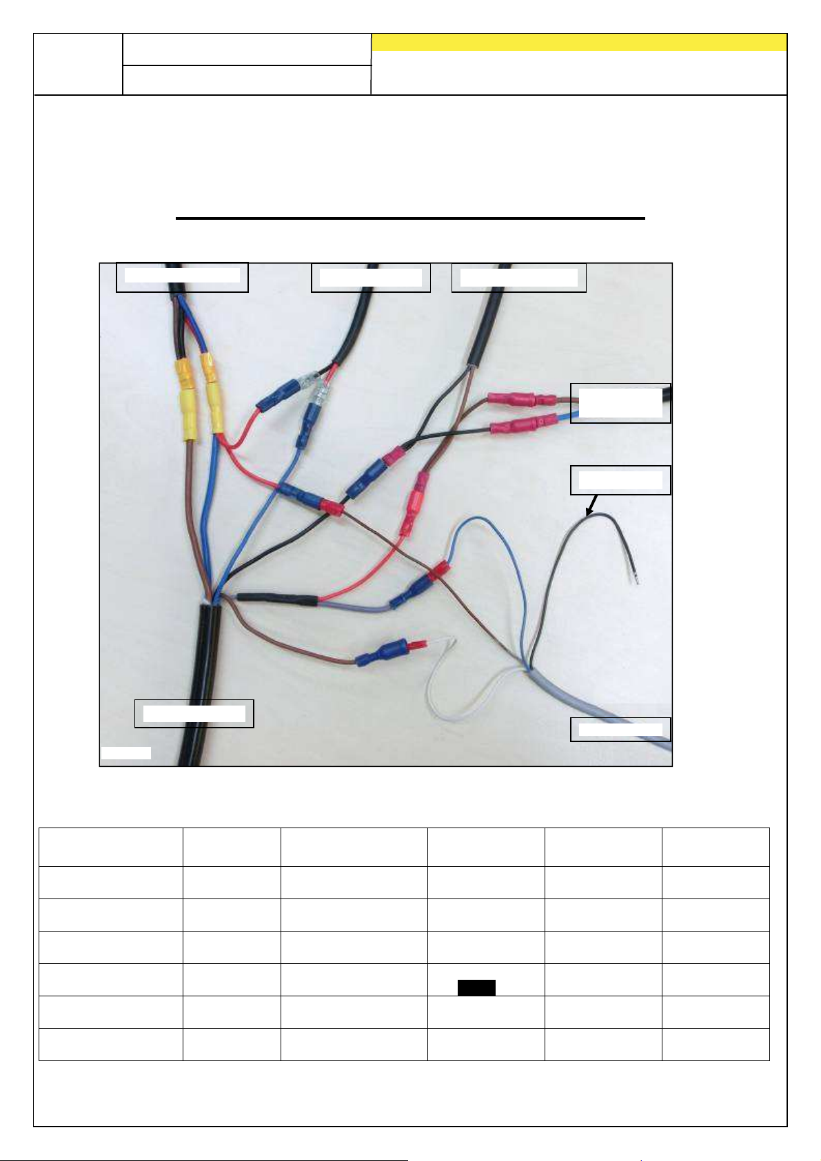
52
Device cable
Drive
Fan
Pressure
Fill level
Calibration
2,5 mm²
2,5 mm²
Fan motor
Fig.: 21
Pressure
Fill level
Quality for Professionals
9 Connection diagrams
9.1 PS connection diagram
Connection diagram PS 120-500 MX
Circuit diagram up to model year 2014 (no terminal strip on the spreader)
Drive motor
Calibration button
switch
PS MX 3
4 mm² / Blue
PS device cable
motor
1,5 mm² /
Black
motor
Red/Blue
switch
0,75 mm²/
Brown
Not used
sensor
button
4 mm² / Brown
1,5 mm² / Blue
1,5 mm² / Brown
1,5 mm² / Black
1,5 mm² / Grey
1,5 mm² /
Red
Black/Brown
0,75 mm² /
White
0,75 mm² /
Blue
1,5 mm² /
Brown
1,5 mm² /
Blue
0,75 mm² /
Black
0,75 mm² /
Brown
Page 53
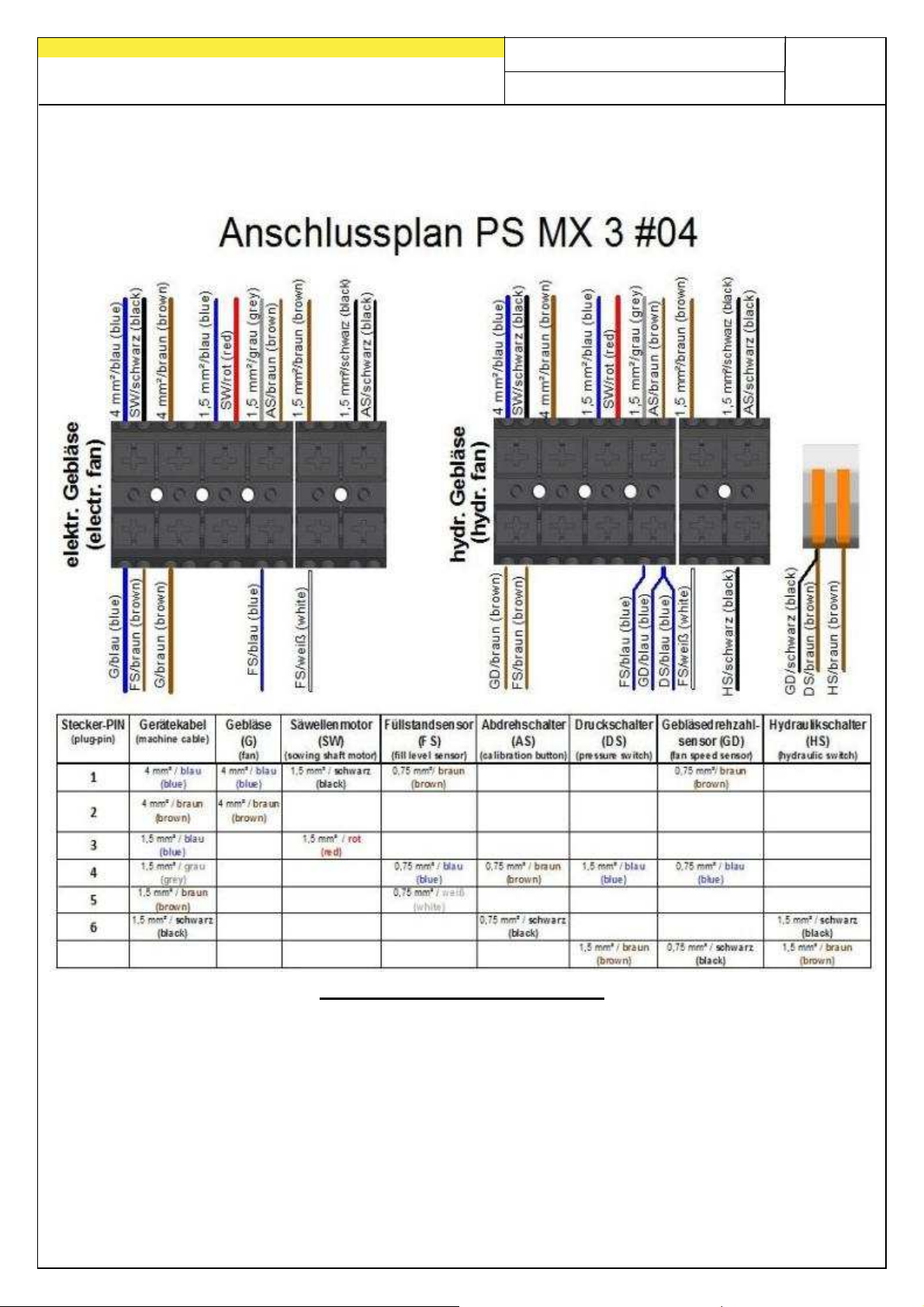
Quality for Professionals
Fig.: 22
Connection diagram as of model year 2015 (with terminal strip on the
spreader)
53
Stripping length 10 mm!
Page 54
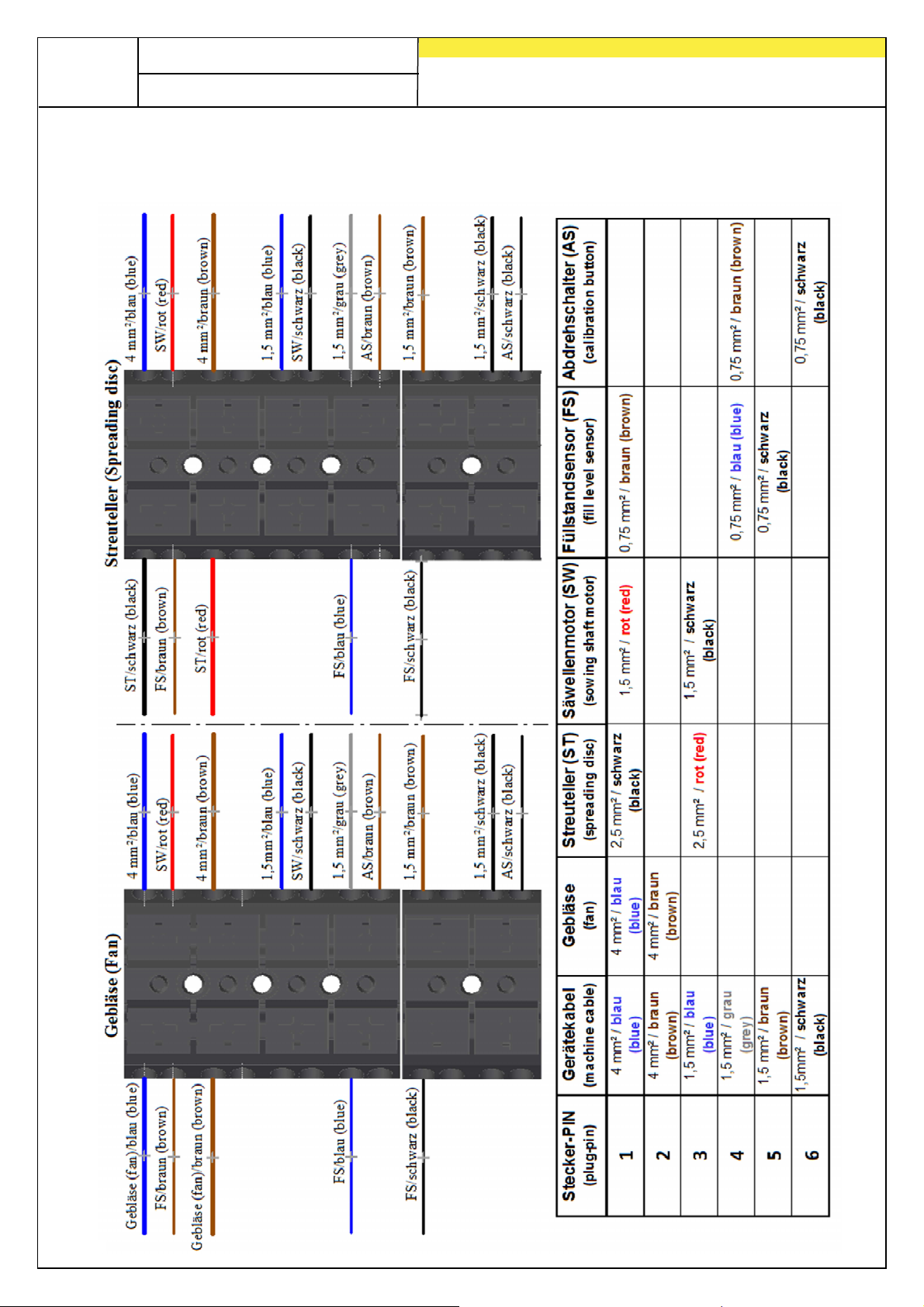
54
Fig.: 23
Quality for Professionals
9.2 MD connection diagram
MD MX#01 connection diagram
Page 55
Quality for Professionals
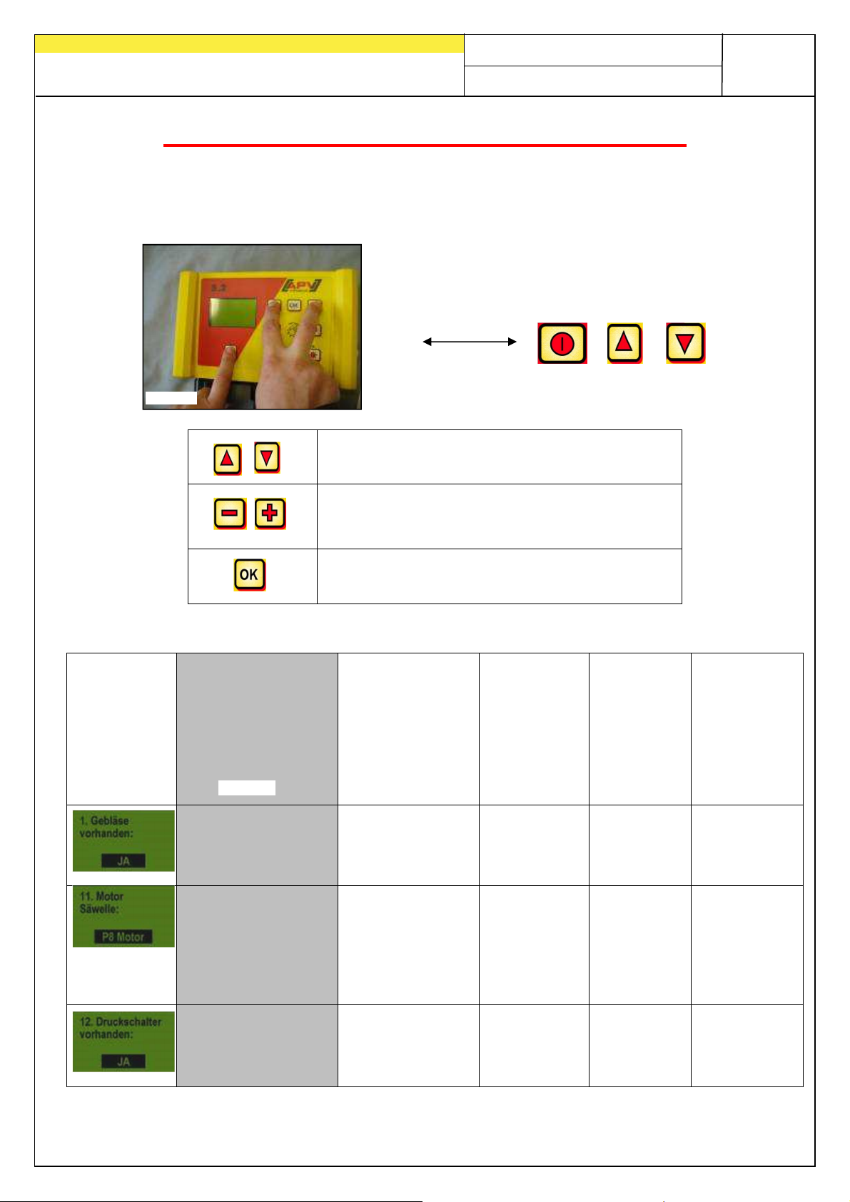
Calls up the programming menu.
P16 motor
Fig.: 24
Adjustments for PS with hydraulic blower fan
For electrical blower fans, this sheet can be ignored.
If your PS is equipped with a hydraulic blower fan, the control module must
first be set for your specifications before initial operation.
By pressing the following buttons
simultaneously:
The following changes must be made on your 5.2 control module depending on the implement
type:
- Scrolls in the programming menu
- Changes the parameter
- Exits and saves the programming
55
PS 120 M1
PS 150 M1 (expired)
PS 200 M1
PS 250 M2 (expired)
PS 300 M1
PS 500 M1 / M 2
ELECTRICAL
BLOWER FAN
is pre-set
YES NO NO NO NO
P8 motor P8 motor
NO YES YES YES YES
PS 500 M1 / M2 H
HYDRAULIC
BLOWER FAN
PS 150 M1
H (expired)
PS 200 M1 H
PS 250 M2
H (expired)
PS 300 M1 H
PS 800 M1
Up to SN:
04011-
01299
P17 motor
As of SN:
04011-01300
PS 1200
PS 1600
P17 P8 motor
Retrofitting
an HG 300
M1
Page 56

Quality for Professionals
Inspired by farmers & realized by professionals
APV - Technische Produkte GmbH
HEADQUARTER
Dallein 15
AT-3753 Hötzelsdorf
Tel.: +43 (0) 2913 8001
Fax: +43 (0) 2913 8002
www.apv.at
 Loading...