

Page 1
Translation of the
original operating manual
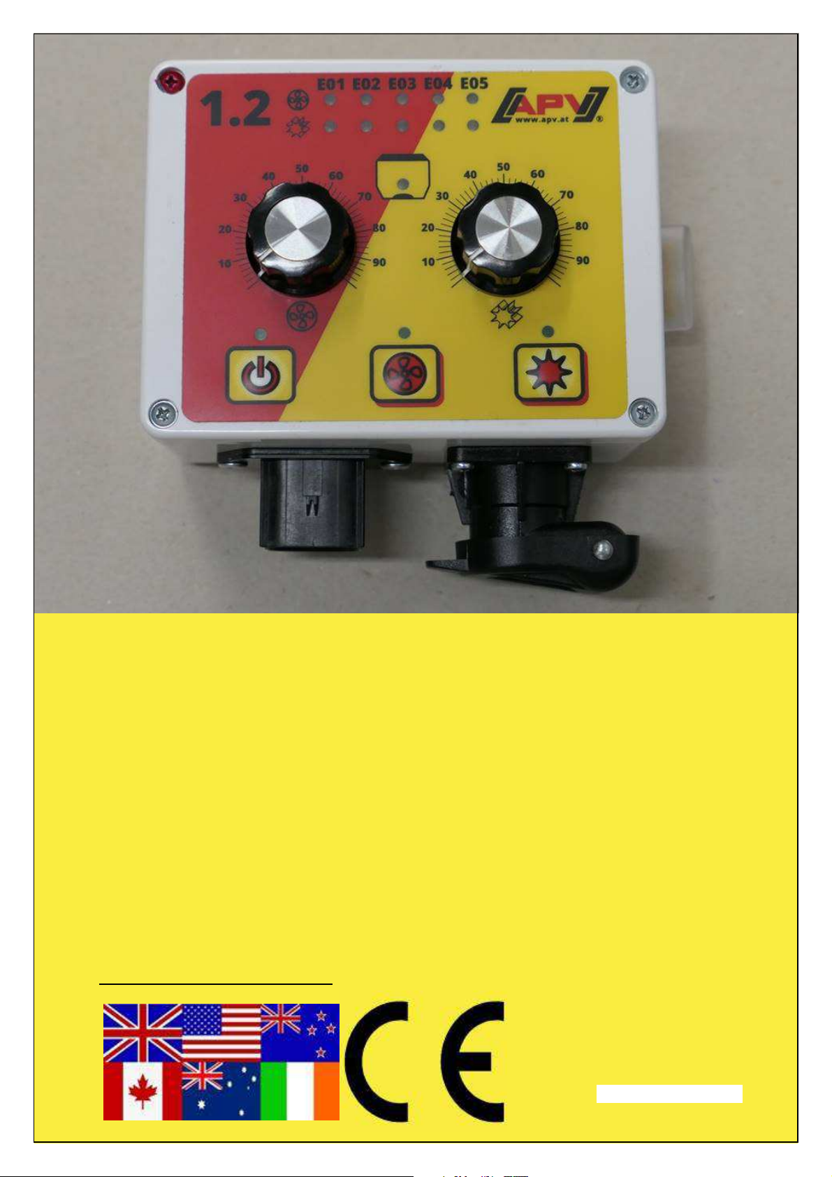
1.2
Read carefully before initial operation!
Version: 12/2018, V.1.2
Order no.: 00601-3-135
Page 2
2
Quality for Professionals
It may NOT
seem inconvenient and unnecessary to read and
observe the operating instructions. It is not enough
to hear and see from others that an implement is
good, and then to buy it and believe that everything
takes care of itself. The person concerned would
then not only cause damage to himself, but also
make the mistake of assuming that the cause of any
problems is due to the implement, instead of
himself. To ensure success, one has to go into the
spirit of things, and instruct oneself about the
purpose of all equipment on the implement and gain
experience with its handling. Only then can one be
satisfied both with the implement and oneself. These
operating instructions aim to achieve this.
Leipzig-Plagwitz 1872
Page 3
3
Quality for Professionals
Table of contents
1 Warranty .............................................................................................................. 4
2 Quick start ........................................................................................................... 4
2.1 Scope of delivery and attachment ................................................................. 4
2.2 Electrical connection ...................................................................................... 5
2.3 User interface of the control box .................................................................... 6
2.4 Starting up the implement .............................................................................. 7
2.5 Operation on the field .................................................................................... 7
2.6 Calibration test .............................................................................................. 7
2.7 Emptying the hopper ..................................................................................... 8
2.8 Spreading disc speed chart ........................................................................... 8
2.9 Automatic implement shut-off ........................................................................ 8
3 Status messages and possible solutions ............................................................. 9
3.1 Controller messages ...................................................................................... 9
3.2 Assistance in the event of problems ............................................................ 10
4 Cleaning ............................................................................................................ 10
5 Decommissioning, storage and disposal ........................................................... 10
5.1 Decommissioning the implement ................................................................. 10
5.2 Storage ........................................................................................................ 10
5.3 Disposal ....................................................................................................... 10
6 Accessories ....................................................................................................... 11
6.1 Tractor cable set (Item no.: 00410-2-022) ................................................... 11
7 Programming menu ........................................................................................... 12
7.1 Blower fan / spreading plate ........................................................................ 12
7.2 Seeding shaft motor .................................................................................... 13
Page 4
4
bracket
Quality for Professionals
1 Warranty
Please check the implement for any transport damage immediately upon receipt.
Later claims regarding transport damage can no longer be considered.
We provide a one-year factory warranty as of the date of delivery (your invoice or the
delivery slip serve as a warranty certificate).
This warranty is applicable for cases of material or construction faults and does not
include parts that are damaged by normal or excessive wear.
The warranty expires
− if damage is caused by external forces (e.g. opening of the controller),
− if the control box is opened,
− in cases of operating errors,
− if the prescribed requirements are not met,
− if the implement is modified, expanded or equipped with third-party spare parts
without our permission.
2 Quick start
2.1 Scope of delivery and attachment
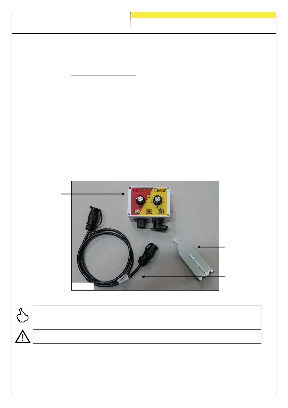
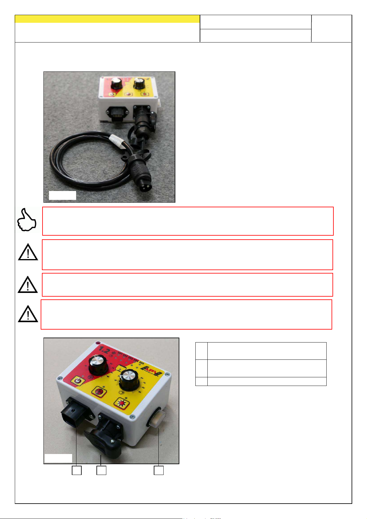
Control box
Fasten the standard supplied bracket with two bolts in the tractor cab.
TIP: Pay attention to the angle at which you look at the control module, to be able to
read the display optimally. If necessary, bend the bracket slightly to adjust the angle
as required.
CAUTION: if possible, do not roll up the cable into a coil!
Fig.: 1
Control box
Power cable
Page 5
2 3
Quality for Professionals
2.2 Electrical connection
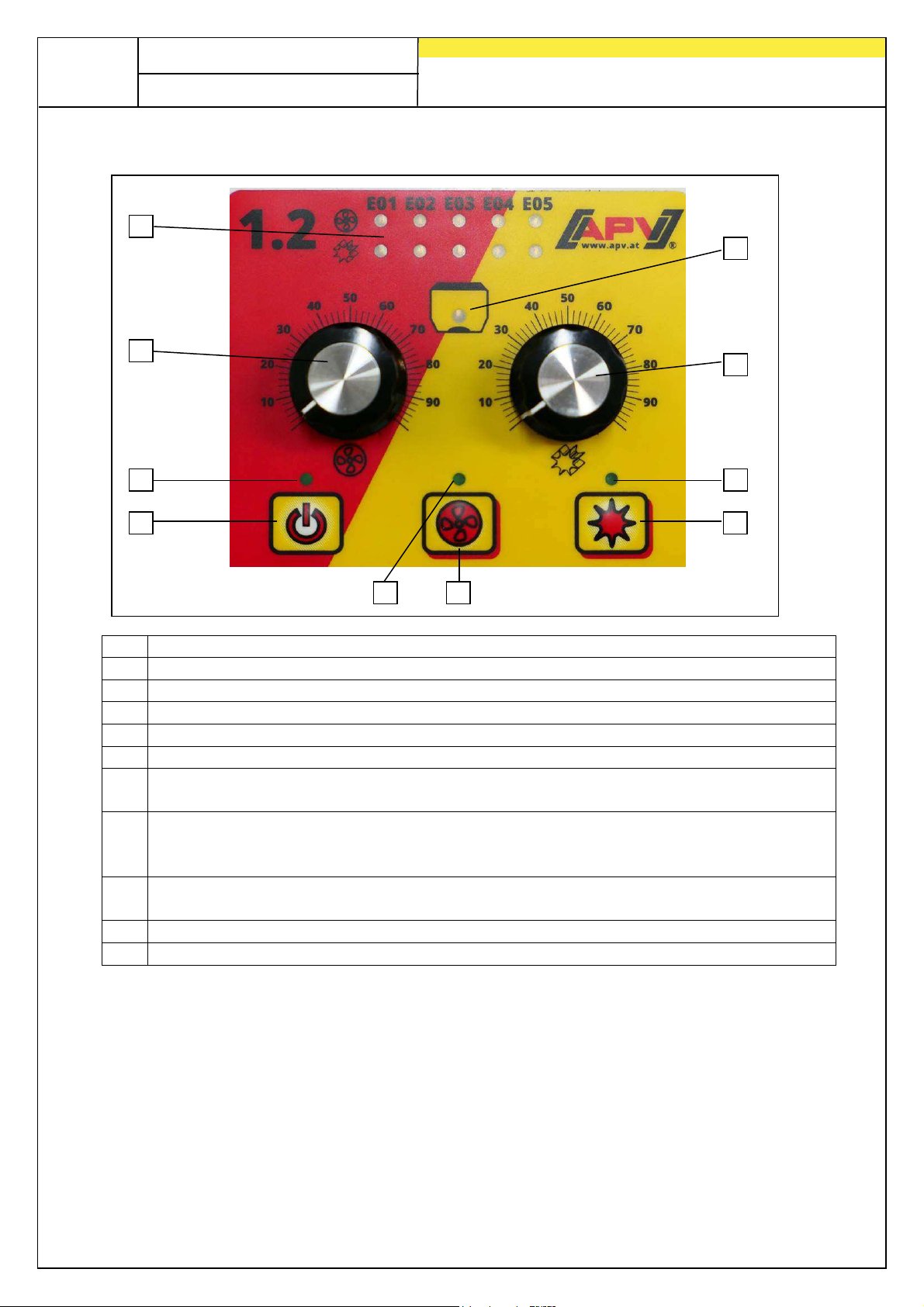
The standard supplied cable can be
directly connected to the 3-pin standard
socket of the tractor in the cab. The other
end is connected to the control box.
The fuse (25 A) is located on the right side
of the control box.
Stow the excess cable in the driver's cab to
avoid pinching.
Fig.: 2
TIP: If your tractor does not have a standard socket, it can be fully retrofitted with the
complete cable set for power socket, tractor retrofitting, 8-m long (item no. 00410-2-
022) (accessory).
IMPORTANT INFORMATION:
The 12 volt power supply must NOT be connected to the socket for the cigarette
lighter!
CAUTION: If these instructions are not observed, damage may be caused to the
control box!
CAUTION: If your battery is charged by a charger that is in "Start" operating mode,
there can be voltage peaks! These can cause damage to the electrical system of the
control box if it is also connected when the battery is being charged!
Fig.: 3
1
1 6-pin connector: connection to the
seed drill (implement cable)
2 3-pin connector: connection to the
battery (power cable)
3 25 A fuse
5
Page 6
6
On/off button
Blower fan button
Seeding shaft button:
6
Quality for Professionals
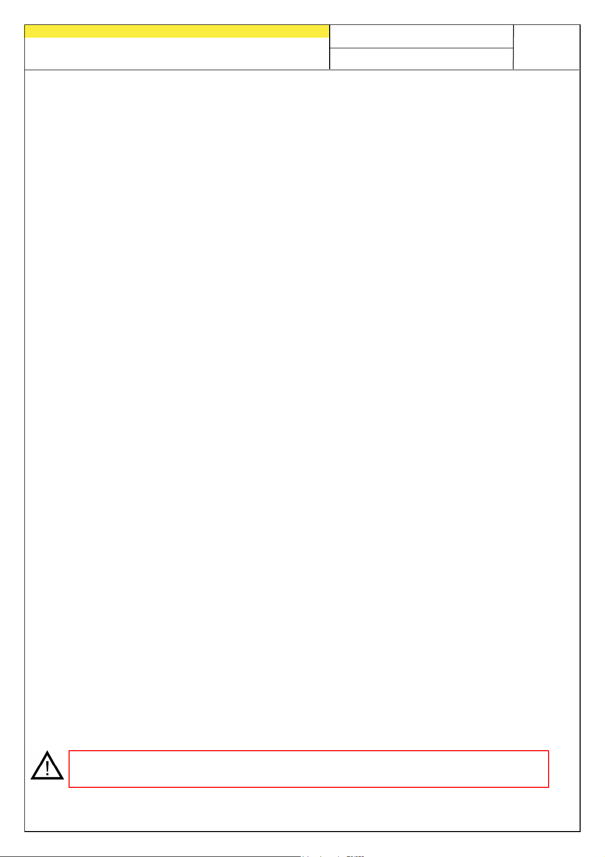
2.3 User interface of the control box
1
2
3
4
Fig.: 4
No. Meaning / use
1 Display LEDs: display error messages, software version and settings
2 Adjust the speed of the blower fan or spreading plate
3 Lights up when the control box is switched on
4
("on/off"): switches the implement on and off.
5 Lights up when the blower fan or the spreading plate is switched on.
6
: turns the blower fan or spreading plate on or off.
(Not possible with hydraulic fan!)
7
seeding shaft button, the seeding shaft starts rotating and the control lamp lights
up.
8 Lights up when the seeding shaft is switched on The LED flashes when 0 is set
as the speed on the rotary knob and the motor is switched on.
9 Adjust the speed of the seeding shaft
10 Lights up when there is no more seed in front of the fill level sensor.
5
turns the seeding shaft on or off. When pressing the
10
9
8
7
Page 7
Quality for Professionals
2.4 Starting up the implement
After switching on the implement with the on/off button, the control lamp above the
button lights up. This shows that the supply voltage is available.
As long as the on/off button is held, the software version is displayed. E01 =Software
1.1; E02= Software 1.2. This may be necessary in case of customer service.
You can now use the rotary knob on the left to adjust the speed of the blower fan /
spreading plate. The rotary knob on the right is used to adjust the speed of the
seeding shaft.
When you press the blower fan button, the fan motor (or the spreading plate on the
MDS) will start running.
As soon as you press the seeding shaft button, the seeding shaft starts rotating at
the set speed and you can start seeding.
7
2.5 Operation on the field
To begin sowing, press the seeding shaft button.
1st Stage: the LED control lamp beside the blower fan button flashes (the blower fan
motor or spreading plate is starting up).
2nd Stage: after a few seconds, the LED control lamp beside the blower fan button
lights up (blower fan motor is running).
3rd Stage: when the green LED control lamp beside the seeding shaft button lights
up, the gear motor that turns the seeding shaft and conveys the seed is switched on.
When you are turning at the headlands, you only have to press the seeding shaft
button so that the green LED control lamp is turned off. This stops the seeding shaft
and only the fan motor is still running.
When finishing work, press the on/off button on the control box to switch off the fan
motor and the seeding shaft. The LEDs are turned off and the control box is switched
off.
2.6 Calibration test
First determine the required speed for the seeding shaft based on the calibration
table (this can be found in the operating manual for the spreader).
The calibration test is started by pressing and holding the seeding shaft button for
3 seconds. The implement beeps once.
PLEASE NOTE: Always ensure that the blower fan is switched off before starting the
calibration test.
Page 8
8
Setting 1.2
"MDS" motor speed
"UD" motor spee
d
Quality for Professionals
After starting, the seeding shaft begins rotating without the fan motor for exactly one
minute.
The calibration test can be terminated at any time by pressing the seeding shaft
button or the on/off button on the control box.
If necessary, correct the seeding shaft speed and repeat the procedure.
TIP: refer to the respective operating manual of the seed drill to find out how to
prepare the seed drill for the calibration test.
2.7 Emptying the hopper
You can begin draining the hopper by pressing and holding the seeding shaft button
for 6 seconds when the seeding shaft is powered off. After 3 seconds, the calibration
test begins (1 short beep). By pressing and holding the button for an additional 3
seconds, the module switches to drain mode - the seeding shaft turns at full speed
(short beep 2 times)
You can stop a running function at any time by pressing the blower fan button or
on/off button.
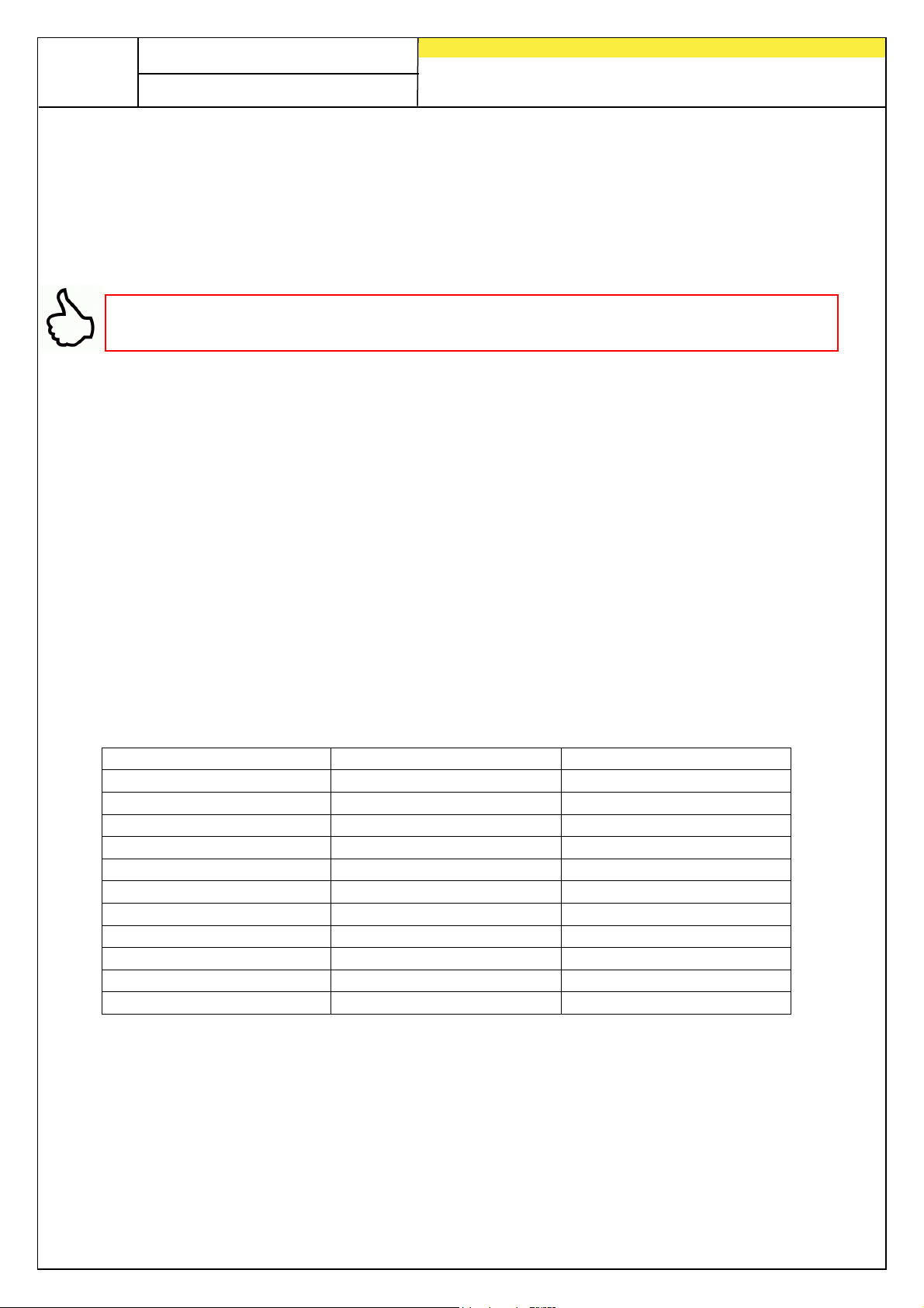
2.8 Spreading disc speed chart
This table shows you the spreading disc speed depending on your control box's
setting:
2
10
20
30
40
50
60
70
80
90
max.
100
300
600
900
1300
1600
1900
2250
2600
2800
3000
50
150
300
450
650
800
950
1100
1300
1400
1500
2.9 Automatic implement shut-off
When the control box is switched on and no button is pressed and the seeding shaft
is not switched on within 1.5 hours, the control box is switched off automatically.
Page 9
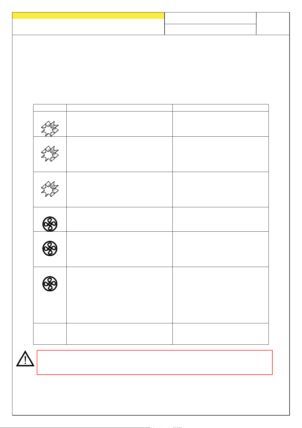
Display
Cause
Solutions
Quality for Professionals
3 Status messages and possible solutions
3.1 Controller messages
Error messages must be acknowledged with the on/off button and the spreader is
then switched off.
The following error messages can be displayed:
9
E01
E02
Indicates that the gear motor for the
seeding shaft is not connected.
Is displayed when the seeding shaft
cannot rotate or when the motor is
strained for too long at its limits.
E03
Is displayed when the motor
(seeding shaft) is connected and not
overloaded, but is still blocked.
E01
E02
E03
E04
CAUTION: If your battery is charged by a charger that is in "Start" operating mode,
there can be voltage peaks! These can cause damage to the electrical system of
the control box if it is also connected when the battery is being charged!
Indicates that the blower fan motor /
spreading plate motor is not
connected.
Indicates that the blower fan motor /
spreading plate motor cannot rotate
or that the blower fan motor /
spreading plate motor is being
strained for too long at its limits.
Is displayed when the motor (fan or
spreading plate) is connected and
not overloaded, but still does not
rotate.
For hydraulic fan with pressure
switch or pressure sensor: the fan is
not running or is not sending a signal
to the pressure switch/speed sensor.
Is displayed when the operating
voltage is too low.
Check the cables and plugs for
faults or damage.
Turn off the implement and check
if solid substances or similar
prevent the seeding shaft or
agitator from turning or impede
their operation.
Check if there is something
blocking the seeding shaft. If this
is not the cause of the problem,
please contact Customer
Service.
Check the programming (see
Point 7) and the cabling or plug.
Turn off the implement and check
if objects are blocking the blower
fan / spreading plate or impeding
their operation.
For hydraulic fan: Switch on the
hydraulic fan.
Please contact customer service.
Reduce the consumers, check
battery; check cabling, check
alternator
Page 10
10
•
•
Quality for Professionals
3.2 Assistance in the event of problems
Problems: Possible remedy:
No display after pressing
the on/off button.
Hydraulic fan is running,
E03 is still lit.
Check whether the power cable is properly inserted
into the control box and is also connected to the
correct terminals on the battery.
• CAUTION: Faulty connection or removal of the
flying fuse on the positive terminal of the power
cable can result in damage to the control box!
Is there no pressure switch installed? Programming,
see point 7.
4 Cleaning
Use a dry cloth to clean the control box.
Do not use any aggressive solvent! This may damage the implement.
5 Decommissioning, storage and disposal
5.1 Decommissioning the implement
Switch off the control box using the on/off button. Disconnect the control box from the
power supply after use.
5.2 Storage
The control box must be stored in a dry location protected from weather conditions.
5.3 Disposal
Disposal of the implement must be performed according to the local disposal
regulations for machines.
Page 11
Quality for Professionals
6 Accessories
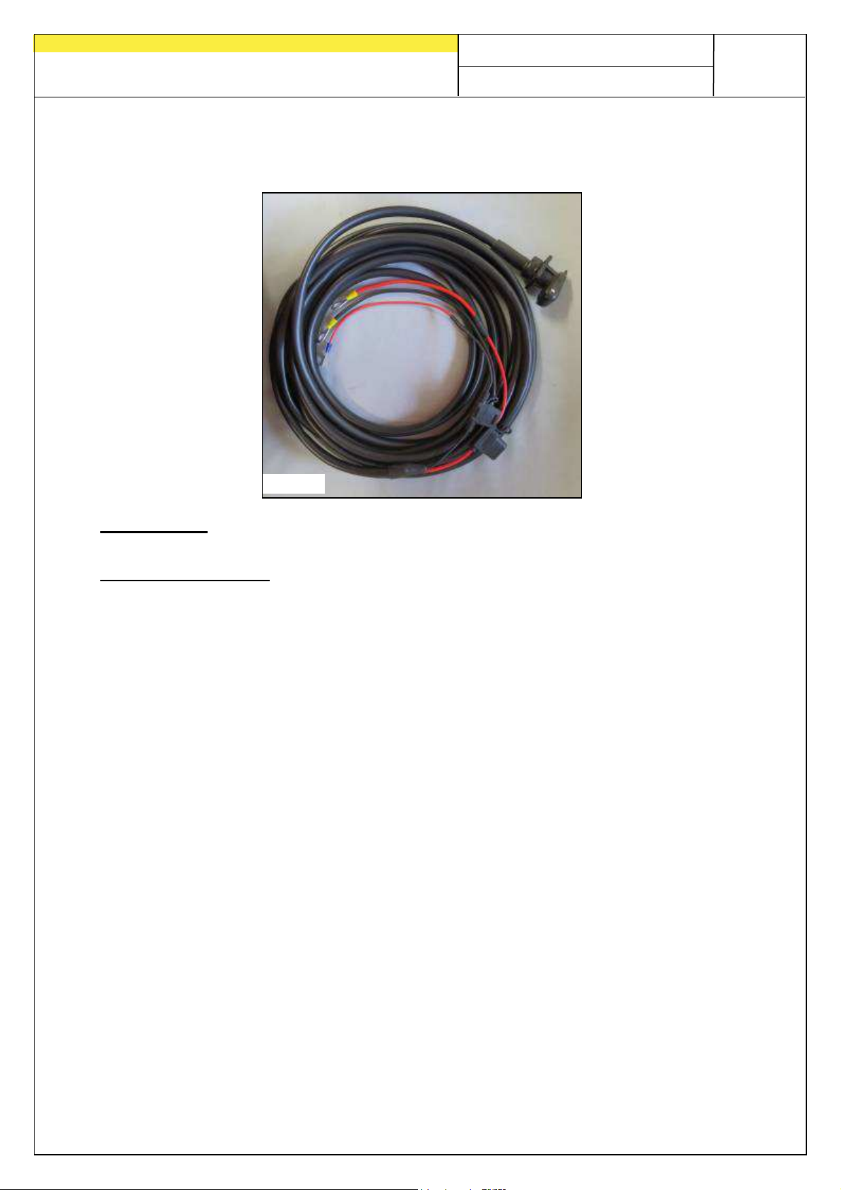
6.1 Tractor cable set (Item no.: 00410-2-022)
Cable length: 8 m
Fig.: 5
11
Connection diagram: Red (6 mm² cable) = 12 Volt
Red (1.5 mm² cable) = Ignition plus
Black (6 mm² cable) = Ground
For the power supply to the control box, without a standard 3-pin standard socket
on the tractor, a retrofit kit is available as an accessory.
The cable is 8 m long.
It is screwed directly on the terminals of the battery on the battery side, and at the
other end, a 3-pin standard socket is installed.
Page 12
12
Quality for Professionals
7 Programming menu
7.1 Blower fan / spreading plate
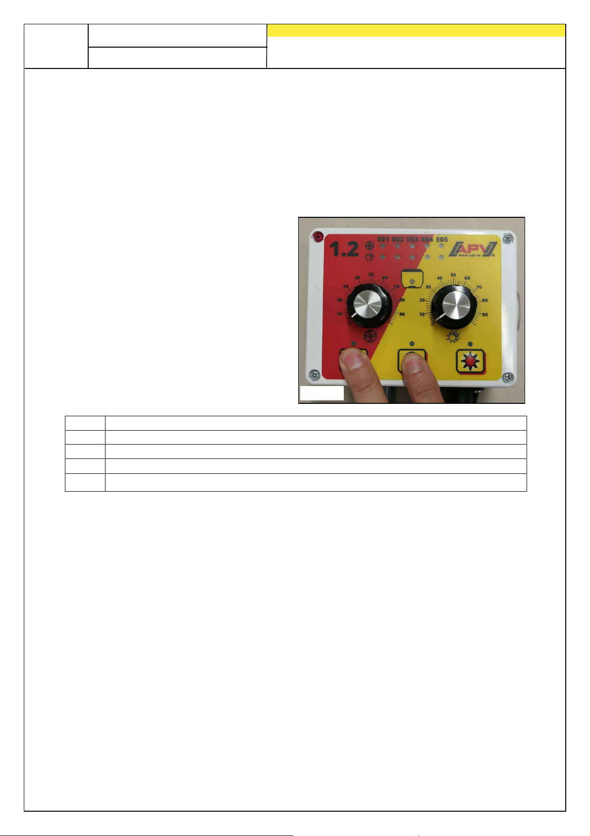
In this menu, you can configure if a hydraulic or PTO shaft-powered fan is set up in
lieu of an electric fan or if an MDG or MDS spreader is being operated.
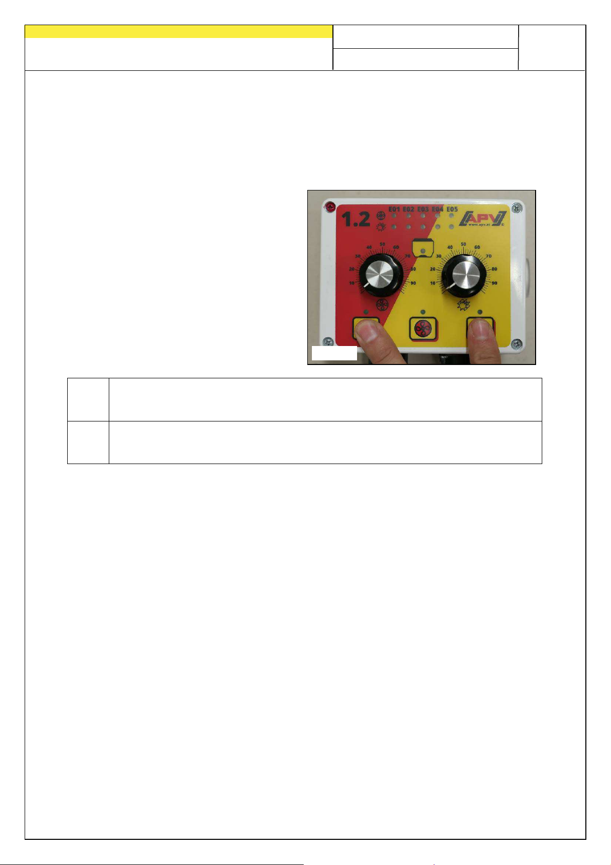
Perform the following actions to open the programming menu for the blower fan /
spreading plate:
Press and hold the on/off button
and briefly press the blower fan
button at the same time (see
Fig.: 6).
When pressing the blower fan
button repeatedly, the menu points
switch from E01 through E05.
By pressing the on/off button or the
seeding shaft button, the selection
is confirmed.
E01 Electric fan (standard configuration)
E02 Hydraulic fan with pressure switch
E03 Spreading plate (MDS/UD)
E04 Hydraulic fan with fan speed sensor (monitoring function - no display / control)
E05 Hydraulic fan without pressure switch (OFF) or no fan (MDG)
Fig.: 6
Page 13
Quality for Professionals
7.2 Seeding shaft motor
In this menu, you can specify the type of motor that is installed in the spreader.
Perform the following actions to open the programming menu for the blower fan /
spreading plate:
Press and hold the on/off button
and briefly press the seeding shaft
button at the same time (see
Fig.: 7).
Repeatedly pressing the seeding
shaft button switches between
settings E01 (P8 gear motor) or
E02 (P17 gear motor).
E01: P8 gear motor (standard setting)
for pneumatic seed drills PS 120-500
for multi-metering systems (MDG, MDP, MDS, MDC)
E02: P17 gear motor:
for pneumatic seed drills PS800, PS1200 and PS1600
for universal metering unit series (UD)
The setting is saved using the on/off button or the blower fan button.
Fig.: 7
13
Page 14
14
Quality for Professionals
Notes
Page 15
Quality for Professionals
Notes
15
Page 16

Quality for Professionals
Inspired by Farmers & realized by Professionals
APV - Technische Produkte GmbH
HEADQUARTERS
Dallein 15
AT - 3753 Hötzelsdorf
Tel.: +43 (0)2913 8001
Fax: +43 (0)2913 8002
www.apv.at
 Loading...