

Page 1

Series AK M80/86
Crossover Manifold
INSTALLATION AND OPERATION
MANUAL
Part Number 00-15000010
Revision 3
Copyright © July 2006
Advanced Pressure Technology (“AP Tech”)
687 Technology Way
Napa, CA 94558
Phone: (707) 259-0102
FAX: (707) 259-0117
Page 2

AK M80/86 Manual P/N 00-15000010 Rev 3
TABLE OF CONTENTS
1. DESCRIPTION.....................................................................................................................................3
2. SAFETY ...............................................................................................................................................4
2.1. General Safety Information.......................................................................................................4
2.2. AK M80/86 Crossover Manifold Specific Safety Information.................................................4
3. TECHNICAL SPECIFICATIONS .......................................................................................................5
3.1. AK M80/86 Specifications........................................................................................................5
3.2. AK M80/86 Facility Requirements...........................................................................................5
4. INSTALLATION .................................................................................................................................6
4.1. General......................................................................................................................................6
4.2. AK M80/86 Installation............................................................................................................6
4.3. Connect Gas Lines to AK M80/86............................................................................................7
4.4. Relief Valve Installation ...........................................................................................................8
4.5. Purge and Vent Equipment.......................................................................................................9
4.6. Initial Leak Test........................................................................................................................9
5. OPERATION......................................................................................................................................10
5.1. AK M80/86 Operation............................................................................................................10
6. TROUBLESHOOTING......................................................................................................................13
6.1. External leak ...........................................................................................................................13
6.2. Relief valve is opening and venting gas..................................................................................13
6.3. High delivery line pressure.....................................................................................................13
6.4. Low delivery line outlet pressure............................................................................................14
6.5. Both cylinders empty simultaneously.....................................................................................14
Page 2 of 14
Page 3
AK M80/86 Manual P/N 00-15000010 Rev 3
1. DESCRIPTION
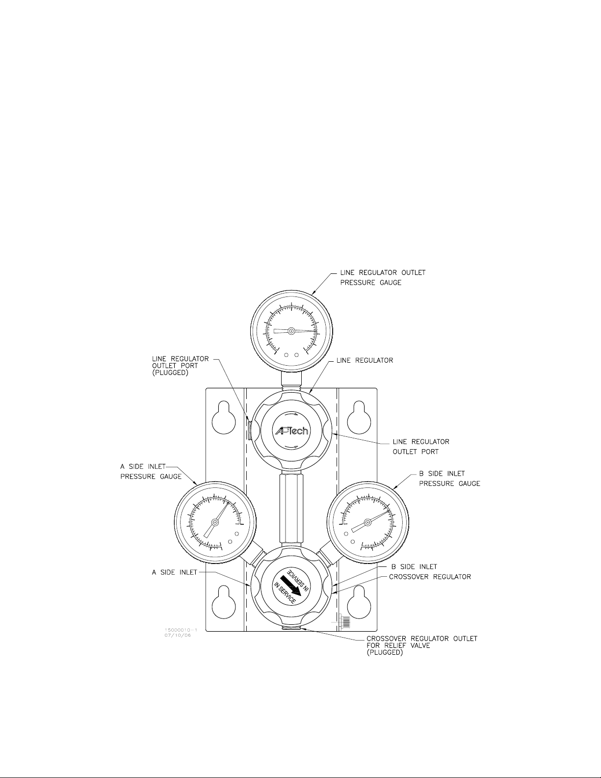
This installation and operation manual covers the series AK M80/86 crossover manifold. The AK M80/86
crossover manifold is used to maintain a continuous supply of source gas when the “in use” gas cylinder
is depleted by automatically drawing gas from a standby cylinder. The AK M80/86 consists of a
crossover regulator and a line regulator mounted to a common panel. The crossover regulator consists of
two regulators with separate inlets and a common outlet, machined into a single body. Two pressure
gauges are installed in the crossover regulator to indicate the inlet pressure from the A Side and B Side gas
cylinders. The crossover regulator supplies the line regulator. The crossover regulator has a plugged outlet
port at the 6:00 o’clock position for installation of a relief valve. A relief valve is recommended to protect
the low pressure side of the crossover regulator from full cylinder pressure in the event of a seat failure.
The line regulator has one primary outlet port, a secondary plugged outlet port, and a pressure gauge that
indicates outlet pressure. Custom configurations may vary slightly from this standard design.
shows the basic design.
Figure 1
C
R
N
.
I
D
.
E
R
C
Figure 1. AK M80/86 Crossover Manifold Front View
Page 3 of 14
Page 4

AK M80/86 Manual P/N 00-15000010 Rev 3
2. SAFETY
The user is strongly recommended to carefully read this section covering general safety information
and to adhere to specific safety information located throughout this manual.
2.1. General Safety Information
All technicians that install, operate, or maintain this equipment should be trained in the use and hazards of
compressed gases. Technicians should also be familiar with the hazards associated with the particular gas
being delivered. These hazards can include high pressure, asphyxiation, toxicity, flammability,
corrosivity, etc. Material safety data sheets are available from gas suppliers that provide detailed
information on the hazards associated with a particular gas.
Appropriate personnel protective equipment should be worn at all times as recommended by the material
safety data sheet for the particular gas and as required by safety practices at the installation site. This
equipment may include safety glasses, safety shield, rubber gloves, aprons, etc.
Never exceed the maximum working pressure of the equipment.
Equipment shall be installed in a manner that meets local, state, and federal regulations and safety
guidelines. General guidelines for compressed gases can be obtained from the Compressed Gas
Association (
Prior to disassembling manifold lines, the system may need to be purged using nitrogen or another gas to
remove any hazardous gases. The AK M80/86 system does not have built-in purging capability, which is
the responsibility of the user.
http://www.cganet.com/) and the European Industrial Gases Association (www.eiga.org).
2.2. AK M80/86 Crossover Manifold Specific Safety Information
An overpressure relief device should be installed in the plugged low-pressure (6:00 o’clock) port of the
crossover regulator. The outlet of the relief device should be connected to a scrubber system or directed
away from personnel as appropriate.
The AK M80/86 manifold should be checked for leaks upon installation and inspected periodically during
use.
A shut off valve and check valve should be installed between the both supply cylinders and the AK
M80/86 manifold inlet connections to prevent gas from the cylinder in use from escaping when a cylinder
is being replaced.
Installation of purge and vent valves are recommended when used with hazardous gases and exposure to
the gas can result in a safety hazard to personnel. Purge equipment is the responsibility of the user.
Page 4 of 14
Page 5

AK M80/86 Manual P/N 00-15000010 Rev 3
3. TECHNICAL SPECIFICATIONS
3.1. AK M80/86 Specifications
3.1.1. Physical
Dimensions are approximately 6 inch wide by 10 inch high by 8-1/2 inch deep
Weight is approximately 9 lbs.
Mounting is by 4 each 1/4 inch diameter screws
3.1.2. Pressure and Flow
3500 psig maximum inlet pressure
250, 150, 100, 60, or 30 psig maximum outlet pressure options (specified when ordered)
75 slm nitrogen maximum flow at 200 psig minimum inlet pressure (depending on line regulator
outlet pressure setting)
3.2. AK M80/86 Facility Requirements
The following is needed to install the AK M80/86 manifold at the users facility.
Horizontal strut channel or wall with anchor bolts
1/4 inch diameter, hex head type screws (1/4-20 or 1/4-28 thread acceptable)
The following is required for proper operation of the equipment:
Check valve for installation between cylinder and regulator inlet port
Manual valve for installation between cylinder and check valve
Appropriate purge and vent system for hazardous gases
Relief valve for installation on crossover regulator low pressure port
Relief valve for installation on line regulator low pressure port
Page 5 of 14
Page 6

AK M80/86 Manual P/N 00-15000010 Rev 3
4. INSTALLATION
This section describes how to install the equipment at a user facility.
4.1. General
Use Teflon® pipe thread tape on NPT connections. When mating a 316 stainless steel pipe fitting to a 316
stainless steel AK M80/86 body, it is recommended that Teflon tape be applied to the first NPT thread to
prevent galling upon assembly. For brass fittings, do not apply thread tape to the first NPT thread to
reduce the chance of introducing pieces of thread tape into the system. Use care not to apply Teflon tape
such that loose tape will come free and enter the flow path.
Do not drop or jar the switchover manifold because damage to internal parts and pressure gauges may
result.
Inspect the manifold after unpacking and before installation. If any damage is observed, contact factory
for repair.
4.2. AK M80/86 Installation
Select a location for the manifold that is sheltered from the environment and away from sources of heat or
sparks. The area should be protected from vehicles and moving mechanical equipment. The area must be
accessible for ease of cylinder replacement.
It is recommended that the screw head maximum size be 5/8 inch diameter so that the mounting panel
large holes can easily slip over the screw head. Two possible methods to mount the manifold are given
below.
Install two metal framing channels (i.e. Unistrut® type or equivalent) horizontally on the wall and
parallel to each other. Space the channels 5-1/4 inches apart on center. Secure the AK M80/86
manifold to the channel using 1/4 inch screws.
Install anchors in the wall using the pattern shown on
against a wall and mark the location of the mounting holes. Mount the AK M80/86 manifold
directly to the wall and secure with 1/4 inch diameter screws.
Figure 2 or hold the AK M80/86 manifold
Page 6 of 14
Page 7

AK M80/86 Manual P/N 00-15000010 Rev 3
C
R
N
.
I
D
.
E
R
C
Figure 2. AK M80/86 Crossover Manifold Mounting Hole Pattern
4.3. Connect Gas Lines to AK M80/86
Position a gas cylinder on each side of the AK M80/86 panel. Secure cylinders in place using an
appropriate restraint system.
Equipment can be supplied with various types of fittings and connections. The standard connections are
1/4 inch female NPT. Inspect the system to determine if the connection is NPT, tube compression, or
other.
Install a check valve into port labeled “HP-A” on AK M80/86 manifold. Flow arrow on check valve
should be pointing into the AK M80/86 manifold inlet port. Install manual shut off valve onto check
valve.
Page 7 of 14
Page 8

AK M80/86 Manual P/N 00-15000010 Rev 3
Install a check valve into port labeled “HP-B” on AK M80/86 manifold. Flow arrow on check valve
should be pointing into the AK M80/86 manifold inlet port. Install manual shut off valve onto check
valve.
Connect a “pigtail” (bent piece of tubing with loops for flexibility and to reduce stress on connections) or
flexible braided hose from the outlet of the left cylinder valve to the manual valve on the AK M80/86
manifold regulator inlet port labeled “HP-A”.
Connect a “pigtail” (bent piece of tubing with loops for flexibility and to reduce stress on connections) or
flexible braided hose from the outlet of the right cylinder valve to the manual valve on the AK M80/86
manifold regulator inlet port labeled “HP-B”.
Install appropriate fitting into line regulator 1/4 NPT female outlet port. Install delivery line to point of
use using tubing or piping.
4.4. Relief Valve Installation
Remove 1/4 NPT plug from port on AK M80/86 crossover regulator. Clean Teflon thread tape from port.
Install a relief valve that is set above the AK M80/86 crossover regulator pressure settings. See
for recommended nominal relief valve set pressures. If necessary due to gas properties, route the relief
valve outlet line to an appropriate scrubber or exhaust system. Otherwise, direct the relief valve outlet
away from personnel.
Table 1
AK M80/86 Model
AK M8002, M8602 85-115 psig 150 psig
AK M8006, M8606 85-115 psig 150 psig
AK M8010, M8610 135-165 psig 200 psig
AK M8015, M8615 225-275 psig 325 psig
AK M8025 435-515 psig 600 psig
Table 1. Crossover Relief Valve Nominal Set Pressures
It is also suggested that a relief valve be installed in the plugged outlet port of the AK M80/86 line
regulator. Remove 1/4 NPT plug from outlet port on AK M80/86 line regulator. Clean Teflon thread tape
from port. Install a relief valve that is set above the AK M80/86 line regulator maximum outlet pressure.
See
Table 2 for recommended nominal relief valve set pressures. If necessary due to gas properties, route
the relief valve outlet line to an appropriate scrubber or exhaust system. Otherwise, direct the relief valve
outlet away from personnel.
Nominal Crossover
Regulator Outlet Range
Relief Valve
Set Pressure
Page 8 of 14
Page 9

AK M80/86 Manual P/N 00-15000010 Rev 3
AK M80/86 Model
AK M8002, M8602 30 psig 50 psig
AK M8006, M8606 60 psig 100 psig
AK M8010, M8610 100 psig 150 psig
AK M8015, M8615 150 psig 200 psig
AK M8025 250 psig 300 psig
Table 2. Line Regulator Relief Valve Nominal Set Pressures
Line Regulator
Maximum Outlet
Relief Valve
Set Pressure
4.5. Purge and Vent Equipment
If required due to gas properties (such as for hazardous gases), install purge and vent valves to enable the
operator to remove hazardous gases from the lines using an inert purge gas before connecting and
disconnecting gas cylinders.
4.6. Initial Leak Test
Connect a nitrogen (or other appropriate gas) cylinder with a pressure regulator to both inlets on the
AK M80/86 manifold. Regulate the pressure to less than the manifold maximum inlet pressure and no
more than 90% of the inlet gauge maximum range.
Pressurize the manifold with nitrogen. Increase the line regulator to the maximum outlet.
Check all lines for leaks by listening for audible leakage and applying soap solution to NPT connections.
Disassemble, repair, and retest all leaks.
Disconnect the nitrogen cylinder.
Fully close (turn knob counterclockwise) the AK M80/86 line regulator.
Page 9 of 14
Page 10

AK M80/86 Manual P/N 00-15000010 Rev 3
5. OPERATION
This section describes operation of the AK M80/86 crossover manifold.
Figure 3. AK M80/86 Installation Schematic
5.1. AK M80/86 Operation
5.1.1. General Principle of Operation
The knob for the crossover regulator has an “IN SERVICE” label with an arrow. When the knob is turned
so that the arrow points toward the B Side (right) cylinder (approximately the 4:30 o’clock position with
the line regulator at 12:00 o’clock position), then the B Side (right) cylinder is the primary gas supply and
the A Side (left) cylinder is the standby gas supply. When the knob is turned so that the arrow points
toward the A Side (left) cylinder (approximately the 7:30 o’clock position), then the A Side (left) cylinder
is the primary gas supply and the B Side (right) cylinder is the standby gas supply.
The crossover regulator is comprised of a fixed outlet pressure regulator and an adjustable (limited range)
outlet pressure regulator. The A Side (left) cylinder supplies the fixed outlet pressure regulator. The B Side
(right) cylinder supplies the adjustable outlet pressure regulator. The adjustable outlet pressure regulator
has the “side selection outlet” knob with the “IN SERVICE” label and arrow. This regulator can be
rotated only 270 degrees to adjust the B Side outlet pressure slightly above or slightly below the A Side
fixed outlet pressure. It is this slight change in B Side outlet pressure that selects which cylinder is
supplying gas and which cylinder is on standby. When the cylinder supplying gas is empty, then it is time
to replace that cylinder using the protocol in Section
5.1.3 or 5.1.4 as appropriate.
Page 10 of 14
Page 11

AK M80/86 Manual P/N 00-15000010 Rev 3
The line regulator is used to maintain a constant delivery pressure since the outlet pressure from the
upstream crossover regulator fluctuates as A Side and B Side cylinders empty and are replaced. The line
regulator is fully adjustable to the maximum outlet pressure. Rotating the knob clockwise increases the
line regulator outlet pressure.
5.1.2. Initial Pressurization
Confirm that an initial leak test has been performed and all leaks repaired.
Close all system valves.
Close line regulator by turning knob counterclockwise.
Turn side selection knob on AK M80/86 crossover regulator clockwise until internal stop is contacted.
The “IN SERVICE” label arrow on the knob should be pointing toward the B Side (right) cylinder
(approximately the 4:30 o’clock position).
Open B Side cylinder valve and manual valve between B Side (right) cylinder and AK M80/86 crossover
manifold. Pressure on B Side (right) gauge should indicate the cylinder pressure.
Open A Side cylinder valve and manual valve between A Side (left) cylinder and AK M80/86 crossover
manifold. Pressure on A Side (left) gauge should indicate the cylinder pressure.
Adjust line regulator (clockwise) to desired delivery pressure setting as indicated on pressure gauge.
Check all system connections for leaks. This can be done with soap solution on each connection, by
listening for an audible hissing sound, or by using an appropriate gas detector.
5.1.3. B Side (right) Cylinder Depleted
Confirm that B Side (right) side cylinder is depleted by reading the pressure gauge. The exact pressure
will depend on the specific AK M80/86 model. The approximate pressure when the B Side cylinder is
depleted is given in
Rotate AK M80/86 crossover manifold “selection” knob counterclockwise until internal stop is contacted.
The knob will rotate approximately 270 degrees. The “IN SERVICE” label arrow on the knob should be
pointing toward the A Side (left) cylinder (approximately the 7:30 o’clock position).
Close B Side (right) cylinder valve and manual valve between B Side (right) cylinder and AK M80/86
crossover manifold. If required, operate equipment to purge line from cylinder to manifold.
Disconnect depleted B Side cylinder and connect full cylinder.
Open B Side (right) cylinder valve and manual valve between B Side (right) cylinder and AK M80/86
crossover manifold. Pressure on B Side (right) gauge should indicate the cylinder pressure.
Table 3.
AK M80/86 Model
AK M8002, M8602 100
AK M8006, M8606 100
AK M8010, M8610 150
B Side Depletion
Pressure, psig
AK M8015, M8615 250
AK M8025 475
Table 3. Approximate B Side Cylinder Depletion Pressure
Page 11 of 14
Page 12

AK M80/86 Manual P/N 00-15000010 Rev 3
5.1.4. Cylinder “A” Depleted
Confirm that A Side (left) side cylinder is depleted by reading the pressure gauge. The exact pressure will
depend on the specific AK M80/86 model. The approximate pressure when the A Side cylinder is depleted
is given in
Rotate AK M80/86 crossover manifold “selection” knob clockwise until internal stop is contacted. The
knob will rotate approximately 270 degrees. The “IN SERVICE” label arrow on the knob should be
pointing at approximately 4:30 o’clock position toward the B Side (right) cylinder.
Close A Side (left) cylinder valve and manual valve between A Side (left) cylinder and AK M80/86
crossover manifold. If required, operate equipment to purge line from cylinder to manifold.
Disconnect depleted A Side cylinder and connect full cylinder.
Open A Side (left) cylinder valve and manual valve between A Side (left) cylinder and AK M80/86
crossover manifold. Pressure on A Side (left) gauge should indicate the cylinder pressure.
Table 4.
AK M80/86 Model A Side Depletion
Pressure, psig
AK M8002, M8602 85
AK M8006, M8606 85
AK M8010, M8610 135
AK M8015, M8615 225
AK M8025 435
Table 4. Approximate A Side Cylinder Depletion Pressure
Page 12 of 14
Page 13

AK M80/86 Manual P/N 00-15000010 Rev 3
6. TROUBLESHOOTING
The most common problem conditions and possible causes/corrections are described below. Please
contact the factory for assistance with other problem conditions or to discuss a specific problem in more
detail.
6.1. External leak
Possible causes:
Connection not assembled properly with Teflon tape.
Connection not tightened properly.
Correction:
Inspect equipment to determine source of the leak. Repair leak by disassembling the connection,
inspecting parts, and reassembling using good shop practice.
If the leak is from the bonnet of the regulator, then AP Tech recommends that the AK M80/86
manifold be sent back to the factory for repair (however, a field repair kit is available).
6.2. Relief valve is opening and venting gas
Possible causes:
Relief valve opens below set pressure.
Seat leak on AK M80/86 crossover regulator causing an overpressure condition.
Correction:
Remove and bench-test relief valve. Replace relief valve if defective.
If relief valve operates correctly, then temporarily install a pressure gauge in relief valve port of AK
M80/86 manifold and monitor pressure. A continuous pressure rise after initial pressurization
indicates a seat leak on the AK M80/86 crossover regulator. If the problem is a seat leak, then AP
Tech recommends that the AK M80/86 manifold be sent back to the factory for repair (however, a
field repair kit is available).
6.3. High delivery line pressure
Possible causes:
Other gas source from point of use is pressurizing delivery line.
Seat leak or high creep on line regulator.
Regulator knob adjusted incorrectly.
Correction:
Check to see if a different gas source can be pressurizing the line.
If another gas source is not the cause of the high delivery line pressure, then shut off the supply to the
point of use, close the line regulator, vent the delivery line, and readjust to desired outlet pressure. If
the line outlet pressure continues to rise above the set pressure, then it is likely the line regulator has a
seat leak and AP Tech recommends that the AK M80/86 manifold be sent back to the factory for
repair (however, a field repair kit is available). If the outlet pressure does not change significantly,
then it is likely the regulator was adjusted incorrectly.
Page 13 of 14
Page 14

AK M80/86 Manual P/N 00-15000010 Rev 3
6.4. Low delivery line outlet pressure
Possible causes:
Flow restriction.
High flow at point of use
Regulator knob adjusted incorrectly.
Correction:
Shut off the supply to the point of use and see if the line outlet pressure returns to normal setting. If
outlet pressure returns to normal, then high flow or a flow restriction is the likely cause. Check the
flow requirement at the point of use.
If line outlet pressure is still low, readjust the line regulator knob to desired pressure. If line outlet
pressure returns to normal, then it is likely that the regulator was adjusted incorrectly.
6.5. Both cylinders empty simultaneously
Possible causes:
External leak on high pressure connection from standby cylinder to AK M80/86 crossover manifold.
Vent valve leaking past seat (if installed).
High flow at point of use.
Seat leak on crossover regulator supplied by standby gas cylinder.
Correction:
Check for external leaks especially on the high pressure line from the standby cylinder to the
AK M80/86 crossover manifold.
If there is a vent valve on the line from the gas cylinder to the AK M80/86 crossover manifold, check
to see if the vent valve is leaking across the seat.
Verify the flow demand is below the manifold rating. In general, high flow will empty the “IN
SERVICE” cylinder faster than the standby gas cylinder.
Momentarily shut off the cylinder valve on the standby gas cylinder. If the pressure on the standby
gas cylinder pressure gauge drops, then high flow demand or a seat leak on the regulator supplied by
the standby gas cylinder is the probably cause.
Page 14 of 14
 Loading...