

Page 1
Zone Control System
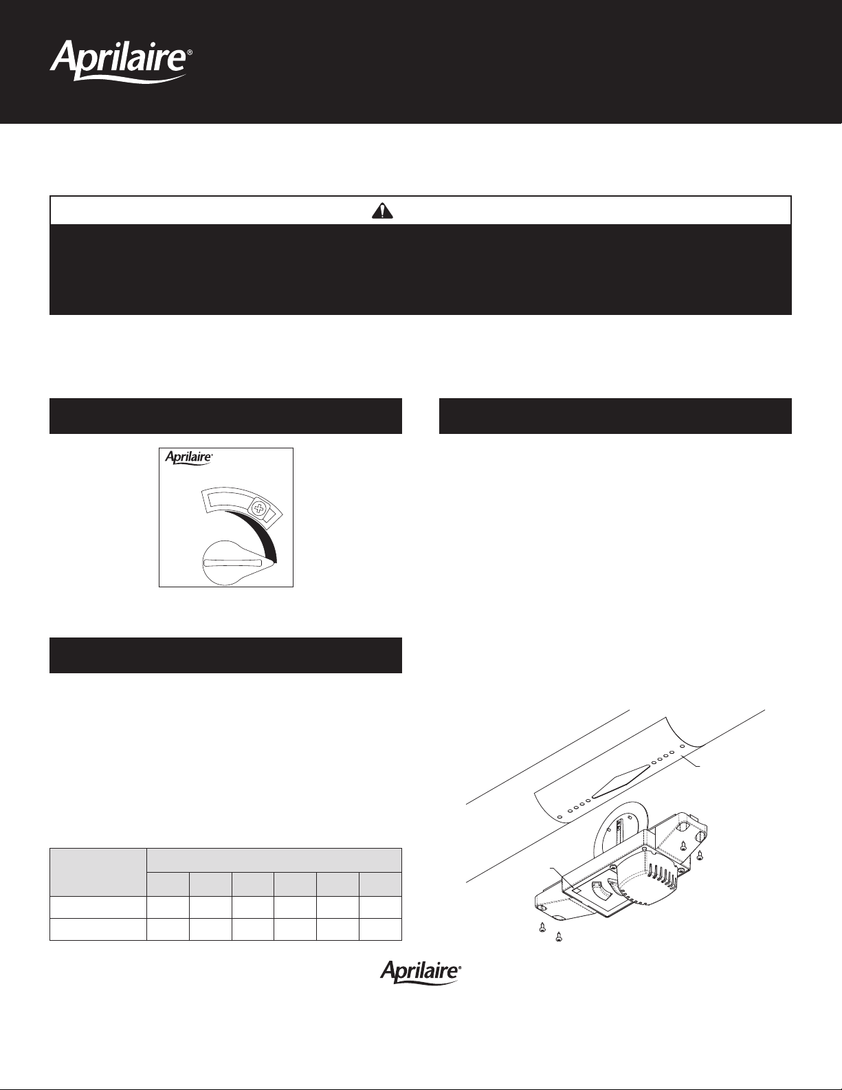
DO NOT
INSULATE
ACTUATOR
TEMPLATE
DAMPER
LABEL
Zone Control System
CLOSED
OPEN
B
Y
P
A
S
S
Existing Home Damper Installation Instructions
CAUTION
1. Sharp edges may cause serious injury from cuts. Use care when cutting openings and handling duct work.
2. A zone control system may not control temperature properly unless the HVAC system is correctly sized and balanced.
3. Install dampers in supply ducts only, and as close to the heating and cooling equipment as possible.
The position of the damper blade, as supplied, is in the open position. The damper is power-closed/spring-opened, and must be wired
to the zone control panel damper terminals that supply the required 12 VA at 24 VAC. (See zone control panel installation instructions
for specific wiring details.)
APRILAIRE RECTANGULAR DAMPER INSTALLATION PROCEDURE
Step 1: Using the template provided, drill the holes for
appropriate duct size.
90-1679
Preset Adjustable Stop Position
ADJUSTABLE STOP
Each Aprilaire Damper has an adjustable stop screw whose
position determines the amount of rotation the damper blades
make when energized. The stop screw is factory preset to a
position that allows the correct amount of predetermined
bypass air to go through the damper. To adjust the factory
preset bypass setting loosen the stop screw, adjust accordingly
and tighten the screw in place. To completely close the blades,
loosen the stop screw and move it to the closed position.
Adjustable
Stop Position
Factory Setting 8 20 25 39 57 81
Fully Closed 777777
CFM @ Supply Side Pressure 0.2" w.c.
6704 6705 6706 6707 6708 6710
Step 2: Install the damper using four 1/2” long (min.) sheet
metal screws (field supplied).
Step 3: Use the wire labels provided to simplify identification
of the damper wiring. Label each damper with the
corresponding zone and a letter.
Step 4: Wire to Zone Control Panel (NO, COM) damper
terminals, or to a Model 8028 Damper Power
Distribution Panel.
NOTE: Support all duct work in accordance with local code
or SMACNA standards.
90-1680
10009425 9.11
B2205508A
P.O. Box 1467 • Madison, WI 53701-1467 • Phone: 800/334-6011 • Fax: 608/257-4357 • www.aprilairepartners.com
© 2011 Aprilaire – A division of Research Products Corporation
Printed in U.S.A.
 Loading...