

Page 1
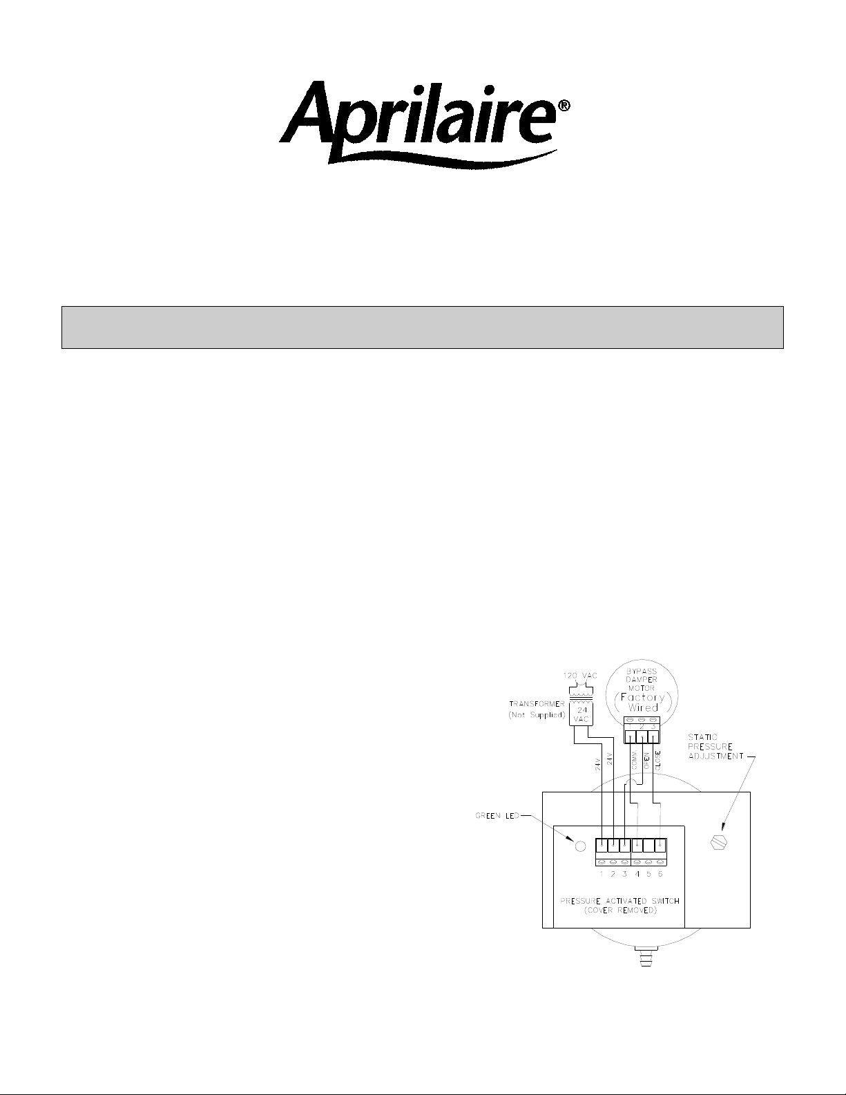
Figure1
ZONED COMFORT CONTROL SYSTEM
MODEL 6208, 6210, 6212, 6214, 6216, 6218 and 6220
MOTORIZED STATIC PRESSURE CONTROLLED BYPASS DAMPER
INSTALLATION INSTRUCTIONS
CAUTION: Sharp edges may cause serious injury from cuts.
Use care when cutting and handling ductwork.
PARTS PROVIDED:
Motorized Static Pressure Controlled Bypass Damper
Pressure Sensing Probe
3’ Clear Tubing (1/4” I.D., 3/8” O.D.)
POWER REQUIREMENT:
24 VAC Transformer, 3VA per bypass damper
1. IDENTIFY BYPASS DAMPER POSITION IN SYSTEM
Identify where the bypass damper is to be installed. The bypass damper must be located downstream
of any heating or cooling components and upstream of all zone dampers.
The bypass damper should be installed with the bypass air being discharged into the return air plenum
(up to 30% of total system airflow), above the ceiling if this area is used as a common return or into a
dump zone.
2. INSTALL THE DAMPER TO THE DUCTWORK
Install the damper with crimped end downstream.
The bypass damper must be installed such that the
diaphragm of the static pressure control is in the
vertical position.
Secure the damper to the duct with ½” long, #8 or #10
sheet metal screws (not included).
Insulate the damper only (not controls).
3. INSTALL THE STATIC PRESSURE PROBE
The probe should then be inserted into the main supply
plenum, downstream of the bypass damper and at least 2
to 3 feet from the air handling unit in a straight section of
the duct at the center line. Attach one end of the sensing
tube to the static pressure control and the other end to
the pressure sensing probe.
4. PROVIDE POWER TO BYPASS DAMPER
Supply 24VAC to the bypass damper (refer to Figure 1 for
details).
Page 2
©Research Products Corporation 2006
61000080
B2203573B
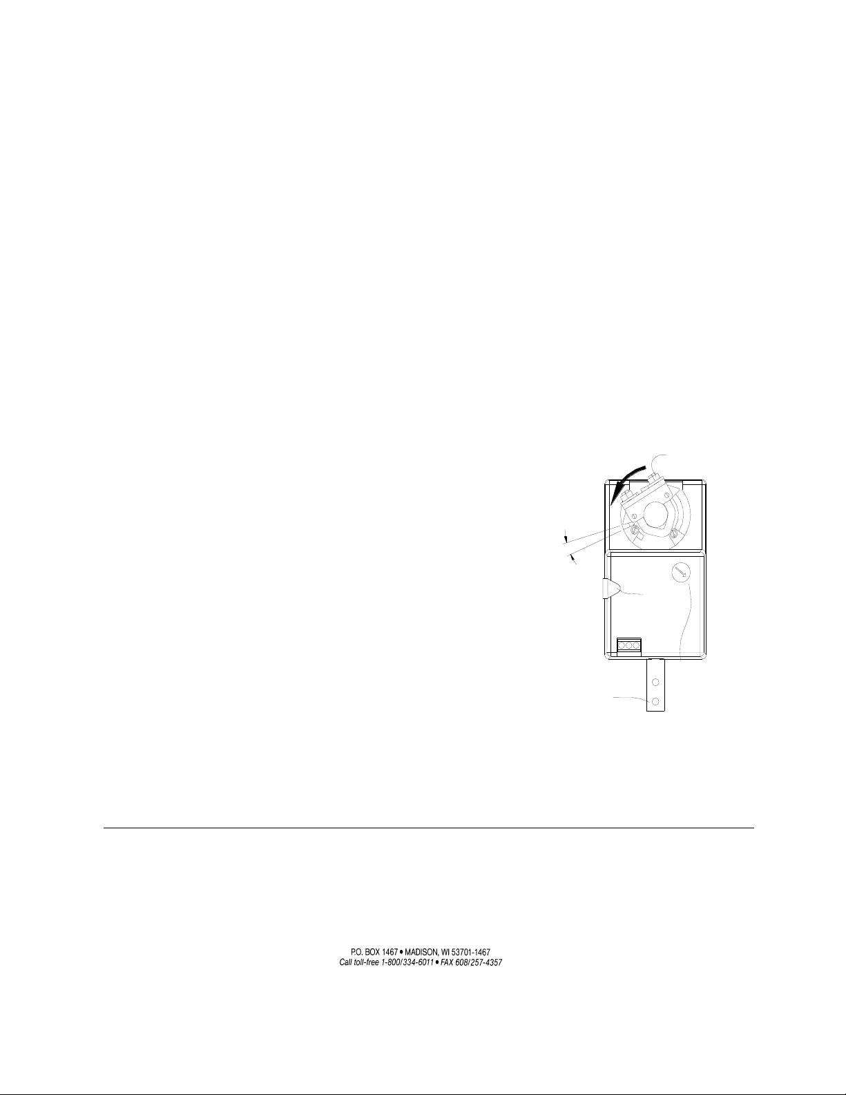
Figure 2
1/16" - 1/8"
UNIVERSAL
CLAMP
BRACKET
ANTI-ROTATION
OVERRIDE
MANUAL
BUTTON
0
1
VERIFY
"DIRECTION OF
ROTATION"
SWITCH IS SET
TO 1
5. ADJUSTING THE STATIC PRESSURE CONTROL
The bypass damper features a power open/power closed 24 volt actuator that is controlled by a static
pressure switch with integral time delay control. As the system pressure rises above the desired setting,
the damper will immediately open to relieve the pressure, causing the system pressure to return to the
desired setting. As the system pressure drops below the desired static pressure, the damper will delay
approximately 10 seconds and then begin to close until the static pressure in the system is returned to
the pre-set system pressure. Consult furnace/blower manufacturer recommendations for system
pressure/airflow.
Use the following guidelines to adjust the static pressure control:
A. Confirm that the HVAC system has been properly balanced.
B. Ensure all zone dampers are fully open and that the filter is clean (replace if necessary).
C. Turn on the system blower at high speed. You may need to make a cooling call to do this. If the
outside temperature is below 50°F, do not turn on the compressor. Disconnect power to the
condensing unit by switching off the circuit breaker or removing the fuse before making a cooling call.
D. With the air handler running and the bypass damper system powered, turn the static pressure
adjusting screw counterclockwise until the bypass damper just starts to open and the green LED
turns on. Then, turn the adjusting screw clockwise just enough so the green LED turns off and the
damper is fully closed. Refer to Figure 1 for location of adjustment screw and LED indicator.
E. If the damper is installed between the supply and return plenum, then the pressure drop across the
damper is approximately equal to the system pressure.1
ACTUATOR REPLACEMENT INSTRUCTIONS:
Use the following guidelines to replace the actuator:
1. Loosen the two nuts on the universal clamp with an 8mm
wrench. Remove the anti-rotation bracket and slide the
actuator off the damper shaft.
2. Turn the damper blade to its fully closed position.
3. With the manual override button depressed, rotate actuator
clamp counter clockwise to about 1/16”-1/8” between actuator
stop and clamp (See Figure 2). Slide actuator over shaft and
finger-tighten nuts.
4. Replace anti-rotation bracket. Secure bracket with self-tapping
screws. Tighten the two nuts on the universal clamp with 8 mm
wrench, 3-5ft-lb torque. (Actuator will compress damper blades
when reaching end position for an air-tight seal.)
1. Many factors influence the performance of the damper including inlet and outlet conditions. Your
application conditions are unlikely to match the test conditions exactly. These instructions are meant
as guidelines only.
 Loading...