

Page 1
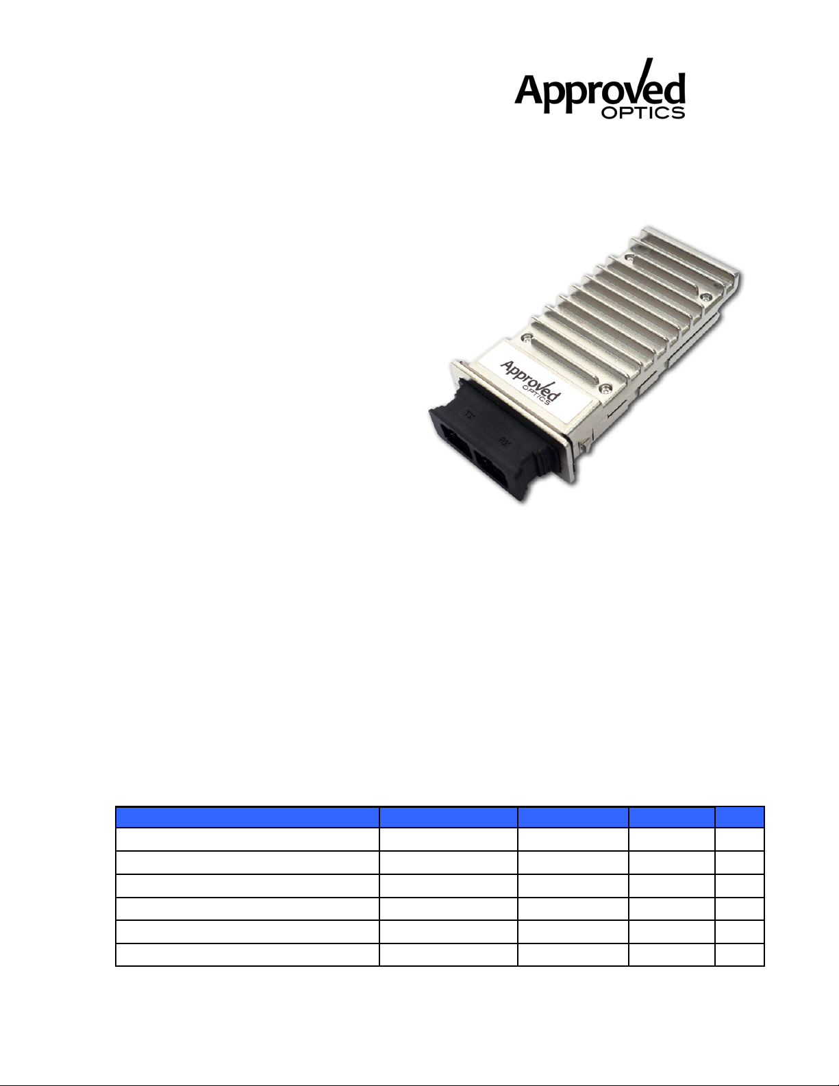
J8436A-A
X2-SR 10GB Module
850nm, 300m, MMF, SC RoHS6
_______________________________________________________
J8436A-A
10GBASE X2 Transceiver
Features
• Hot pluggable X2 MSA form factor
• Total power consumption: 2.2 W maximum
• RoHS-6 compliant (lead-free)
• Temperature range 0°C to 70°C
Transmission distance of 300m
•
Uncooled 850 nm VCSEL laser
•
SC connector, multimode fiber
•
Full duplex transmission mode
•
Digital Optics Monitoring (DOM)
•
Power supply: +5.0 V, +3.3 V
•
Adaptable Power Supply (APS: +1.2 V)
•
XAUI electrical interface
•
4x 3.125 Gb/s Ethernet
4x 3.1875 Gb/s Fibre Channel
• Management and control via MDIO 2-wire bus
• Separated signal/chassis ground
• Mid Pak module variance for front panel mounting
• De-latch mechanism with low extraction force
Absolute Maximum Ratings
Parameter Symbol Min Max Unit
Storage Ambient Temperature1) TS -40 85 °C
Operating Case Temperature1) TC 0 70 °C
Supply Voltage +5.0 V V5 0 6 V
Supply Voltage +3.3 V V3 0 4 V
Supply Voltage APS Vaps 0 1.5 V
Static Discharge Voltage, All Pins2) STd
500 V
Approved Optics, Inc. www.ApprovedOptics.com
Page 1 of 8
Page 2
J8436A-A
X2-SR 10GB Module
850nm, 300m, MMF, SC RoHS6
_______________________________________________________
Average Receive Optical Power RxP max
Exceeding any one of these values may permanently destroy the device.
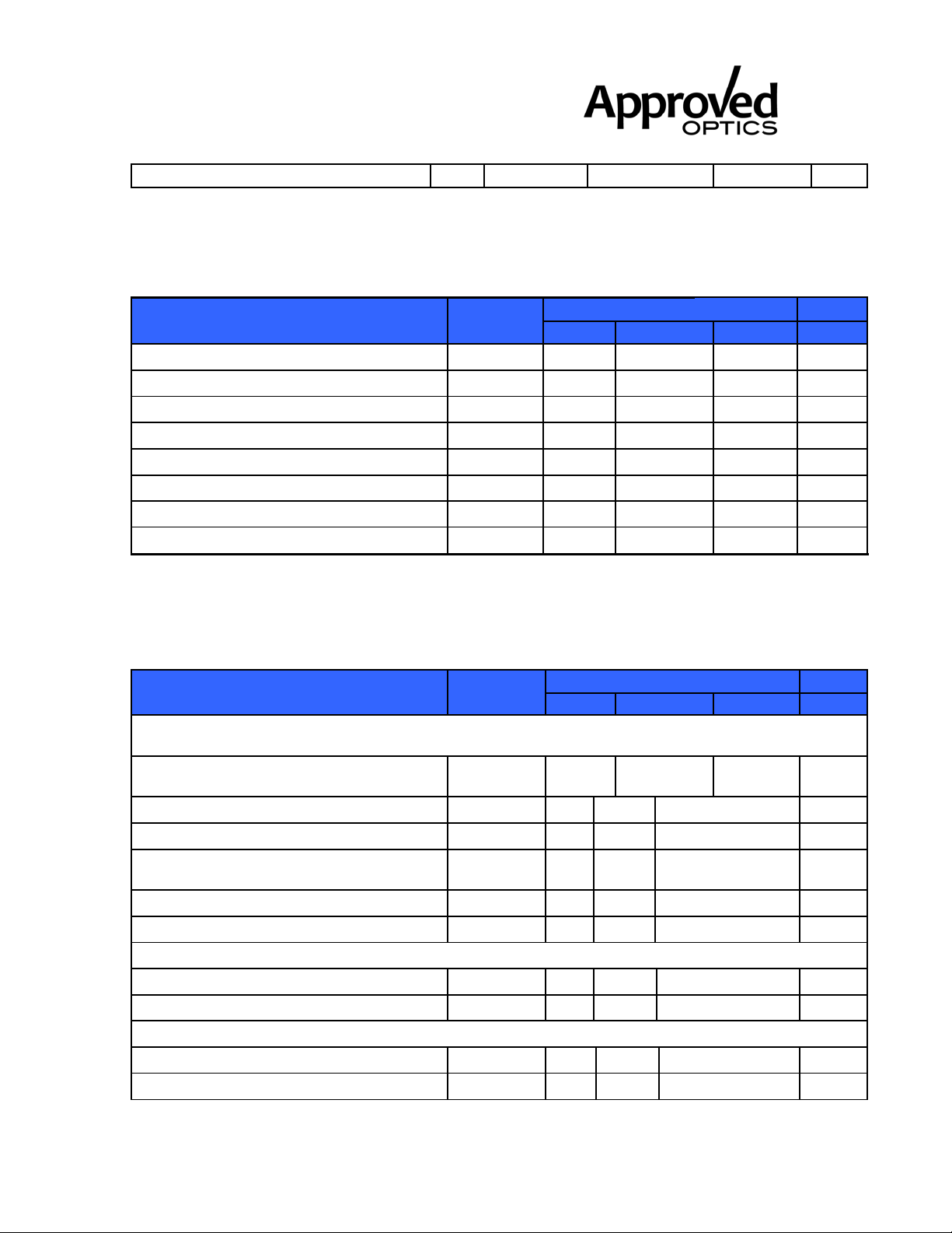
Electrical Characteristics
Recommended Operating Conditions
Parameter Symbol
Operating Case Temperature
Transponder Total Power Consumption
Supply Voltage +5.0 V
Supply Current +5.0 V
Supply Voltage +3.3 V
Supply Current +3.3 V
Supply Voltage APS
Supply Current APS
.
TC
P
VCC5
ICC5
VCC3
ICC3
VCC aps
ICC aps
min. typ.
0
4.75 5 5.25 V
3.14 3.3 3.47 V
1.152 1.2 1.248 V
1.5 dBm
Values Unit
max.
157 190 mA
55 72 mA
830 850 mA
70 °C
2.2 W
Electrical DC Characteristics
(VCC5= 4.75 V to 5.25 V, VCC3= 3.14 V to 3.47 V, VCCaps= 1.152 V to 1.248 V, TC= 0°C to 70°C)
Parameter Symbol
1.2 V CMOS (1.8 V CMOS Compatible1)) I/O DC Characteristics (PRTAD; LASI; RESET;
TX_ONOFF)
External Pull-up Resistor for Open
Drain
Output High Voltage2)
Output Low Voltage2)
Input High Voltage
Input Low Voltage
Input Pull-down Current3)
XAUI I/O DC Characteristics (TXLANE[0..3]; RXLANE[0..3])
Differential Input Amplitude (pk-pk) 4)
Differential Output Amplitude (pk-pk) 4)
MDIO I/O DC Characteristics (MDIO; MDC)
Output Low Voltage5)
Output Low Current
Rpullup
Voh
Vol
Vih
Vil
Ipd
Vin_xaui
Vout_xaui
VOL
IOL
min.
10
1
0.8
4
20
200
800
–0.3
Values Unit
typ. max.
22 kΩ
0.15 V
1.5 V
0.36 V
120 μA
2500 mV
1600 mV
0.2 V
20 mA
V
Approved Optics, Inc. www.ApprovedOptics.com
Page 2 of 8
Page 3
J8436A-A
X2-SR 10GB Module
850nm, 300m, MMF, SC RoHS6
_______________________________________________________
Input High Voltage
Input Low Voltage
Pull-up Supply Voltage
Input Capacitance
Load Capacitance
External Pull-up Resistance
1) For 1.8 V CMOS Voh= 1.65 V min., Vol= 0.15 V max., Vih= 1.17 V min., Vil= 0.63 V max.
2) Rpull-up = 10 kΩ to 1.8 V.
3) Vin = 1.8 V.
4) AC coupled.
5) IOL = 100 μA
VIH
VIL
VPU
CIN
CLOAD
RLOAD
0.84
–0.3
0.84 1.2 1.5 V
200
1.5 V
0.36 V
10 pF
470 pF
Ω
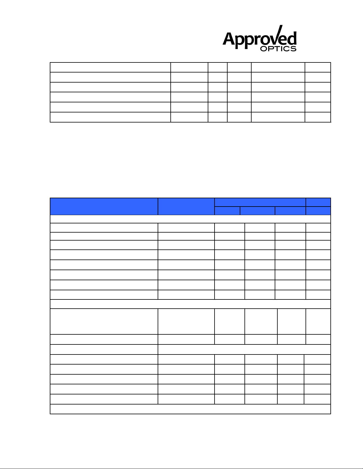
Electrical AC Characteristics
(VCC5 = 4.75 V to 5.25 V, VCC3 = 3.14 V to 3.47 V, VCCaps= 1.152 V to 1.248 V, TC= 0°C to 70°C)
Parameter Symbol
XAUI Input AC Characteristics (TXLANE[0..3])
Baud Rate RXAUIIN Gbit/s
Fibre Channel 3.1875
Ethernet
Baud Rate Tolerance RTOLXAUI –100
Differential Input Impedance ZINXAUI 80 100 120 Ω
Differential Return Loss1)
Input Differential Skew2)
Jitter Amplitude Tolerance3)
XAUI Output AC Characteristics (RXLANE[0..3])
Baud Rate Fibre Channel Ethernet RXAUIOUT
|S11| 10
tSKEWIN
JXAUITOL
min.
Values Unit
typ. max.
3.125
100 ppm
75 ps
0.65 UIp-p
Gbit/s
dB
3.1875
3.125
Baud Rate Variation RXAUIVAR –100
XAUI Eye Mask (far-end) According to IEEE 802.3ae and 10G Fibre Channel
Output Differential Skew
Output Differential Impedance ZOUTXAUI 80 100 120 Ω
Differential Output Return Loss1)
Total Jitter4)
Deterministic Jitter4)
Power-On Reset AC Characteristics
tSKEWOUT
|S22| 10
TJXAUI
DJXAUI
100 ppm
15 ps
dB
0.35 UI
0.37 UI
Approved Optics, Inc. www.ApprovedOptics.com
Page 3 of 8
Page 4
J8436A-A
X2-SR 10GB Module
850nm, 300m, MMF, SC RoHS6
_______________________________________________________
Power-On Reset and TX_ONOFF
Characteristics
MDIO I/O AC Characteristics (MDIO; MDC)
MDIO Data Hold Time
MDIO Data Setup Time
Delay from MDC Rising Edge to
MDIO Data Change
MDC Clock Rate
1) 100 MHz to 2.5 GHz.
2) At crossing point.
3) Per IEEE Std 802.3ae.
4) At near-end, No pre-equalization, 1 UI = 320 ps.
According to X2 MSA Issue 3.0, 2002-9-18
tHOLD
tSU
tDELAY
ƒMAX
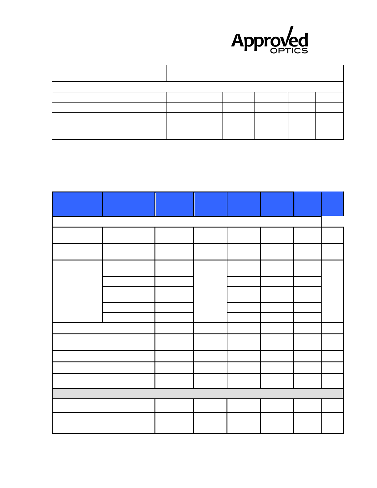
Optical Characteristics
Bandwidth
Parameter
Min Modal
(MHz*Km)
Transmitter
Nominal
Wavelength
Spectral
Width
62.5/125 m
MMF
50/125 m MMF 400 2
Operating
Range
62.5/125 m
MMF
50/125 m MMF 500 2
50/125 m MMF 2000 2
Nominal Signaling Speed
Launch Power in OMA
Average Launch Power
Condition
s Symbol Min Typ Max
lTRP 840 850 860 nm
160
200 2
Iop
fOPT 9.95
PoptOM
Poptavg
A
10
10
300 ns
2.5 MHz
Unit
0.4 0.45 nm
2
-4.3
-7.3 -2.6 -1 dBm
26
66
33
82
300
10.71 GBd
dBm
ns
ns
s
m
Extinction Ratio
Relative Intensity Noise
Receiver
Center Wavelength
Receiver Sensitivity
Approved Optics, Inc. www.ApprovedOptics.com
in OMA,
BER 10-12
@ 231 -11)
ER 3.5 5.5
RIN
840 850 860 nm
PINS
-13.5 -11.1
-128
Page 4 of 8
dB
dB/H
z
dBm
Page 5
J8436A-A
X2-SR 10GB Module
850nm, 300m, MMF, SC RoHS6
_______________________________________________________
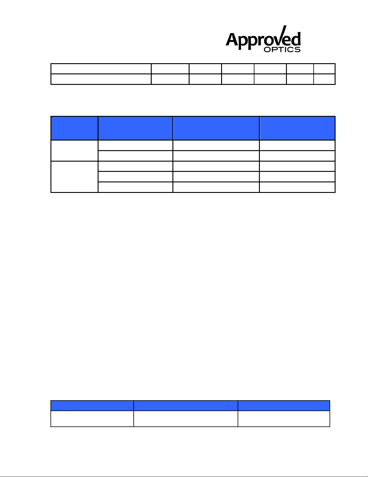
Stressed Receiver Sensitivity in OMA PIN
-7.5 dBm
Saturation Input Power
PSAT
1 dBm
General Specifications
Optical Interface Standard Specifications
Minimum Modal
Standard Fiber Type
IEEE
Fibre
Channel
Notes:
1) Operating range as defined by IEEE and Fibre Channel standards. Longer reach possible
depending upon link implementation.
62.5 μm MMF 160 2 to 26
50 μm MMF 400 2 to 66
62.5 μm MMF 200 0.5 to 33
50 μm MMF 500 0.5 to 82
50 μm MMF 2000 0.5 to 300
Bandwidth at 850 nm
(MHz*km)
Operating Range 1)
(meters)
Environmental Performance
Operating case temperature: 0°C to +70°C
Operating humidity: 0% -95% RH non-condensing
Fibers and Connectors
The transponder has SC receptacles for both Tx and Rx. The transponder is designed
for multimode SC cables, 0° polished endface (PC).
Rail and Mechanical Mounting Requirements
The X2 rail system required to mount the X2 module is fully defined by the MSA. (Tyco
Electronics part number 1367608-1: designed for belly to belly applications; and 1367610-1,
designed for single sided board mount to fit into the standard host PCB footprint; or
equivalent). For further details please refer to vendor-supplied information.
Regulatory Compliance
Feature Standard Comments
ESD: Electrostatic
Discharge to the
Approved Optics, Inc. www.ApprovedOptics.com
EIA/JESD22-A114-B (MIL-STD
883D
Class 1a (> 500 V)
Page 5 of 8
Page 6

J8436A-A
X2-SR 10GB Module
850nm, 300m, MMF, SC RoHS6
_______________________________________________________
Electrical Pins (HBM) Method 3015.7)
Immunity: Against
Electrostatic Discharge
(ESD) to the Module
Receptacle
Immunity: Against Radio
Frequency
Electromagnetic Field
Emission: FCC 47 CFR Part 15,
Electromagnetic
Interference
(EMI) Class B CISPR 22
EN 61000-4-2 IEC 61000-4-2
EN 61000-4-3 IEC 61000-4-3
Class B EN 55022
Discharges ranging from ±2
kV to ±25 kV to the front end
/ faceplate / receptacle
cause no damage to module
(under recommended
conditions).
With a field strength of 10
V/m, noise frequency ranges
from 10 MHz to 2 GHz. No
effect on module
performance between the
specification limits.
Noise frequency range:30
MHz to 40 GHz
Radiated emission does not
exceed specified
limits when measured with
module inside a
shielding enclosure with a
MSA conforming cutout
Approved Optics, Inc. www.ApprovedOptics.com
Page 6 of 8
Page 7
J8436A-A
X2-SR 10GB Module
850nm, 300m, MMF, SC RoHS6
_______________________________________________________
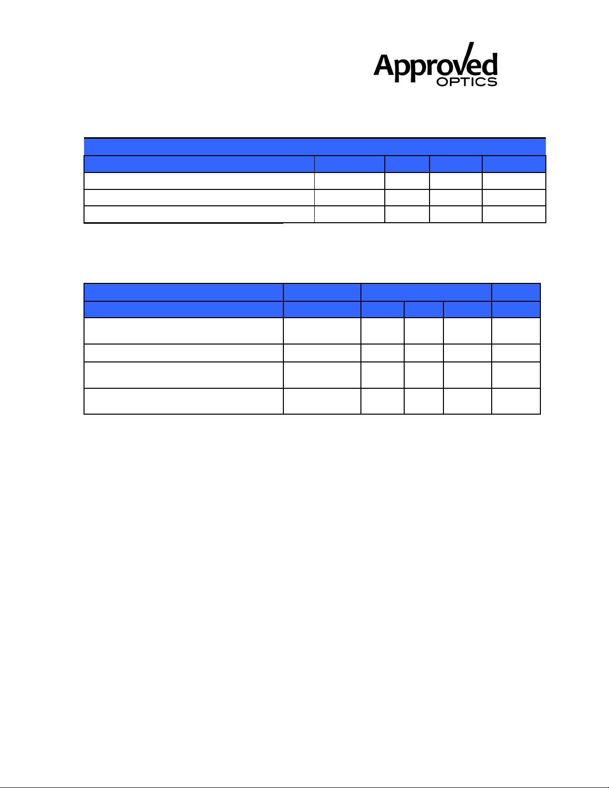
DOM Parameters
Parameter Values Unit
min.
typ.
Max
typ. max.
40
16
25
10 %
3 dB
3 dB
Min.
Laser Bias Current Monitor Accuracy 2)
Transmit Power Monitor Accuracy 3)
Receive Power Monitor Accuracy 3)
1) 0 to 70°C case temperature.
2) 0 to 12.5 mA.
3) -8.2 dBm to +0.5 dBm.
Parameter Symbol Values Unit
Module Retention Force (latch
strength)
Module Insertion Force FIN
Module Extraction Force (with kick-
out)
Module Extraction Force (without kickout)
FRET 200 N
FEXT-K
FEXT
-10
-3
-3
N
N
N
Eye Safety
This laser based multimode transceiver is a Class 1 product. It complies with IEC 608251 Ed.2: 2007 and FDA performance standards for laser products (21 CFR 1040.10 and
1040.11) except for deviations pursuant to Laser Notice 50, dated June 24, 2007.
Approved Optics, Inc. www.ApprovedOptics.com
Page 7 of 8
Page 8

J8436A-A
X2-SR 10GB Module
850nm, 300m, MMF, SC RoHS6
_______________________________________________________
Contact Information
Approved Optics is a leading supplier of Network Transceivers and Connectivity
products to Channel Partners, Resellers, and OEMs. With more than 9 years of direct
industry experience, our products are resident in the most demanding and mission
critical functional networks Worldwide. We serve as a Master Distributor to the largest
CM’s in the world and deploy the most rigorous testing and firmware management
programs to bring the highest level of functional product to the market at a cost that
makes sense.
Corporate Offices:
Approved Optics
Tel: 800.590.9535
Web: http://www.ApprovedOptics.com
Approved Optics, Inc. www.ApprovedOptics.com
Page 8 of 8
 Loading...