

A P Products GmbH
The A P Products
Test-Clip Special
LINECARD
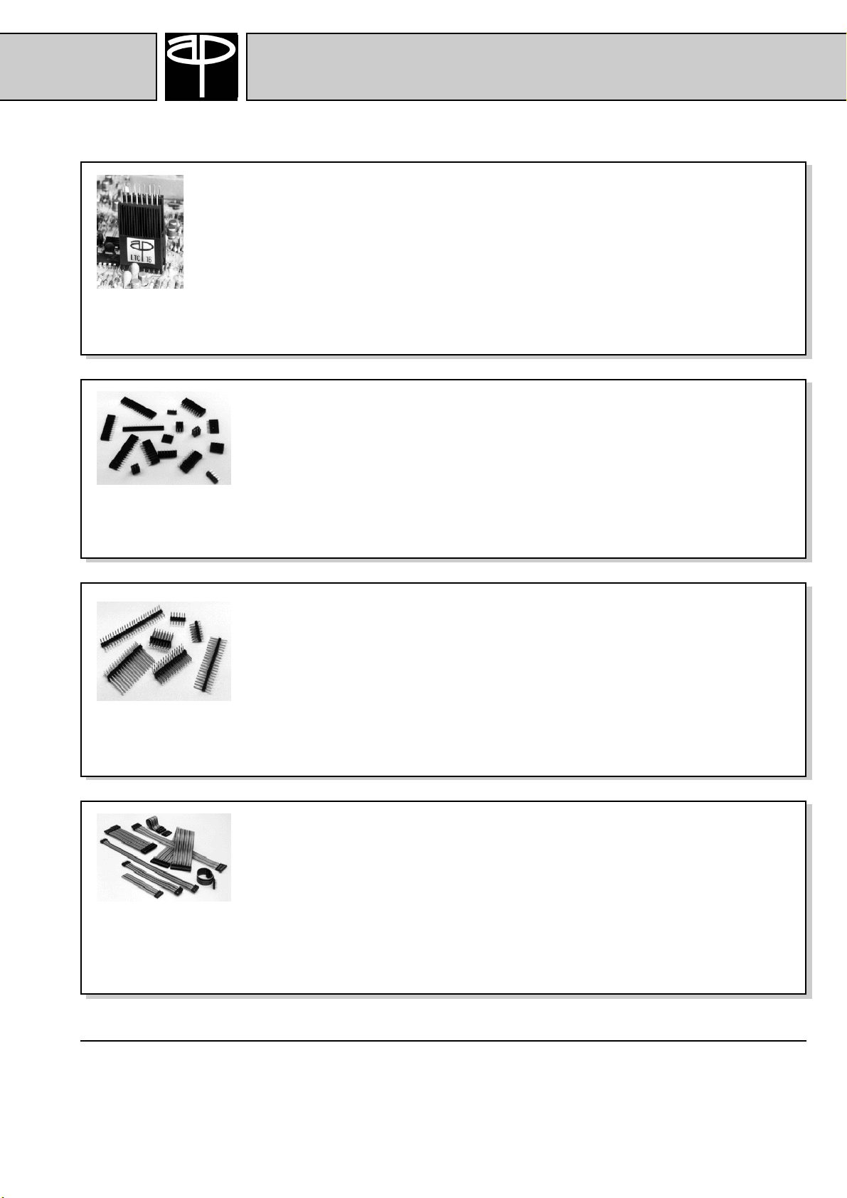
IC Test Clips
A P Products Test Clips the industry standard for faster, easier DIP IC testing, quality
control inspection and field service. The Test Clips provide easy attachment, „handsfree“ testing and positive clamping. Reliable contacts and rugged construction allow a
save way for testing.
Over 150 models to fit every size DIP up to 64 pins
Nailhead and connector compatible „headless“ available
Female Header
The wide standard assortment of female headers include single, double and triple
row female headers with up to 36 pins per row which can easily be cut down to
any desired length.
A P Products
A variety of gold and tin platings available
Mate with industry standard connectors or headers with contacts spaced on 2,54mm
Male Header
A P Products offers a wide range of either custom made or standard male headers.
The wide assortment of standard male headers include single, double and triple
row, straight and right angle, gold and solder plating and in various pinlength up
to 36 pins per row.
2,36mm / 5,97mm / 8,07mm interface area
Mate with industry standard connectors or headers with contacts spaced on 2,54mm
Molded-On Cable
Molded-On cable assemblies are suited for board to board interconnects. As a
result of the „Molded-On“ technology cable and contacts are one piece and
therefore inseparable. There are no individual components to become apart.
Different cable and connector styles available
Custom configurations welcome
100% factory tested
A P Products GmbH
Postfach 1158
D-71089 Weil im Schönbuch
Deutschland
Tel.: +49-7157-5348-0
Fax: +49-7157-5348-39
Web: www.ap-products.de
E-mail: info@ap-products.de
A P Products Ltd.
80 Cromwell Road
Saffron Walden, CB11 4BE
Great Britain
Tel.: +44-1799-526602
Fax: +44-1799-521408
Web: www.ap-products.co.uk
E-mail: info@ap-products.co.uk
A P Products S.r.l.
Viale Abruzzi, 87
I-20131 Milano
Italia
Tel.: +39-02-29404697
Fax: +39-02-29523280
Web: www.ap-products.com
E-mail: info-i@ap-products.com
AP1100
A P Products GmbH
TEST
-
CLIP
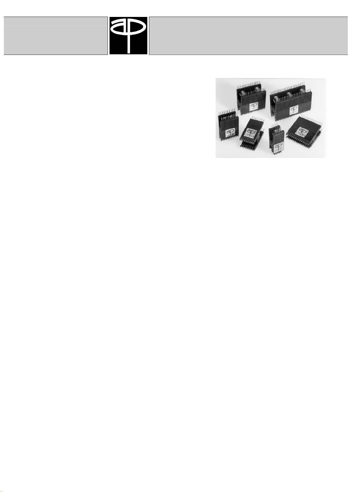
The IC Test-Clip for fast, safe access to DIP Leads
Since 1967 in the market, our Test-Clip has remained the industry
standard for faster easier DIP IC Testing, quality control inspection,
and field service. A P Products Test-Clips have become an
indispensable tool to the electronic industry.
We're introducing today the industry largest selection of Test-Clips.
With 144 models to fit every size DIP up to 64-pins and both nailed
and connector-compatible "headless" leads available in every size,
A P Products has just the right Test-Clip to meet your DIP testing
requirements.
• Easy attachment
Narrow nose shape for working on high density PC-boards. Fits onto IC's with only 2,5 mm between leads and
adjacent components.
• Positive clamping
The heavy duty industrial grade metal springs provide a firm positive grip to the DIP under test. The weight of the
probes and test leads can't disturb connections, eliminating intermittents and false readings.
• Reliable contacts
Proven contact wiping action for optimum reliability. New are "Paint Cut" contacts for ICs with antistatic protection
coating, as often used in military applications. These contacts will cut through the protective coating. Stripping the
coat prior to testing is no longer necessary. The test marks can easily be touched up after testing.
• Save way to test
The contact comb fits between DIP leads to eliminate any possibility of shorting out chips.
• Rugged construction
Body material is tough, engineering grade glass filled PBT. The contacts are made from hardened Nickel Silver.
Hinge design with steel pivot pin for smooth, long lasting use.
Specifications:
Plastic: PBT, glass filled (30%), UL 94 VO
Contacts: CuNi18Zn20, unplated or gold plated
Temp. Range: -55 °C to +165 °C
Rel. Humidity: <80%
Max. Current: 2 A
Max. Voltage: 250 V
Test Voltage: Contact - Contact = 1000 V
Contact - Ground = 1500 V
3
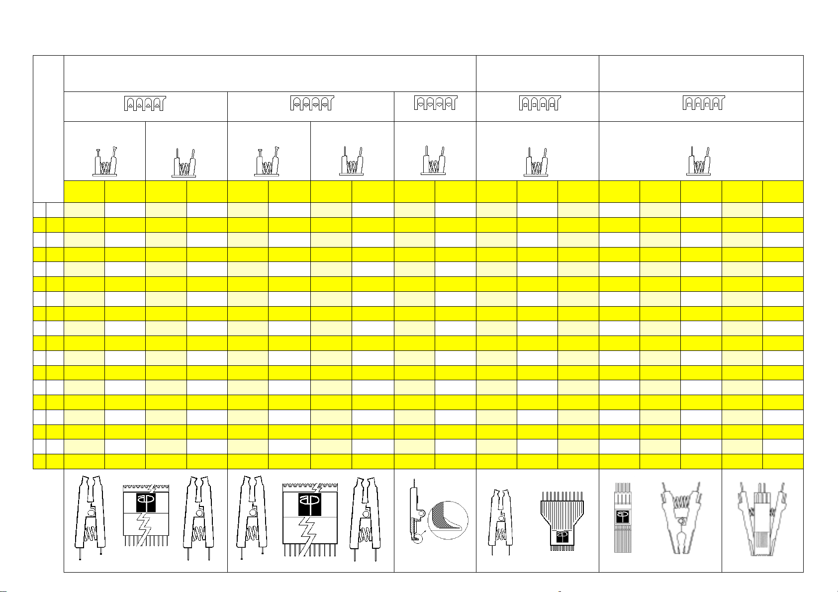
A P Products™ Test Clip Product Matrix
DIL / DIP Testclips
Shrink DIP
Testclips
Standard Model Connector Compatible Connector Compatible
(with Nail Heads) (with Headless Heads) (with Nail Heads) (with Headless Heads) (with Headless Heads)
Lead
Count /
Plating
8
Alloy 900695 900690-08 900741-08 900737-08
Gold 900743-08 900739-08 900741-08-AU 900737-08-AU
14
Alloy 900698 900690-14 900741-14 900737-14
Gold 900743-14 900739-14 900741-14-AU 900737-14-AU
16 900790-16 900789-16
Alloy 900700 900702 900690-16 900689-16 900741-16 900740-16 900741- 900736-16
Gold 900743-16 900742-16 900739-16 900738-16 900741-16-AU 900740-16-AU 900741- 900736-08-AU
18
Alloy 900703 900690-18 900741-18 900737-18
Gold 900743-18 900739-18 900741-18-AU 900737-18-AU
20
Alloy 900704 900690-20 900741-20 900737-20
Gold 900743-20 900739-20 900741-20-AU 900737-20-AU
22 900789-22 900790-22
Alloy 900706 900705 900689-22 900690-22 900740-22 900741-22 900736-22 900737-22
Gold 900742-22 900743-22 900738-22 900739-22 900740-22-AU 900741-22-AU 900736-22-AU 900737-22-AU
24 900789-24 900790-24
Alloy 900715 900714 900689-24 900690-24 900740-24 900741-24 900736-24 900737-24
Gold 900742-24 900743-24 900738-24 900739-24 900740-24-AU 900741-24-AU 900736-24-AU 900737-24-AU
28
Alloy 900717 900718 900689-28 900690-28 900740-28 900741-28 900736-28 900737-28
Gold 900742-28 900743-28 900738-28 900739-28 900740-28-AU 900741-28-AU 900736-28-AU 900737-28-AU
32
Alloy 900719 900690-32 900741-32 900737-32
Gold 900743-32 900739-32 900741-32-AU 900737-32-AU
36
Alloy 900720 900690-36 900741-36 900737-36
Gold 900743-36 900739-36 900741-36-AU 900737-36-AU
40
Alloy 900722 900690-40 900741-40 900737-40
Gold 900743-40 900739-40 900741-40-AU 900737-40-AU
42 Alloy 900747-42
Gold
Alloy
44
Gold
48 Alloy 900724 900690-48 900741-48 900737-48 900790-48
Gold 900743-48 900739-48 900741-48-AU 900737-48-AU
Alloy
52
Gold
64 Alloy 900726* 900690-64* 900741-64* 900737-64* 900790-64* 900747-64 900748-64
Gold 900743-64* 900739-64* 900741-64-AU* 900737-64-AU*
Alloy
68
Gold
Alloy
84
Gold
DIP DIP DIP DIP DIP DIP DIP DIP DIP DIP Shrink-DIP Shrink-DIP Shrink-DIP SOIC SOIC SOJ LCC PLCC
.300" wide
(7,62 mm)
Duck Bill Contacts Knife Edge Contacts Paint Cut Contacts
.600" wide
(15,24 mm)
.300" wide
(7,62 mm)
.600" wide
(15,24 mm)
Standard Model Connector Compatible
Part Numbers
.300" wide
(7,62 mm)
.600" wide
(15,24 mm)
Part Numbers Part NumbersPart Numbers Part Numbers
.300" wide
(7,62 mm)
.600" wide
(15,24 mm)
.300" wide
(7,62mm)
900790-08
900790-14
900790-18
900790-20
900789-28 900790-28
.600" wide
(15,24 mm)
900790-32
900790-36
900790-40
900746-28 900747-28
.400" wide
(10,16 mm)
Connector Compatible
(with Headless Heads)
Part Numbers
.600" wide
(15,24 mm)
900747-52
.750" wide
(19,05 mm)
Surface Mount Test Clips
Square ContactsSquare Contacts
Connector Compatible
(with Headless Heads)
Part Numbers
.150" wide
(3,81 mm)
923650-08
923655-08
923650-14
923655-14
923650-16
923655-16
923650-18
923655-18
923650-20
923655-20
923650-24
923655-24
923650-28
923655-28
.300" wide
(7,62 mm)
923660-08
923665-08
923660-14
923665-14
923660-16
923665-16
923660-18
923665-18
923660-20
923665-20
923660-24
923665-24
923660-28
923665-28
.300" wide
(7,62 mm)
923660-20
923665-20
923660-24
923665-24
923660-28
923665-28
923680-20
923685-20
923680-28
923685-28
923680-44
923685-44
923680-52 923670-52
923680-68
923685-68
923680-84
923685-84
923670-20
923675-20
923670-28
923675-28
923670-44
923675-44
923670-68
923675-68
923670-84
923675-84
* 64 position DIL Test Clip and IC are .900" (22,86 mm) wide
A P Products GmbH
DIP TEST
-
CLIP
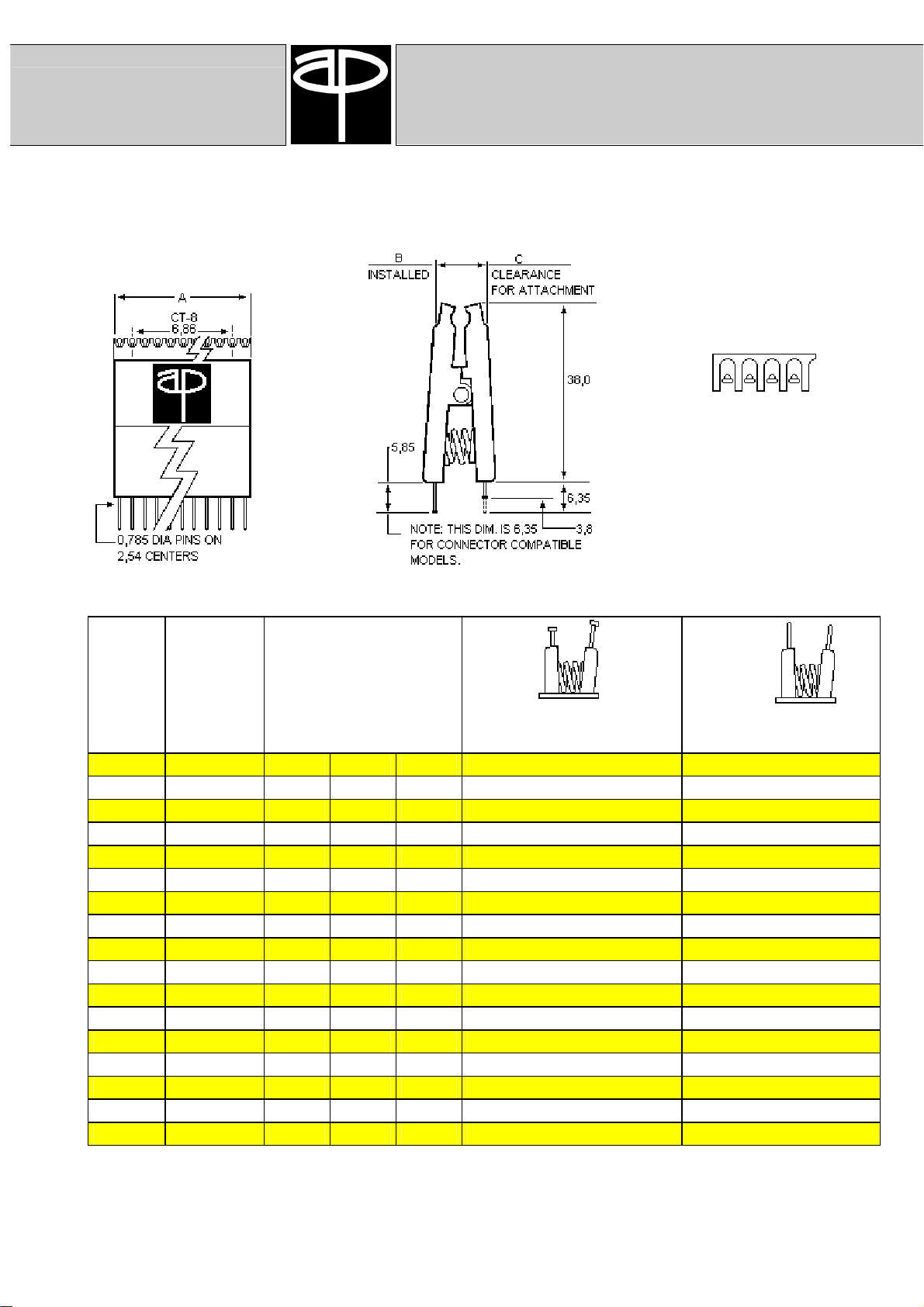
Standard
The Standard Test-Clip
Flat contacts for maximum interface surface area.
Top view showing flat contacts
Dimensions
Number
of pins
08 7,62 / 0,3 16,06 12,20 12,95 900695 900743-08 900690-08 900739-08
14 7,62 / 0,3 18,60 12,20 12,95 900698 900743-14 900690-14 900739-14
16 7,62 / 0,3 21,13 12,20 12,95 900700 900743-16 900690-16 900739-16
16 15,24 / 0,6 21,13 19,30 20,57 900702 900742-16 900689-16 900738-16
18 7,62 / 0,3 23,67 12,20 12,95 900703 900743-18 900690-18 900739-18
20 7,62 / 0,3 26,21 12,20 12,95 900704 900743-20 900690-20 900739-20
22 7,62 / 0,3 28,75 12,20 12,95 900706 900742-22 900689-22 900738-22
22 15,24 / 0,6 28,75 19,30 20,57 900705 900743-22 900690-22 900739-22
24 7,62 / 0,3 31,29 12,20 12,95 900715 900742-24 900689-24 900738-24
24 15,24 / 0,6 31,29 19,30 20,57 900714 900743-24 900690-24 900739-24
28 7,62 / 0,3 36,37 12,20 12,95 900717 900742-28 900689-28 900738-28
28 15,24 / 0,6 36,37 19,30 20,57 900718 900743-28 900690-28 900739-29
32 15,24 / 0,6 41,45 19,30 20,57 900719 900743-32 900690-32 900739-32
36 15,24 / 0,6 46,53 19,30 20,57 900720 900743-36 900690-36 900739-36
40 15,24 / 0,6 51,61 19,30 20,57 900722 900743-40 900690-40 900739-40
48 15,24 / 0,6 61,77 19,30 20,57 900724 900743-48 900690-48 900739-48
64 22,86 / 0,9 82,10 26,67 27,43 900726 900743-64 900690-64 900739-64
row to row
mm / inch
Dimensions
A
(mm)
B
C
Nickel-Silver Gold
Part number
Part number
Nickel-Silver Gold
5

Knife-Edge
TEST
-
CLIP
The Knife-Edge Test-Clip
Specially formed contacts to cut through dirt build-up on IC pins.
A P Products GmbH
Top view showing knife-edge
Dimensions
Number
of pins
08 7,62 / 0,3 16,06 12,20 12,95 900741-08 900737-08 900737-08-AU
14 7,62 / 0,3 18,60 12,20 12,95 900741-14 900737-14 900737-14-AU
16 7,62 / 0,3 21,13 12,20 12,95 900741-16 900737-16 900737-16-AU
16 15,24 / 0,6 21,13 19,30 20,57 900740-16 900736-16 900736-16-AU
18 7,62 / 0,3 23,67 12,20 12,95 900741-18 900737-18 900737-18-AU
20 7,62 / 0,3 26,21 12,20 12,95 900741-20 900737-20 900737-20-AU
22 7,62 / 0,3 28,75 12,20 12,95 900740-22 900736-22 900736-22-AU
22 15,24 / 0,6 28,75 19,30 20,57 900741-22 900737-22 900737-22-AU
24 7,62 / 0,3 31,29 12,20 12,95 900740-24 900736-24 900736-24-AU
24 15,24 / 0,6 31,29 19,30 20,57 900741-24 900737-24 900737-24-AU
28 7,62 / 0,3 36,37 12,20 12,95 900740-28 900736-28 900736-28-AU
28 15,24 / 0,6 36,37 19,30 20,57 900741-28 900737-28 900737-28-AU
32 15,24 / 0,6 41,45 19,30 20,57 900741-32 900737-32 900737-32-AU
36 15,24 / 0,6 46,53 19,30 20,57 900741-36 900737-36 900737-36-AU
40 15,24 / 0,6 51,61 19,30 20,57 900741-40 900737-40 900737-40-AU
48 15,24 / 0,6 61,77 19,30 20,57 900741-48 900737-48 900737-48-AU
64 22,86 / 0,9 82,10 26,67 27,43 900741-64 900737-64 900737-64-AU
row to row
mm / inch
Dimensions
A
(mm)
B
C
Part number
Nickel-Silver
Part number
Nickel-Silver Gold
contacts
6

A P Products GmbH
TEST
-
CLIP
PAINT CUT
The Paint-Cut Test-Clip
Specially formed and hardened contacts designed to cut through antistatic paint on PC-Boards.
Top-view showing
contacts
Side-view showing contacts
Paint Cut contacts are for ICs with antistatic protection coating, as often used in military applications. These
contacts will cut through the protective coating. Stripping the coat prior to testing is no longer necessary. The test
marks can easily be touched up after testing
Number
of pins
24 7,62 / 0,3 31,29 12,20 12,95 900789-24
28 7,62 / 0,3 36,37 12,20 12,95 900789-28
08 7,62 / 0,3 16,06 12,20 12,95 900790-08
14 7,62 / 0,3 18,60 12,20 12,95 900790-14
16 7,62 / 0,3 21,13 12,20 12,95 900790-16
18 7,62 / 0,3 23,67 12,20 12,95 900790-18
20 7,62 / 0,3 26,21 12,20 12,95 900790-20I
24 15,24 / 0,6 31,29 19,30 20,57 900790-24
28 15,24 / 0,6 36,37 19,30 20,57 900790-28
40 15,24 / 0,6 51,61 19,30 20,57 900790-40
48 15,24 / 0,6 61,77 19,30 20,57 900790-48
64 22,86 / 0,9 82,10 26,67 27,43 900790-64
Dimensions
row to row
A
Dimensions (mm)
B
C
Part number
7
Shrink-DIP
TEST
-
CLIP
A P Products GmbH
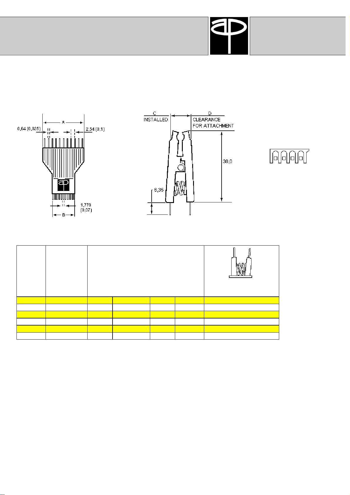
The Shrink-DIP Test-Clip
1,778 mm on the interface side and 2,54 mm on the connector side make the Test-Clip compatible to
standard connectors.
Dimensions
Number
of pins
28 10,16 / 0,4" 36,67 25,27 16,25 17,00 900746-28
28 15,24 / 0,6" 36,67 25,27 19,30 20,57 900747-28
42 15,24 / 0,6" 54,15 37,72 19,30 20,57 900747-42
52 15,24 / 0,6" 66,85 46,61 19,30 20,57 900747-52
64 15,24 / 0,6" 82,10 57,28 19,30 20,57 900747-64
64 19,05 / 0,75" 82,10 57,28 24,13 25,40 900748-64
row to row
mm / inch
A
Dimensions
(mm)
B
C D
Part number
Nickel-Silver
View showing contacts
in IC mating area
8
A P Products GmbH
TEST
-
CLIP
Small Outline
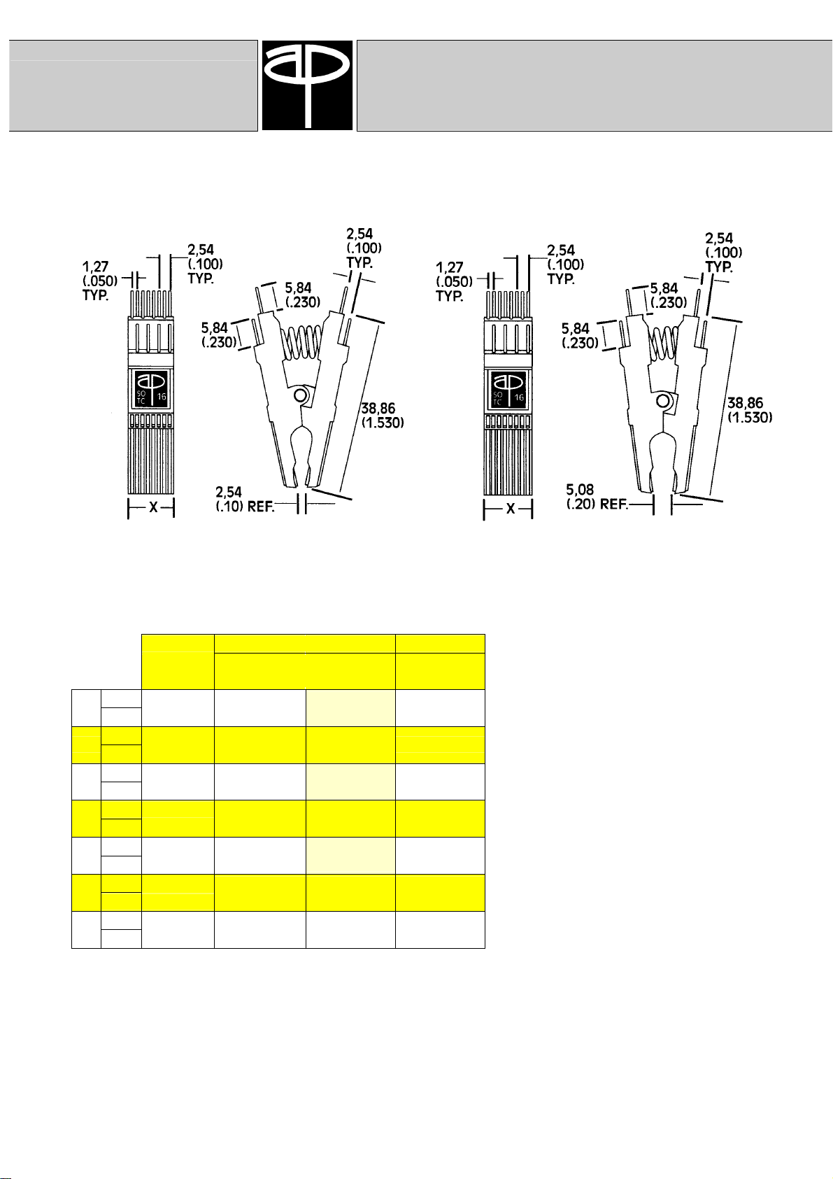
The Small-Outline Test-Clip
For .150" and .300" small outline ICs. The connector end is staggered to accommodate standard pitch connectors.
Alloy 5,59 mm
8
Gold (0,220")
Alloy 9,40 mm
14
Gold (0,370")
Alloy 10,67 mm
16
Gold (0,420")
Alloy 11,97 mm
18
Gold (0,470")
Alloy 13,21 mm
20
Gold (0,520"
Alloy 15,75 mm
24
Gold (0,620")
Alloy 18,29 mm
28
Gold (0,720")
"Narrow" Version
(0,150" wide IC's)
SOIC SOIC SOJ
"X"
Dimension
.150" wide
(3,81 mm)
923650-08
923655-08
923650-14
923655-14
923650-16
923655-16
923650-18
923655-18
923650-20
923655-20
923650-24
923655-24
923650-28
923655-28
.300" wide
(7,62 mm)
923660-08
923665-08
923660-14
923665-14
923660-16
923665-16
923660-18
923665-18
923660-20
923665-20
923660-24
923665-24
923660-28
923665-28
.300" wide
(7,62 mm)
923660-20
923665-20
923660-24
923665-24
923660-28
923665-28
"Wide" Version
(0,300" wide IC's)
The SOTC is specially designed for "Small
Outline IC's" (IC's with a small circumference).
Although the distance between pins at the end
of the IC is only 1,27 mm (0,050''), a distance
of 2,54 mm between pins is reached at the tap
end.
This pitch enables an easy attachment of the
test point and ensures that unnecessary short
circuits are avoided.
The standard 0,64 mm square pins enable an
easy attaching of the respective connectors or
"wire wrapping".
Like all of our Test-Clips, the SOTC has an
extra strong pressure spring, which ensures a
safe contact. Furthermore, it has an insulator
in order to avoid any short circuits. With this
small Test-Clip even SOIC's having a distance
of only 0,64 mm can be tested.
9
Surface Mount
TEST
-
CLIP
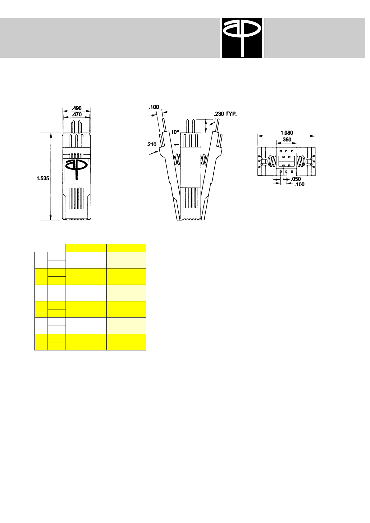
The PLCC Test-Clip
All four sides open simultaneously for easy attachment on PLCC or LCC chips.
Alloy
20
Gold
Alloy
28
Gold
Alloy
44
Gold
Alloy
52
Gold
Alloy
68
Gold
Alloy
84
Gold
LCC PLCC
923680-20
923685-20
923680-28
923685-28
923680-44
923685-44
923680-52
923685-52
923680-68
923685-68
923680-84
923685-84
923670-20
923675-20
923670-28
923675-28
923670-44
923675-44
923670-52
923675-52
923670-68
923675-68
923670-84
923675-84
This Test-Clip is for testing Plastic Leaded Chip Carrier (PLCC) style
integrated circuits. The unique action wedge design with all four
sides opening simultaneously provides a faster and easier
attachment to the PLCC.
The helical compression spring and insulating contact combs insure
integrity in contact when testing. Our narrow body design allows
components to be tested with as little as 2,54 mm (0,1") lead-to-lead
spacing, side stackable at 0,200" lead-to-lead spacing.
Probe access points are immediately visible for fast and safe
individual lead testing, while staggered contact rows on 0,100"
centers allow for easy probe attachment and help prevent accidental
shorting of adjacent probes, Industry standard 0,635 mm square
contact pins permit easy attachment of female socket connectors or
wire wrapping.
A P Products GmbH
10

A P Products GmbH
Assessories
Logical Connection
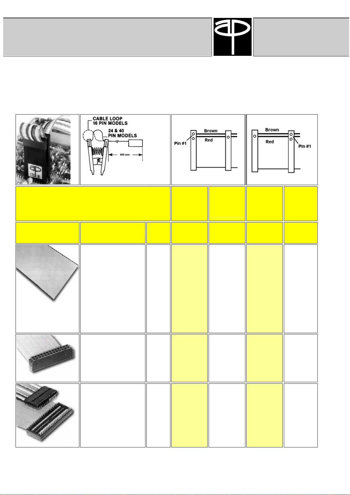
The Logical Connection
Remote test equipment can be easily connected to a PCB when the performance proven
A P Products IC Test-Clip is combined with our complete, tested, ready-to-use cable
assembly.
We call this combination "The Logical Connection". It is the ideal connection from a
logic analyzer to an IC.
On one end, a pair of single-row socket connectors attach to the pins of a connectorcompatible model Test-Clip. On the other end the cable is left open for an easy attachment
of customer specific connectors. Logical Connections with preinstalled connectors are also
available
Logical Connection for Dual Inline
Packages (Through-Hole ICs)
Narrow nose shape
fits high density PC boards; fits onto ICs with only 0,1'' between leads or adjacent
components.
Probe holes
in the back of all connectors allow easy access to individual lines.
Positive clamping
The heavy duty industrial grade metal springs provide a firm positive grip to the DIP
under test. The weight of the probes and test leads can't disturb connections,
eliminating intermittents and false readings.
Cable loop
between connectors allows free actuation of the Test-Clip for clearance over all
package styles.
Molded-on connectors
provide optimum electrical integrity and strain relief. (not available on all configurations)
Custom configurations
can be ordered by contacting factory.
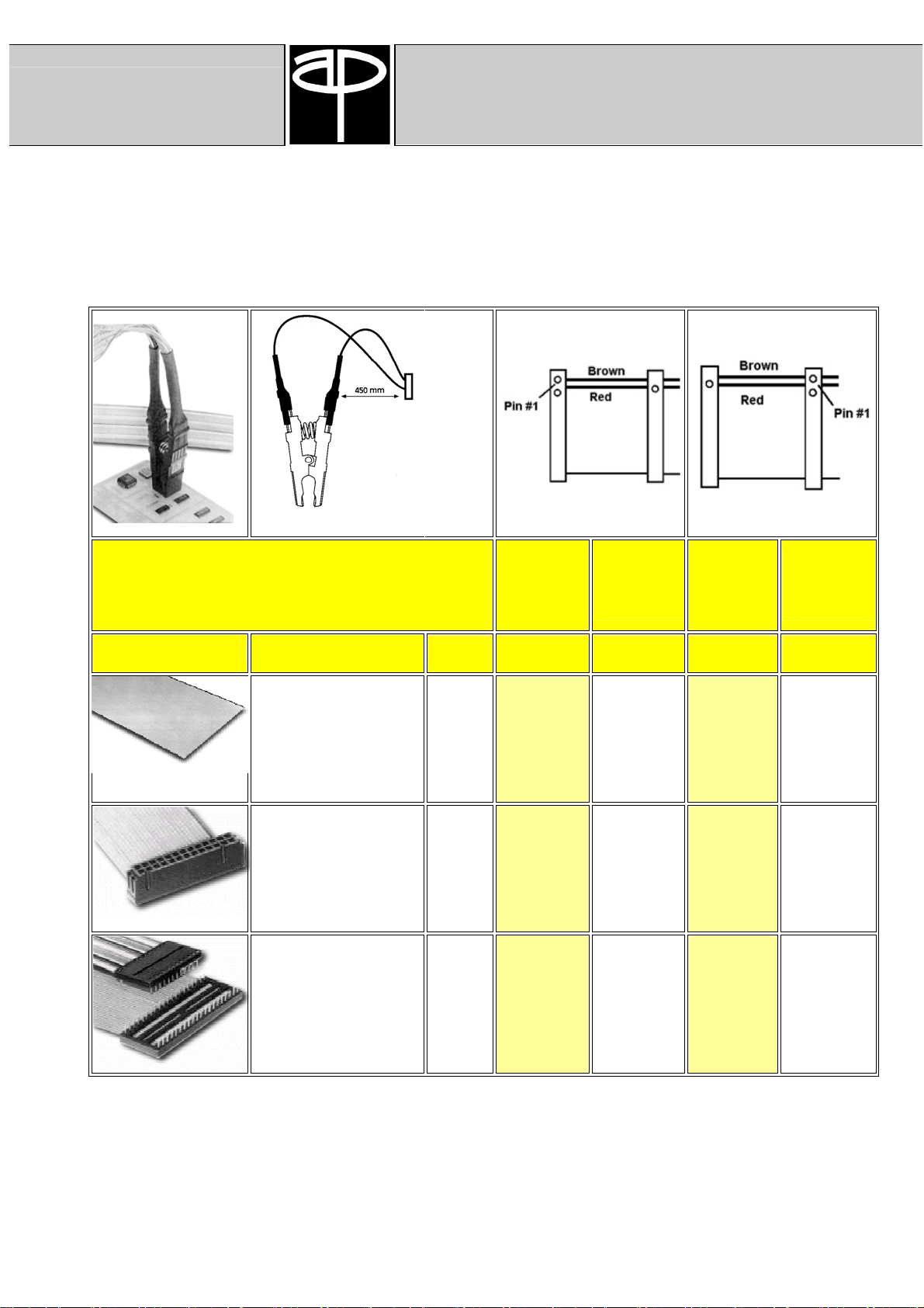
Logical Connection for Shrink DIP
Packages (Through-Hole ICs)
Logical Connection for Small Outline
Packages (Surface Mount ICs)
Logical Connection for PLCC Packages
(Surface Mount ICs)
11
only (No Test
Logical Connection
Assessories
Logical Connection for Dual Inline Packages
A P Products GmbH
(Through-Hole ICs)
Remote End Termination
Connector Description
none 08
Socket Connector
- mates with two rows of
0,635mm (0,025")
square or diameter pins
on 2,54 mm (0,100")
centers.
DIP Connector
- mates with standard
DIP sockets
No. of
Contact
s
14
16
18
20
22
24
28
32
36
40
48
64
14
16
20
26**
40
50**
64
08
14
16
20
24
28
40
Logical
Connection
(Test Clip
and Cable
Assembly)
Part
Number*
923930-08
923930-14
923930-16
923930-18
923930-20
923930-22
923930-24
923930-28
923930-32
923930-36
923880-40
923880-48
923880-64
923931-14
923931-16
923931-20
923931-24
923881-40
923881-48
923881-64
923934-08
923934-14
923934-16
923934-20
923934-24
923934-28
923934-40
Cable
Assembly
Clip)
Part
Number*
922490-08
922490-14
922490-16
922490-18
922490-20
922490-22
922490-24
922490-28
922490-32
922490-36
922590-40
922590-48
922590-64
922491-14
922491-16
922491-20
922491-24
922591-40
922591-48
922591-64
922494-08
922494-14
922494-16
922494-20
922494-24
922494-28
922494-40
Logical
Connection
(Test Clip
and Cable
Assembly)
Part
Number*
923880-08
923880-14
923880-16
923880-18
923880-20
923880-22
923880-24
923880-28
923880-32
923880-36
923930-40
923930-48
923930-64
923881-14
923881-16
923881-20
923881-24
923931-40
923931-48
923931-64
923884-08
923884-14
923884-16
923884-20
923884-24
923884-28
923884-40
Cable
Assembly
only (No
Test
Clip)
Part
Number*
922590-08
922590-14
922590-16
922590-18
922590-20
922590-22
922590-24
922590-28
922590-32
922590-36
922490-40
922490-48
922490-64
922591-14
922591-16
922591-20
922591-24
922491-40
922491-48
922491-64
922594-08
922594-14
922594-16
922594-20
922594-24
922594-28
922594-40
* Part number suffix denotes number of pins in Test Clip.
** On 26 position connectors, position #25 and #26 are unused. On 50 position connectors, position #49 and #50 are unused.
12
A P Products GmbH
Assessories
Logical Connection
Logical Connection for Small Outline Packages
(Surface Mount ICs)
Remote End Termination
Connector Description
none 08
Socket Connector
- mates with two rows of
0,635mm (0,025")
square or diameter pins
on 2,54 mm (0,100")
centers.
DIP Connector
- mates with standard
DIP sockets
No. of
Contacts
14
16
18
20
24
28
10**
14
16
20**
20
26**
34**
08
14
16
18
20
24
28
Logical
Connection
(Test Clip
and Cable
Assembly)
Part
Number*
924930-08
924930-14
924930-16
924930-18
924930-20
924930-24
924930-28
924931-08
924931-14
924931-16
924931-18
924931-20
924931-24
924931-28
924934-08
924934-14
924934-16
924934-18
924934-20
924934-24
924934-28
Cable
Assembly
only (No
Test Clip)
Part
Number*
924490-08
924490-14
924490-16
924490-18
924490-20
924490-24
924490-28
924491-08
924491-14
924491-16
924491-18
924491-20
924491-24
924491-28
924494-08
924494-14
924494-16
924494-18
924494-20
924494-24
924494-28
Logical
Connection
(Test Clip
and Cable
Assembly)
Part
Number*
924880-08
924880-14
924880-16
924880-18
924880-20
924880-24
924880-28
924881-08
924881-14
924881-16
924881-18
924881-20
924881-24
924881-28
924884-08
924884-14
924884-16
924884-18
924884-20
924884-24
924884-28
Cable
Assembly onl
y (No
Test Clip)
Part
Number*
924590-08
924590-14
924590-16
924590-18
924590-20
924590-24
924590-28
924591-08
924591-14
924591-16
924591-18
924591-20
924591-24
924591-28
924594-08
924594-14
924594-16
924594-18
924594-20
924594-24
924594-28
* Part number suffix denotes number of pins in Test Clip.
** On 10 position connectors, position #09 and #10 are unused.
On 20 position connectors, position #19 and #20 are unused.
On 26 position connectors, position #25 and #26 are unused.
On 34 position connectors, position #29 to #34 are unused.
13

Logical Connection
Assessories
Logical Connection for PLCC Packages
A P Products GmbH
(Surface Mount ICs)
Remote End Termination
Connector Description
none 20
Socket Connector
- mates with two rows of
0,635mm (0,025") square or
diameter pins on 2,54 mm
(0,100") centers.
No. of
Contacts
28
44
52**
68**
84**
20
34***
50***
26**
34**
50**/****
Logical
Connection
(Test Clip and
Cable Assembly)
Part Number* Part Number*
925880-20
925880-28
925880-44
925880-52
925880-68
925880-84
925881-20
925881-28
925881-44
925881-52
925881-68
925881-84
Cable Assembly only
(No Test Clip)
925590-20
925590-28
925590-44
925590-52
925590-68
925590-84
925591-20
925591-28
925591-44
925591-52
925591-68
925591-84
* Part number suffix denotes number of pins in Test Clip.
** 2 Cables with individual ends
*** On 34 position connectors, position #29 to #34 are unused.
On 50 position connectors, position #44 to #50 are unused.
**** On 50 position connectors, position #44 to #50 are unused.
14

JAHRE
TEST CLIP
®

A P Products
GmbH
®
Bäumlesweg 21
D-71093 Weil im Schönbuch
Germany
Telefon: +49 (71 57) 53 48-0
Telefax: +49 (71 57) 53 48-39
Internet: www.ap-products.com
E-Mail: info@ap-products.com
 Loading...