

Page 1
Laser Large Venue Projector
User Manual
- Please read this manual carefully before using this equipment and keep it for future reference.
- Please read "Important Safety Instructions" carefully before using this product.
Page 2

Declaration
Copyright
Appotronics Corporation. All rights reserved. No part of this document may be reproduced, transmitted,
translated or stored in a retrieval system or translated into any text or computer language in any form or by
any means, including electronic, mechanical, magnetic, optical, chemical, handwritten or otherwise, without
the prior written permission of Appotronics Corporation.
All trademarks and registered trademarks are the property of their respective owners.
Disclaimer
Appotronics Corporation does not make any express or implied representations or warranties with respect
to any of the contents of this manual, and does not provide any warranties with respect to merchantability
or fitness for a particular purpose. In addition, Appotronics Corporation reserves the right to revise this
publication and to modify the contents of this document at any time without notice to anyone.
Warranty
Under normal use and storage conditions, Appotronics Corporation provides warranty on any materials and
process defects of this product. Proof of purchase date must be provided when you require the warranty
service. If the product is found to be defective during the warranty period, the sole obligation of Appotronics
Corporation and the exclusive remedy are to replace any defective parts (including labor service). When you
find the product is defective, immediately notify the dealer to obtain the warranty service.
IMPORTANT: If the customer fails to use the product in accordance with the written instructions, the above
warranty will not apply. In particular, the ambient humidity must be between 10% and 90%, the temperature
is between 0ºC and 40ºC, and the altitude is below 2000 meters. Do not operate the projector in a dusty
environment.
For additional information, please visit www.appotronics.com.
2
Page 3

Contents
Declaration ............................................... 2
Contents ................................................... 3
Important Safety Instructions ................ 4
General Safety Instructions ...................4
Security Tips ........................................4
Safety Precautions ...............................5
FCC Statement ....................................9
ETL Directive ........................................9
WEEE Directive ..................................10
RoHS .................................................10
Overview ................................................. 11
About This Manual .............................11
Safety Warnings and Guides ..............11
Installation requirements .....................12
Packaging Overview ...........................13
Projector Appearance.........................14
Air Duct Directionl ...............................16
Remote Control ..................................17
Replacing the Battery of the Remote
Control ...............................................18
Installation .............................................. 19
Installing the Lens ...............................19
Removing the Lens ............................19
Removing the Lens ............................19
Connecting to the Projector ................20
Powering on/Power off .......................21
Adjusting the Projected Image ............22
Ceiling-mounted Installation ...............24
SETTINGS ..........................................28
ADVANCE ..........................................29
UNIT SPILT MENU .............................30
IR ID SETTINGS .................................31
Lens Position Adjustment ...................32
Consistency Adjustment/Geometric
Correction .........................................33
Edge Blending Adjustment .................34
Fault Handling ........................................ 35
Troubleshooting ..................................35
Indicator .............................................36
Maintenance and Repair Services ....... 37
Projector Maintenance .......................37
Cleaning the Lens ..............................37
Cleaning the Projector Enclosure ........37
Storing the Projector ..........................37
Transporting the Projector ..................37
Device Dimensions ................................ 38
Projector Dimensions .........................38
User Menu Control ................................ 25
IMAGE ...............................................25
GRAPH ..............................................26
PROJECT ..........................................27
3
Page 4

Important Safety Instructions
General Safety Instructions
Please read this manual carefully before using this equipment and keep it for future reference.
The device shall be installed, operated and maintained by a qualified professional authorized by the
company.
All warnings listed on this projector and listed in this manual should be observed.
Strictly observe all instructions on operations and usage.
Strictly observe all local installation standards.
Security Tips
This device complies with international safety standards IEC60950-1, EN60950-1, UL60950-1, CAN/CSA
C22.2 No.60950-1. These standards are safety standards for information technology equipment that are
subject to stringent requirements for the use of critical safety components, components, materials and
insulators in order to protect the user and operator from the following hazards:
- Electric shock
- Energy-related hazards
- Fire
- Heat-related hazards
- Mechanical hazards
- Radiation
- Chemical hazards
In addition, these standards also raise limitations in many ways, such as internal and external temperature
rise levels, radiation levels, mechanical stability and intensity, peripheral construction and fire protection
devices. Even if the normal operation of the equipment fails, the single-point fault simulation test can also
ensure that the device can use the fuse, thermal circuit breakers, overcurrent protection devices and similar
devices to provide adequate protection of the human body.
This manual is for authorized users only for professional purposes and these persons should be familiar with
the potential hazards that may arise from this product. Only qualified maintenance personnel who are familiar
with such hazards can open the product shell to perform maintenance operations.
Terms:
Maintenance personnel:
Refer to the professional personnel who may use the training and skills to avoid possible harms to
themselves or others when they are in the maintenance contact area or the device in the restricted
contact area has obvious dangers.
Service person:
Service person is a term applied to the professional personnel who have training or experience in the
equipment technology to avoid possible harms to themselves or others when they are in the maintenance
area or in the restricted access location with obvious dangers.
4
Page 5

Important Safety Instructions
Safety Precautions
The projector should use AC power. Make sure that the main voltage and capacitance match the rated
power of the projector. If the installation environment cannot meet the AC power requirements, please
contact the electrician.
The installation can only be carried out by qualified technical personnel in accordance with local electrical
codes and regulations.
This device uses a three-terminal power cable that includes a single-phase line that protects the ground
wire (PE). If the installation environment cannot meet the AC power requirements, please contact the
electrician. Do not ignore the role of grounding.The wall outlet shall be installed near the equipment and
shall be easily accessible.
Turn off the power to the projector and unplug the power cord to cut off all power connections from the
projector.
If you need to extend the cable, use a power cable with the current rated value not lower than that of the
projector. If the rated value of the power cable is lower than the current value of the projector, it may cause
overheating.
Do not disassemble the projector. When it needs to be maintained or repaired, hand it over to a trained
and authorized service person.
Do not spill any liquid on the projector.
To better protect the product during thunderstorms or when it is not used for a long period of time, unplug
the power plug from the wall socket. This can prevent lightning or power line surges from causing damage
to the projector.
The projectors shall be installed above the reach of children.
Protective earthing terminal. The apparatus should be connected to a mains socket outlet with a
protective earthing connection.
Preventing personal injury
To prevent personal injury and physical damage, refer to this manual and all the labels on the system
before plugging the power plug into the electrical outlet, or commissioning the projector.
To prevent injury, ensure that the lens and all covers are installed correctly.
Before attempting to move or remove the projector, turn off the projector and unplug the power plug from
the wall socket.
When you need to turn off the projector to access internal parts, you must disconnect the power cable
from the power supply (authorized maintenance personnel only). If the projector's power input is not
accessible (for example, in ceiling-mounted installation mode), install a common disconnect device that is
easily accessible in the fixed wiring.
This is a Class A product, which may cause radio interference in a living environment. In such conditions,
you may require the user to take practical measures to interfere with.
5
Page 6

Important Safety Instructions
Preventing damages to the projector
When using the projector, be sure to open the lens shutter or remove the lens cover.
If there is any abnormality in the projector, unplug the power cable immediately. Do not continue to use
the projector when it comes to smoke or makes strange noise or odor. In this case, immediately unplug
the power cable and then contact the dealer.
Keep the original shipping box and packing material. You can use it again when you need to transport the
equipment. In order to maximize the protection of the equipment, re-package it in accordance with the
original packaging at the factory.
Before cleaning the device, unplug the power plug from the electrical outlet. Do not use cleaners or spray
cleaners, but use a damp cloth for cleaning. Do not use irritating solvents, such as thinners, gasoline,
or corrosive cleaners, as they can cause damage to the case. You can use a damp cloth and a mild
detergent to remove stubborn stains.
To ensure maximum optical performance and resolution, the projection lens is coated with a special anti-
reflective coating, so avoid touching the lens. If you need to remove dust from the lens, use a soft cloth
instead of a damp cloth, cleanser or thinner.
Do not place this projector on an unstable vehicle, shelf or table. Because it will cause serious damage
once the projector is dropped. Functions may be affected. Therefore, you should replace them. For
example, damages such as cracks or deep scratches may occur.
Preventing fire
The design and manufacture of the projector conforms to the most stringent safety requirements. Putting
the flammable material near the projector may cause the material to ignite itself, causing a fire. Once fire
occurs, be sure to use sand, CO2 or dry powder fire extinguishers. Do not use water to fire when an
electrical fire occurs.
It is advisable to leave a "quarantine" around all the outer surfaces of the projector. No flammable material
shall be placed in this area. Do not use any material to cover the projector or lens while the projector is
working.
Do not block the vents around the projector. Do not place paper or other objects in the range of 10 cm (4
inches) around the projector.
The slots on the projector are used for ventilation and heat dissipation. To ensure reliable operation of the
projector and to prevent it from overheating, do not block or cover these slots. The projector should not
be attached to walls or other similar surfaces to prevent clogging of these slots. The projector should
not be placed near the radiator or heat regulator. Unless the ventilation is good, the projector should not
be placed in the embedded device or enclosed device.
The projection room must be well ventilated or have a cooling device to avoid heat buildup. The hot air
discharged from the projector must be able to be discharged to the outside of the building.
If the projector is not used for a long period of time, remove the power cable.
6
Page 7

Important Safety Instructions
About Repair
Do not service this equipment privately because opening or removing the cover may expose you to high
pressure and face an electric shock hazard.
If you attempt to change the internal control functions set at the factory or to change other control settings
that are not specifically addressed in this manual, it will cause permanent damage to the laser light source
suite and warranty failure.
When the following cases occur, unplug the device from the electrical outlet and allow qualified service
personnel to service:
- The power cable or power plug is damaged or worn.
- Liquid is splashed into the equipment.
- Equipment is in the rain or taking in water.
- If the device is not operating properly in accordance with the operation instructions, adjust only the
adjustment apparatuses mentioned in the operation instructions because improper adjustment of other
apparatuses may cause damage.
- The device falls to the ground or the case is damaged.
- If the equipment performance has changed significantly, ask the service personnel for help.
Replacement parts: When using replacement parts, ensure that the service technician uses approved
replacement parts or approved replacement parts that are identical to the original parts. Unauthorized
alternatives may result in deteriorated performance and stability, causing fire, electric shock, or other
hazards. Unapproved alternatives may void the warranty.
Safety check: When the projector is repaired, request the service technician to perform a safety check to
ensure that the device has returned to the normal operation state.
7
Page 8
Important Safety Instructions
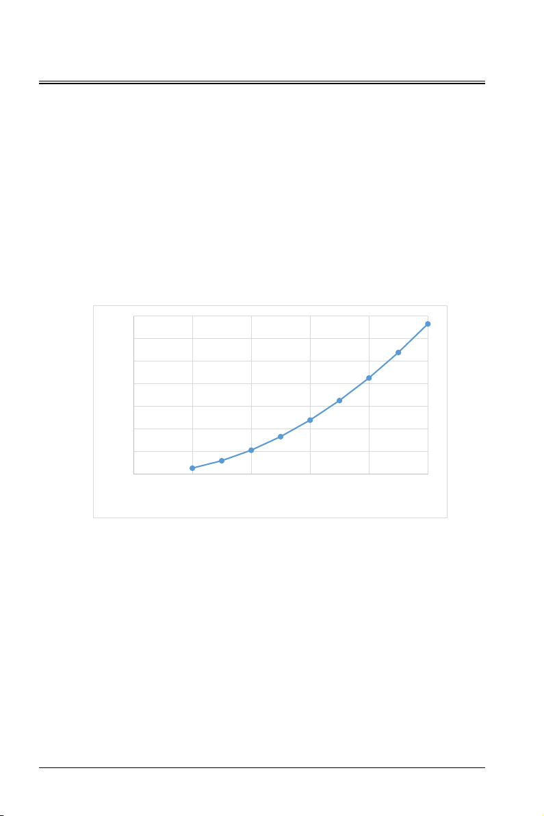
High Brightness precautions: Hazard Distance (HD)
HD
Hazard Distance(HD)is the distance measured from the projection lens as at which the intensity or the energy
per surface unit becomes lower than the applicable exposure limit on the cornea or on the skin. The light
beam is considered (to be) unsafe for exposure if the distance from a person to the light source is less than
the HD.
This projector can incorporates interchangeable projection lens and the risk group is determined with the
lens with throw radio more than 2.0 according to the standard IEC 62471-5:2015.
This projector may become RG3 when an interchangeable lens with throw ratio greater than 4.0 is installed.
Refer to the manual for the lens list and hazard distance before operation. Such combinations of projector
and lens are intended for professional use only, and are not intended for consumer use.
Warning: For RG3 projectors, no direct exposure to the beam shall be permitted and operators shall
control access to the beam within the hazard distance or install the product at a height that will prevent eye
exposure within the hazard distance.
7
6
5
4
3
2
Hazard distance (m)
1
0
0.0 2.0 4.0 6.0 8.0 10.0
Throw radio
8
Page 9
Important Safety Instructions
FCC Statement
This device complies with part 15 of the FCC Rules. Operation is subject to the following two conditions:
(1) This device may not cause harmful interference, and (2) this device must accept any interference received,
including interference that may cause undesired operation.
Warning: Changes or modifications to this unit not expressly approved by the party responsible for
compliance could void the user’s authority to operate the equipment.
NOTE: This equipment has been tested and found to comply with the limits for a Class A digital device,
pursuant to part 15 of the FCC Rules. These limits are designed to provide reasonable protection against
harmful interference when the equipment is operated in a commercial environment. This equipment
generates, uses, and can radiate radio frequency energy and, if not installed and used in accordance
with the instruction manual, may cause harmful interference to radio communications. Operation of this
equipment in a residential area is likely to cause harmful interference in which case the user will be required
to correct the interference at his own expense.
Shielded cables must be used with this unit to ensure compliance with the Class A FCC limits.
ETL Directive
CONFORMS TO UL STD. 60950-1
CERTIFIED TO CSA STD.C22.2 NO. 60950-1
9
Page 10

Important Safety Instructions
WEEE Directive
Correct Disposal of this product. This marking indicates that this product should not be disposed
with other household wastes throughout the EU. To prevent possible harm to the environment or
human health from uncontrolled waste disposal,recycle it responsibly to promote the sustainable
reuse of material resources. To return your used device, please use the return and collection
systems or contact the retailer where the product was purchased. They can take this product for
environmental safe recycling.
RoHS
According to the "electronic information products pollution control management approach", for controlling
and reducing the electronic information products that may cause environmental pollution after discard,
promote the production and sales of low-pollution electronic information products, to protect environment
and human health. The harmful substances that may be contained in this product are as follows:
Name and content of hazardous substances in the product
Harmful substances
Parts Name
Power cord
Internal power supply
Plastic enclosure
Light source assembly
Lens assembly
Optical receiver/transmitter assembly
Fan assembly
Speaker
Antenna assembly
PCB assembly
Other metal pieces
Remote control
This form is prepared in accordance with IEC62321.
: Indicates that the content of the hazardous substance in all homogeneous materials of the part is below
○
the limit specified in IEC62321.
×: Indicates that the content of the hazardous substance in at least one of the homogeneous materials of
the part exceeds the limit specified in IEC62321.
Note: Partial components marked with × contains more harmful substances due to limited industry
technology level and are temporarily unable to achieve the replacement or reduction.
Pb Hg Cd
○ ○ ○ ○ ○ ○
× ○ ○ ○ ○ ○
○ ○ ○ ○ ○ ○
× ○ ○ ○ ○ ○
○ ○ ○ ○ ○ ○
○ ○ ○ ○ ○ ○
○ ○ ○ ○ ○ ○
○ ○ ○ ○ ○ ○
○ ○ ○ ○ ○ ○
× ○ ○ ○ ○ ○
○ ○ ○ ○ ○ ○
× ○ ○ ○ ○ ○
Hexavalent
chromium
Cr (VI)
Polybrominated
biphenyls
PBB
Polybrominated
diphenyl ethers
PBDE
Caution
The projector products comply with the EU RoHS directive (restrictions on the use of certain hazardous
substances directive in electrical and electronic equipment). All parts marked with × are exception parts
permitted by EU RoHS instructions.
10
Page 11
Overview
About This Manual
Repair: Only trained and qualified service technicians (understand laser safety, UV radiation, high voltage and
connected circuits that create all the potential hazards) can open the projector for repair.
Disclaimer: Appotronics Corporation has endeavored to ensure the accuracy and reliability of the information
provided in this document. However, as the product continues to improve, the information in this document
is subject to change without notice. Appotronics Corporation is not responsible for omissions or inaccurate
information. The updated version of this document is issued on a regular basis as needed. Please contact
Appotronics Corporation to obtain the latest version.
Safety Warnings and Guides
Labels and Tags
Observe and follow all warnings and instructions marked on the projector.
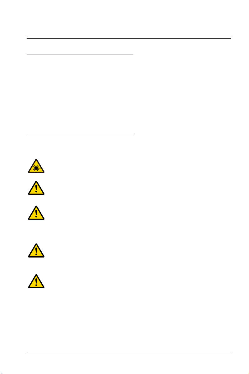
Class 1 laser product, IEC 60825-1:2014
As with any bright source, do not stare into the direct beam, RG2 IEC 62471-5:2015.
Caution: Use of controls or adjustments or performance of procedures other than those
specified herein may result in hazardous radiation exposure.
Laser-illuminated projectors – although generally Class 1 laser products during operation –
usually contain Class 4 embedded lasers. Service shall be performed only by authorized, trained
servicing personnel (IEC 60825-1).
General Warning Information
This symbol alerts users to notice important information about the operation and maintenance.
Please read this information carefully to avoid problems.
The projectors shall be installed above the reach of children.
Caution: Never allow supervise children to stare into the projector beam at any distance from the
projector.
Caution: Do not stare into the projector beam when using the remote control for starting the
projector while in front of the projection lens.
Caution: Avoid the use of optical aids such as binoculars or telescopes inside the beam.
11
Page 12
Overview
Installation Requirements
Environment conditions
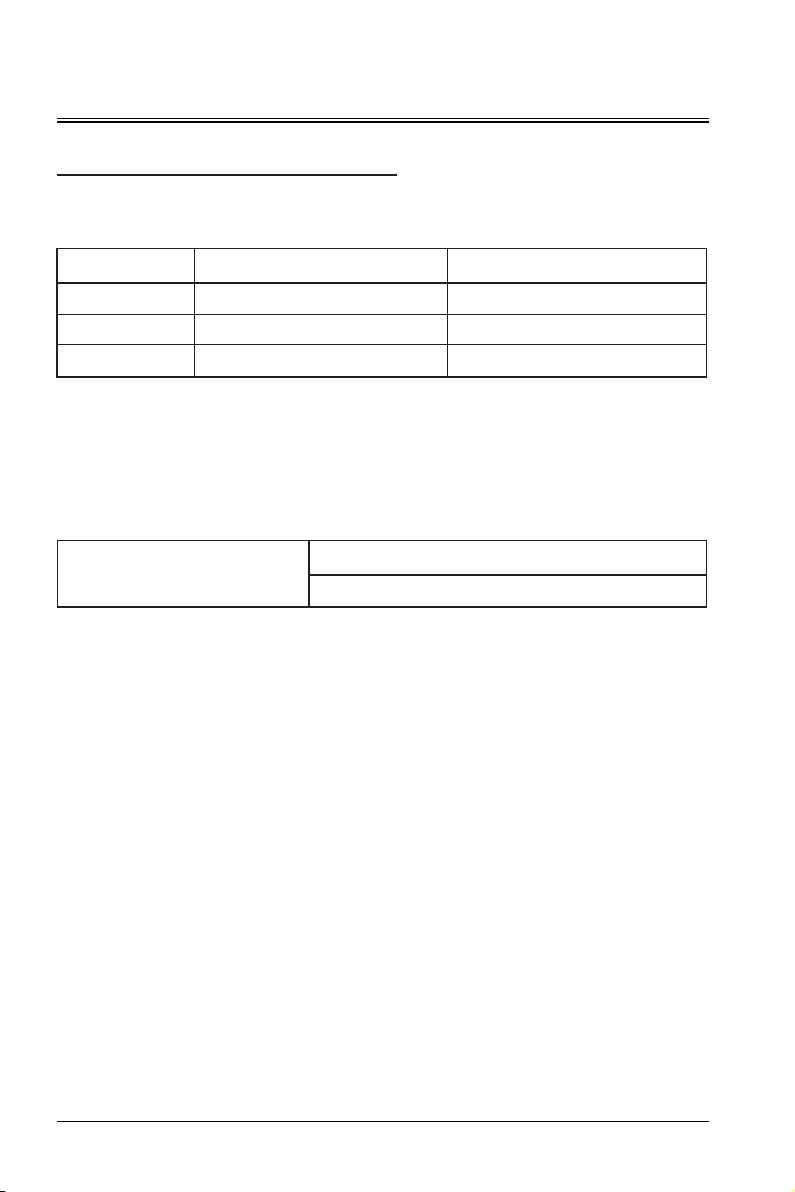
The following table describes the physical environment for safe operation or storage of the projector.
Environment Operation Storage
Ambient temperature 0ºC-40ºC (*1) -10ºC-60ºC
Humidity 10%-90% RH (non-condensing) 10%-90% RH (non-condensing)
Altitude 0-2000 m (*2) 0-2000 m
(*1): Derated use at 35ºC-40ºC
(*2): Below 2000 m for 3C certification
Main power requirements
The Appotronics engineering projector adopts the nominal single-phase power supply (with dedicated
grounding PE).
Projector
This projector comes with a power cable used to connect to the projector and the power supply.
Projector weight
Do not underestimate the weight of this projector. The projector weighs about 29 kg. Ensure that the base or
hoisting frame used to install the projector can withstand five times the entire load of the system.
Power Supply Requirements
AC 100-240 V, 10A,50/60 Hz
12
Page 13

Overview
extension cable
Packaging Overview
This product is delivered with all the items shown below. Check the packaging to ensure that the items are
complete. If any items are missing, please contact the dealer immediately.
ID SET
Lens
2 3
1
4 5 6
7 8 9
0
Source
HDbaseT DVI
HDMI
RGB1 VideoOKRGB2 DP
Projector Power cable HDMI cable Remote control
User Manual CD-ROM Quick Start Guide
Infrared receiver
Caution
- Because of the differences in the application in each country (region), the products delivered to some
regions may come with different accessories.
13
Page 14
Overview
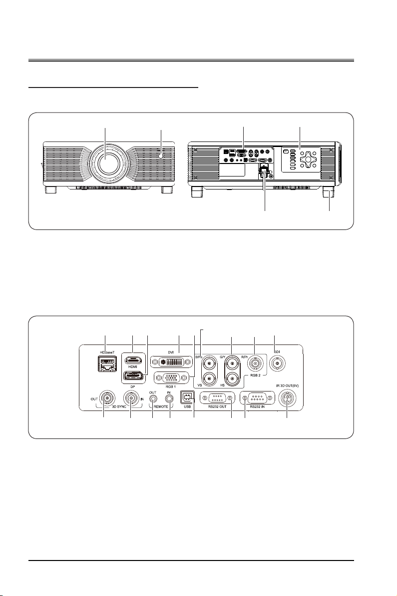
Projector Appearance
Main unit
Infrared receiver (front)
①
Projection lens
②
Control panel
③
Input and output panel
④
I/O panel
①
①②
③② ④ ⑥ ⑨⑦
④
⑤ ⑥
Power port
⑤
Adjustment feet
⑥
⑧
③
HDBaseT port
①
HDMI port
②
DP port
③
DVI port
④
RGB1 IN port
⑤
14
⑩⑤⑪ ⑫ ⑬ ⑭ ⑮ ⑯ ⑰
B/Pb VS port
⑥
G/Y HS port
⑦
R/Pr port
⑧
SDI port
⑨
3D SYNC OUT port
⑩
3D SYNC IN port
⑪
REMOTE OUT port
⑫
REMOTE IN port
⑬
USB port
⑭
RS232 OUT port
⑮
RS232 IN port
⑯
IR 3D OUT port
⑰
Page 15
Overview
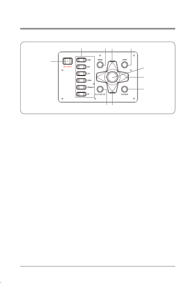
Control panel
③
②
⑥⑤
①
④
②
⑦
⑧
②
Power button (power-on/off)
①
Press the power button to enable the projector. In the power-on state, press the power button twice to
power off the projector.
Arrow key
②
Scroll up and down on the menu; select from the left or decrease the value, or select from the right or
increase the value.
Signal source
③
RGB, SDI, DVI, HDMI, HDBaseT, and DP from top to bottom.
Note: RGB1 and RGB2 is enabled in turn when pressing the RGB button.
OK button
④
Press to select or confirm the current value or item.
Menu button
⑤
Press the menu button to display the screen menu. Press the menu button again to go back to the previous
menu or exit the screen menu.
Lens adjustment button
⑥
Press to call/switch to the lens adjustment menu. The functions include zooming, shifting, and focusing.
Douser button
⑦
When an image is displayed, press to disable the display, and press again to enable the display.
Automatic settings
⑧
Press to enter the automatic lens centering adjustment.
15
Page 16
Overview
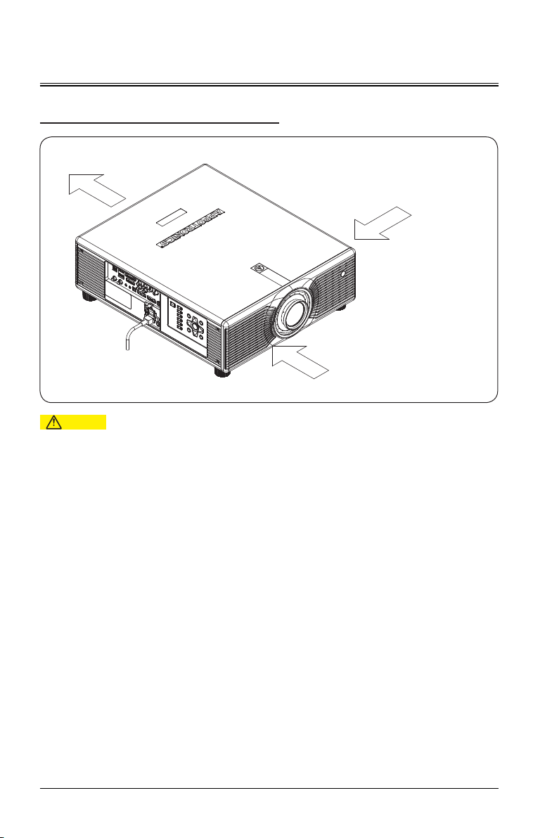
Air Duct Direction
air outlet direction
air inlet direction
air inlet direction
Caution
The heat dissipation and exhaust air volume of the projector is 360CFM. If you need to install a fan
-
around the projector, please install the fan on the side of the air inlet direction.
16
Page 17

Overview
Remote Control
Lens
Shift
0
OK
Source
ID SET
Zoom
Image
Return
Douser
RGB2 DP
①
②
Focus
1 2 3
③
4 5 6
7 8 9
④
⑤
Pattern
Menu
⑥
⑦
Blank
HDMI
HDBaseT DVI
⑧
RGB1 Video
Caution
The operating angle of the remote control
-
should be within plus or minus 30°.
The Video button corresponds to the
-
projector SDI signal.
Power button
①
In standby mode, if you press this key, the device
is powered on; in power-on mode, if you press
this key, the screen prompts for the power-off
operation. Press the power button to shut down
⑨
the device.
Lens
②
Press Focus,Shift or Zoom button repeatedly to
enter the lens focusing, shifting or zooming menu.
1/2/3/4/5/6/7/8/9/0 (number key)
③
Press to enter the corresponding number.
Pattern
④
Press repeatedly to display internal test pictures
in a cycle manner.
Menu
⑤
Press to display the main menu. If you press
the key again, the main menu disappears or the
⑩
system returns to the previous-layer menu.
(Arrow key)
⑥
⑪
Scroll up or down to select the adjustment item;
move to the left to select an adjustment item or
⑫
decrease the value; move to the right to select an
adjustment item or increase the value.
Blank
⑦
Press to switch the picture to the blank screen.
Source
⑧
⑬
Set the input source to HDMI, HDBaseT, DVI,
RGB1, SDI, RGB2 or DP.
ID SET
⑨
When multiple channels are spliced, set the ID
number of each remote receiver.
Image
⑩
Press to switch image modes among standard,
DICOM, picture, cinema, bright, REC709, video
and user.
Return
⑪
Press to exit the settings.
OK
⑫
Press to select or confirm the current value or
item.
Douser
⑬
When an picture is displayed, press to disable the
display, and press again to enable the display.
17
Page 18
Overview
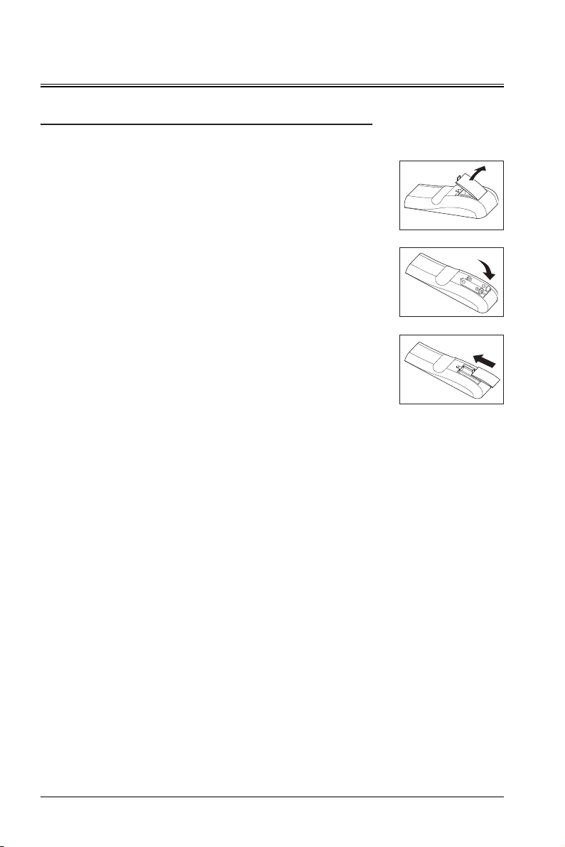
Replacing the Battery of the Remote Control
Procedure
Place the remote control with the back facing up,
and open the battery cover.
①
Put the new battery to the battery compartment.
Ensure that the polarity (+ and -) of two AAA
batteries are correctly connected to the
connectors in the battery compartment.
Install the battery cover.
Precautions for the remote control
Ensure that the polarity is correct when inserting the battery.
Do not throw the battery into the fire, since there may be a risk of explosion.
If the remote control is not used for a long period of time, remove the battery to avoid leakage and
damage to the remote control.
The liquid in the battery is harmful to the skin. Do not let the hands directly contact the liquid. When
installing a new battery, clean the leaked liquid thoroughly.
In most cases, you only need to point the remote control to the screen. The infrared signals will be
reflected back from the screen and received by the infrared sensor on the projector. However, in certain
circumstances, the projector may fail to receive signals from the remote control due to environmental
factors. In this case, point the remote control to the projector and try again.
If the effective signal receive range of the remote control is short, or the remote control does not work,
replace the battery.
If the infrared receiver is exposed to fluorescent or strong sunlight, the remote control may not work
properly.
Please refer to requirements for handling waste batteries of the local government. Improper handling of
waste batteries will cause damage to the environment.
②
③
18
Page 19
Installation
Replacing the Lens
Before replacing the lens, shut down the projector and remove the power cable from the socket.
Before replacing the lends, adjust the lens position to the center. If the lens is not in the center,
replacement may fail.
When moving the lens, do not stuck the lens at the lens opening.
The projector and the lens are precision instrument parts. Do not vibrate them or use brute force.
When replacing the lens, do not touch the lens surface.
Do not leave dust or grease on the lens surface, nor scratch the lens surface.
Do not replace the lens in a dusty room. Dust inside the projector will cause picture quality degradation.
Do not separate the lens and projector for a long time. Dust inside the projector will cause picture quality
degradation.
Do not touch the signal contact of the lens. When the dust is adhered to the lens, it may cause contact
failure.
Do not transport the projector with an optional lens. Otherwise, the projector may be damaged.
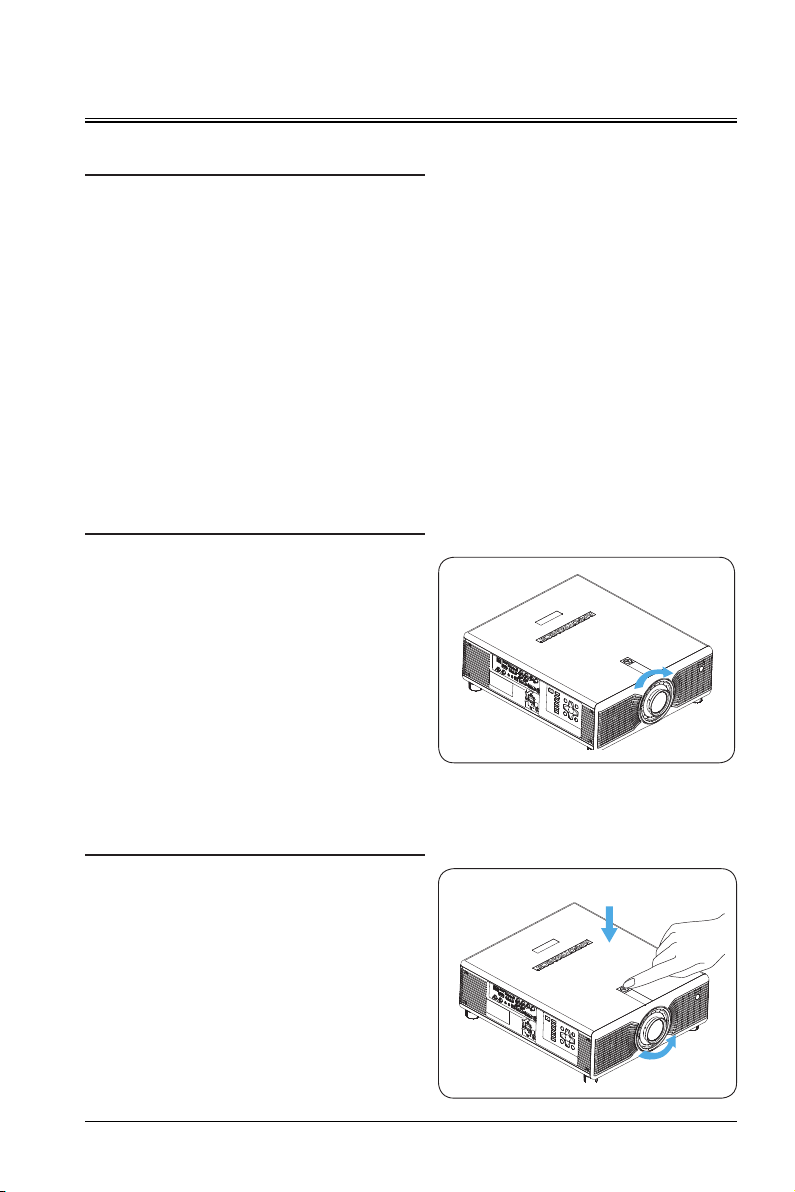
Installing the Lens
Align the lens structure to lock the lens.
Rotate the lens clockwise until you hear a "click"
sound, indicating that the lens is aligned.
At this time, the lens is installed.
Removing the Lens
Before replacing the lens, adjust the lens to the
center.
As shown in the figure, press the lens lock
switch on the top cover, and rotate the lens
counterclockwise for about 30°.
Hold the lens, and move forward to take out the
lens.
19
Page 20
Installation
①
④② ③
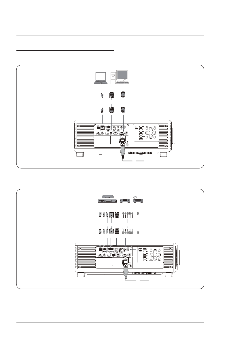
Connecting to the Projector
Connect the projector to the PC or laptop computer.
Power cable
①
HDMI cable
②
VGA cable
③
RS232 cable
④
Connecting to the video device
Power cable
①
HDMI cable
②
VGA cable
③
DVI cable
④
HDBaseT cable
⑤
-⑥ DP cable
5BNC cable
⑦
SDI cable
⑧
②
⑥ ③④ ⑦ ⑧⑤
Connecting to the socket
20
Connecting to the socket
①
Page 21

Installation
Powering on/Power off
Powering on
Ensure that the power cable and signal cable are securely connected. Turn on the power switch and wait
until the state LED indicator is steady on red.
Press the power button on the remote control or control panel to start up the projector. The state LED
indicator is on green, and the screen displays "No signal".
Enable the signal source. Select the signal source (HDMI, HDBaseT, DVI, RGB1, Video, RGB2, or DP)
using the remote control or button. The projector detects the input source and displays pictures.
Front infrared
receiver
POWER button
POWER buttonPOWER button
ID SET
Lens
Focus
Shift
1 2 3
4 5 6
Zoom
Powering off
Press the power button on the remote control or control panel to shut down the projector.
Caution
- Do not power on the project immediately after it enters the standby mode.
21
Page 22
Installation
H H
V
V
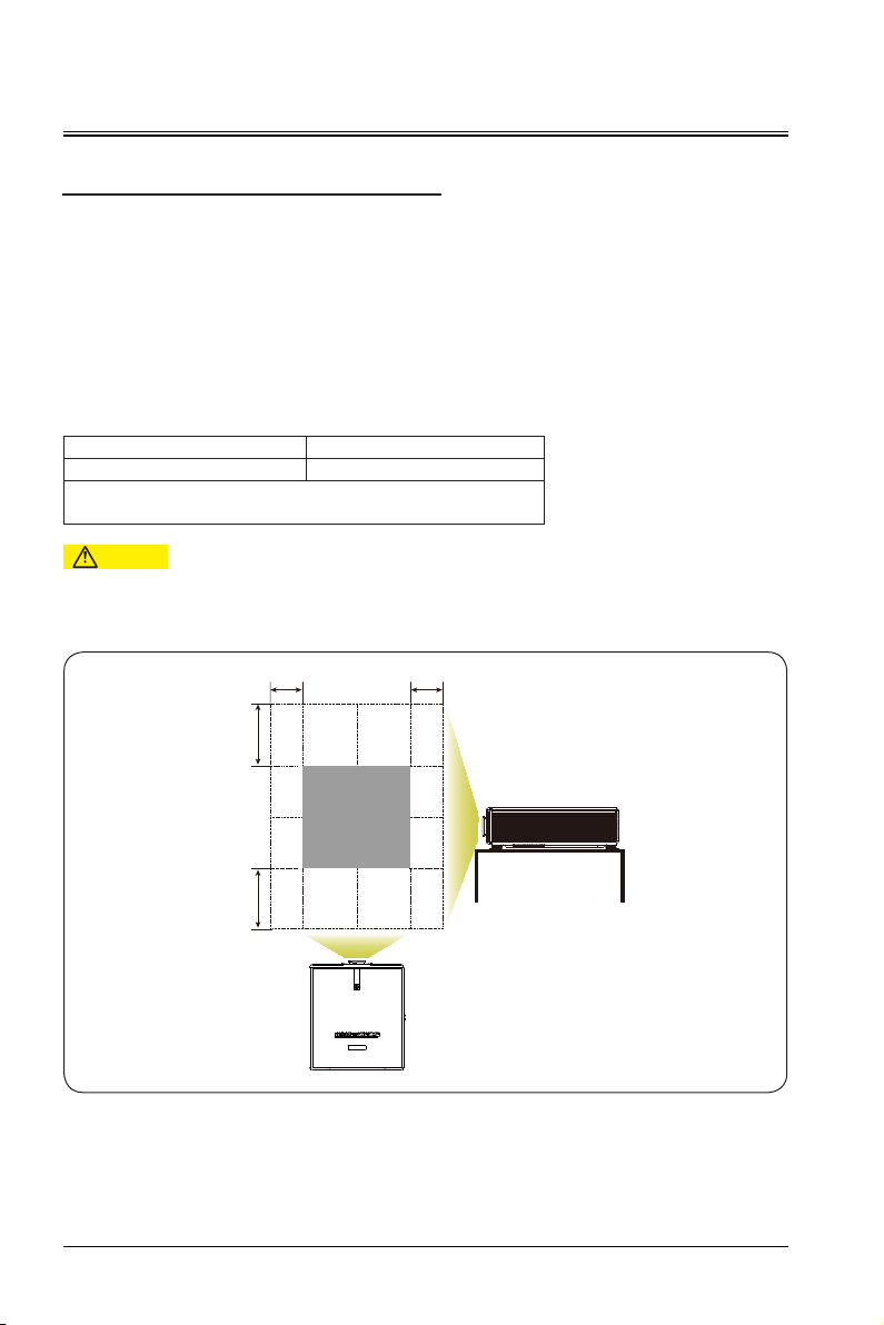
Adjusting the Projected Image
Adjusting the projector position
To determine the position where the projector is placed, consider the size and shape of the screen, the
location of the power outlet, and the distance between the projector and other devices. The following are
general principles:
Place the projector on a flat surface and keep a correct angle with the screen.
Place the projector at an ideal location from the screen.
The distance from the projector lens to the screen, the zoom settings, and the video format determine the
size of the projected picture.
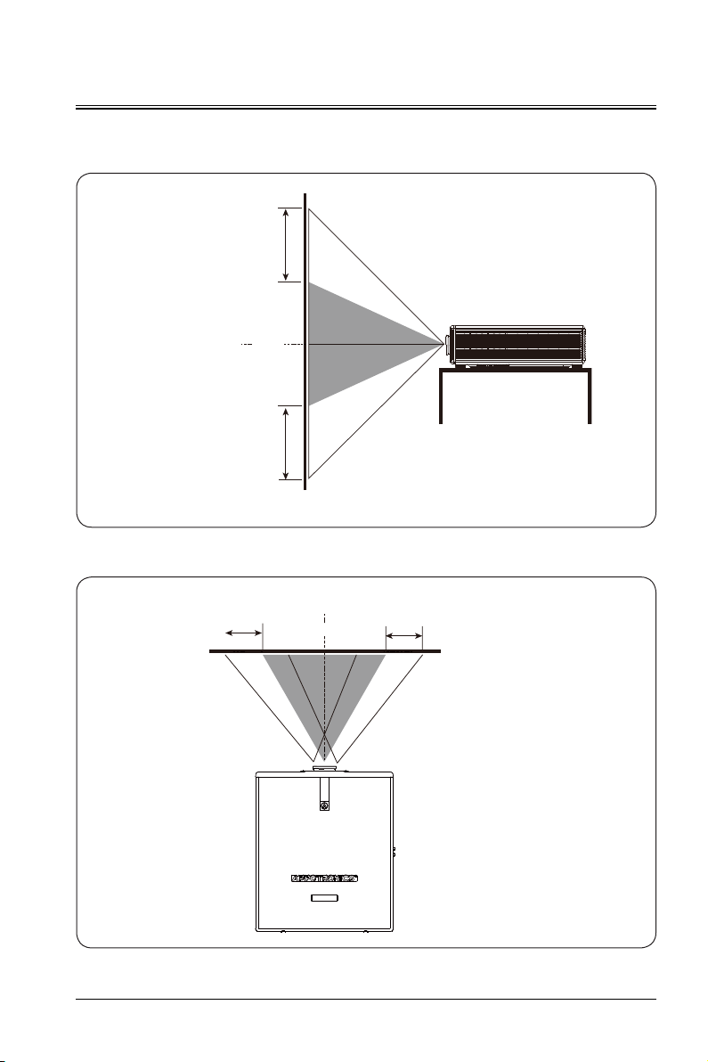
For the picture offset (shift) range of this projector, see the following table:
H V
H: Horizontal offset range of the picture when the lens is centered.
V: Vertical offset range of the picture when the lens is centered.
- The values in the table above are approximate and may differ slightly from the actual values. The actual
values shall apply.
±20% ±55%
Caution
22
Page 23
Installation
Schematic diagram of vertical offset when the lens is centered
The above table describes the vertical offset ranges when the lens in different models.
+55%
Lens center
100%
-55%
Projector screen
Schematic diagram of horizontal offset when the lens is centered
Lens center
-20% +20%
100%
100%
Projector screen
23
Page 24
Installation
Ceiling-mounted Installation
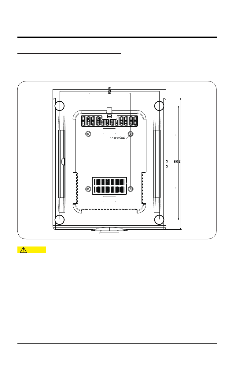
Ensure that the screws used secure the mounting bracket meet the following specifications:
Screw type: It is recommended to use M8*16 screws.
Assembly size: see the figure below.
Caution
- If the projector is damaged due to improper installation, the warranty becomes invalid.
24
Page 25
User Menu Control
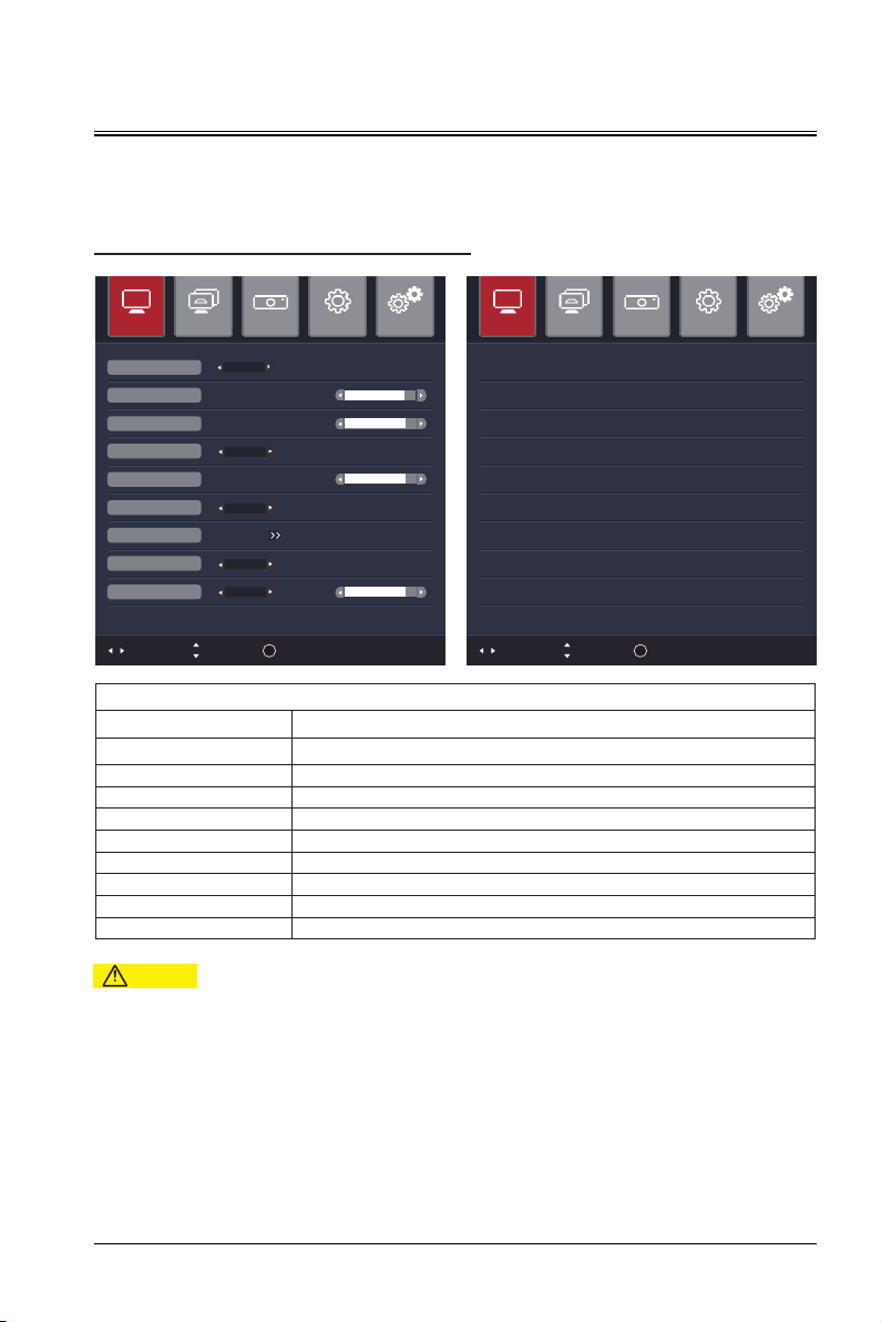
Sub-menu: Picture, Graph, Project, Settings, and Advance. You can move the cursor among these options.
The menu supports automatic preview of sub-menus.
IMAGE
Image Graph Project Settings Advance
Move
Standard
Standard
6500K
0
0
0
Off
Off
On
0
OK
Enter
Picture Mode
Brightness
Contrast
Gamma Set
Sharpness
Color Temp.
Color Settings
DNR
MPEG NR
Bri.Color
Adjust
Image Graph Project Settings Advance
Hue
Saturation Gain White
R-H: 0 0R-S: 0 R-G: 0 R-W:
G-H: 0 0G-S: 0 G-G: 0 G-W:
B-H: 0 0B-S: 0 B-G: 0 B-W:
C-H: 0 C-S: 0 C-G: 0
M-H: 0 M-H: 0 M-G: 0
Y-H: 0 Y-H: 0 Y-G: 0
Move
OK
Adjust
Enter
Image
Function Attribute Value
Picture Mode Bright, Standard, DICOM, Image, Cinema, Bright, REC709 and Video
Brightness 0-100
Contrast 0-100
Gamma Set Brightness, Standard, Linear, RGB, Film, Bright, Photo, Video
Sharpness 0-24
Color Temp. 6500K, 7500K, 9300K and User
Color Settings Hue, Saturation, Gain and White
DNR Off, Low, Mid, High, Ultrahigh
MPEG NR On, Off
Caution
- Picture Mode is related to Gamma Set, Color Settings, Bri.Color function.
25
Page 26

User Menu Control
Aspect Ratio
Freeze
Test Patt.
Ver keystone
RGB Advance
Adjust
Move
Enter
0
Full
Off
Off
OK
Auto Adjust
Horizontal Position
Vertical Position
Phase
Adjust
Move
Enter
Clock
0
0
0
0
OK
Image Graph Project Settings Advance Image Graph Project Settings Advance
GRAPH
Function Attribute Value
Graph
Aspect Ratio Native, 4:3, 16:9 and Full
Freeze On, Off
OFF, White, Black, 100% Red, 100% Green, 100% Blue, 100% Cyan,
Test Patt.
100% Magenta, 100% Yellow, Color Bar, Gray, Check Boarder, Grid,
BGRW Ramp
Ver Keystone ±40
RGB Advance Auto Adjust, Horizontal Position, Vertical Position, Phase, Clock
Caution
- The aspect ratio "Native" will set the corresponding mode according to the aspect ratio of the input signal.
- RGB channel signal in RGB advanced settings
- ">>": Enter the sub-menu.
26
Page 27
User Menu Control
Projection
Operation Mode
3D Setting
Blank Screen
Adjust
Move
Enter
Input Source
Lens Auto Center
Lens Adjust
Table Front
Std 100%
Off
Black
OK
Image Graph Project Settings Advance
3D FORMAT OFF
3D DISPLAY DLP LINK
L/R EYE FLIP
>
3D SETTING
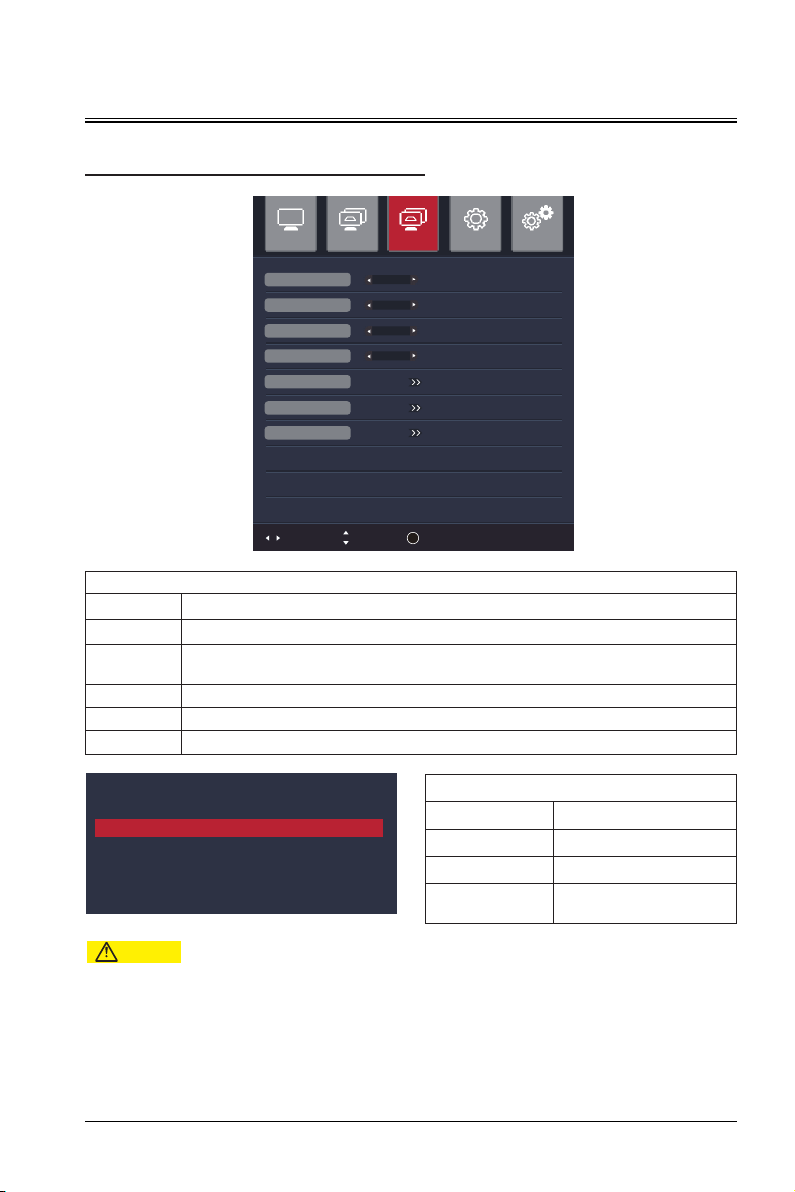
PROJECT
Project
Function Attribute Value
Projection Table Front , Table Rear, Ceiling Front and Ceiling Rear
Operation
Mode
3D Setting Off, Frame mode, Top by bottom and Side by side
Blank Screen White, Red, Green, Blue, Cyan, Magenta, Yellow and Black
Input Source HDMI, DVI, DP, HDBaseT, RGB1, RGB2/YUV, and CVBS
Std 100%, ECO 30% and ECO 50%
Caution
- The lens is automatically centered based on the voltage fed back by the sensor.
3D Setting
Function Attribute Value
3D FORMAT ON, OFF
3D DISPLAY DLP LINK, Infrared
L/R EYE FLIP
Press OK to swap between
left and right eye.
27
Page 28
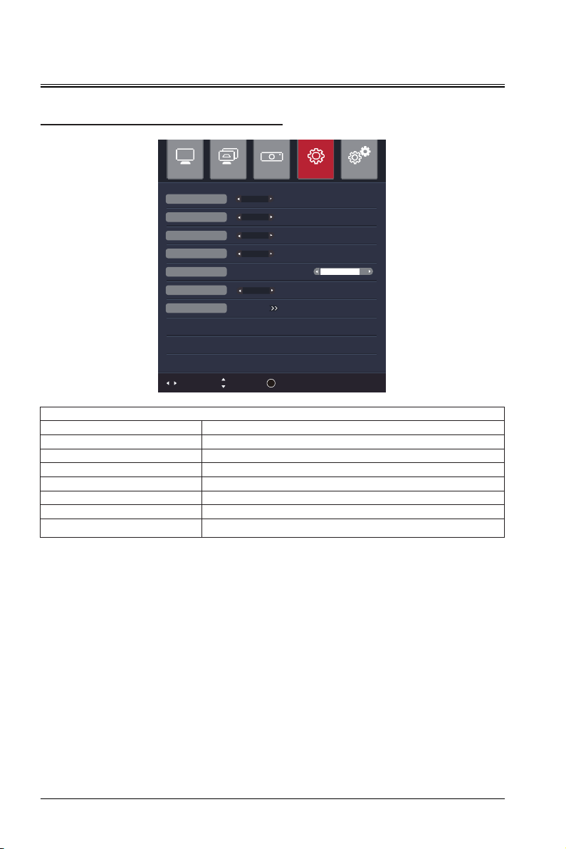
User Menu Control
SETTINGS
Image Graph Project Settings Advance
Language
High Altitude Mode
OSD Position
OSD Rotation
OSD Transparency
Logo Set
Factory Reset
System Infor Package: Usage Time: 0 Hour s
Adjust
English
Off
Centre
Off
0
On
Source: HDMI No Signal
Move
OK
Enter
Settings
Function Attribute Value
Language Chinese and English
High Altitude Mode On, Off
OSD Position Center, Left-Top, Right-Top, Left-Below and Right-Below
OSD Rotation 90, 180, 270, and Off
OSD Transparency 0-5
Logo Set On, Off
Factory Reset Enter the sub-menu and select to reset the settings.
28
Page 29
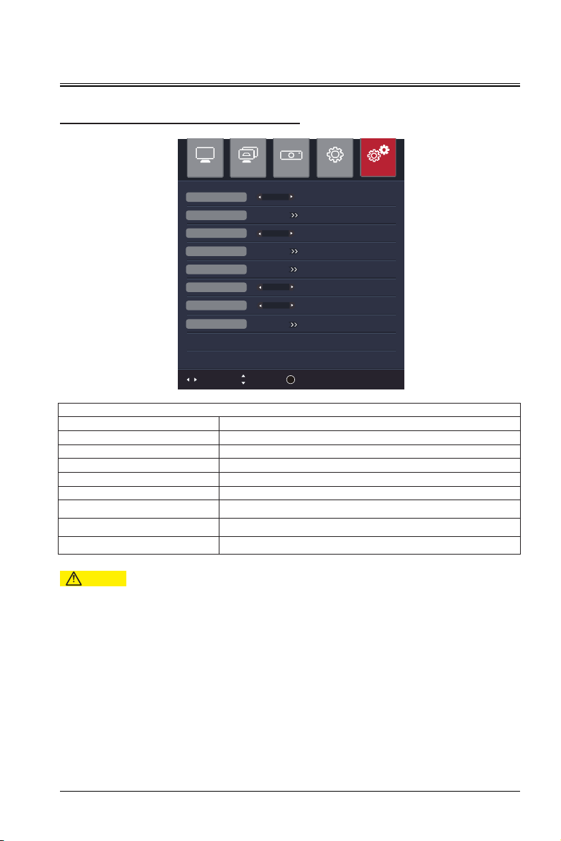
User Menu Control
Edge Blending
Edge Fuse
Geometric/consis
Geometric corr set
Sharp Mode
Dynamic Contrast
Unit Settings
Adjust
Move
Enter
Umiformity Set
Off
Off
Off
OK
Off
Image Graph Project Settings Advance
ADVANCE
Function Attribute Value
Edge Blending Off, On, On+menu
Edge Fuse >>
Geometric/consis On, Off
Uniformity Set >>
Geometric corr set >>
Sharp Mode On, Off
Dynamic Contrast On, Off, Advance
Unit Settings >>
Caution
- When the sharp mode is enabled, the sharpness of the picture is raised to the highest level.
Advance
29
Page 30
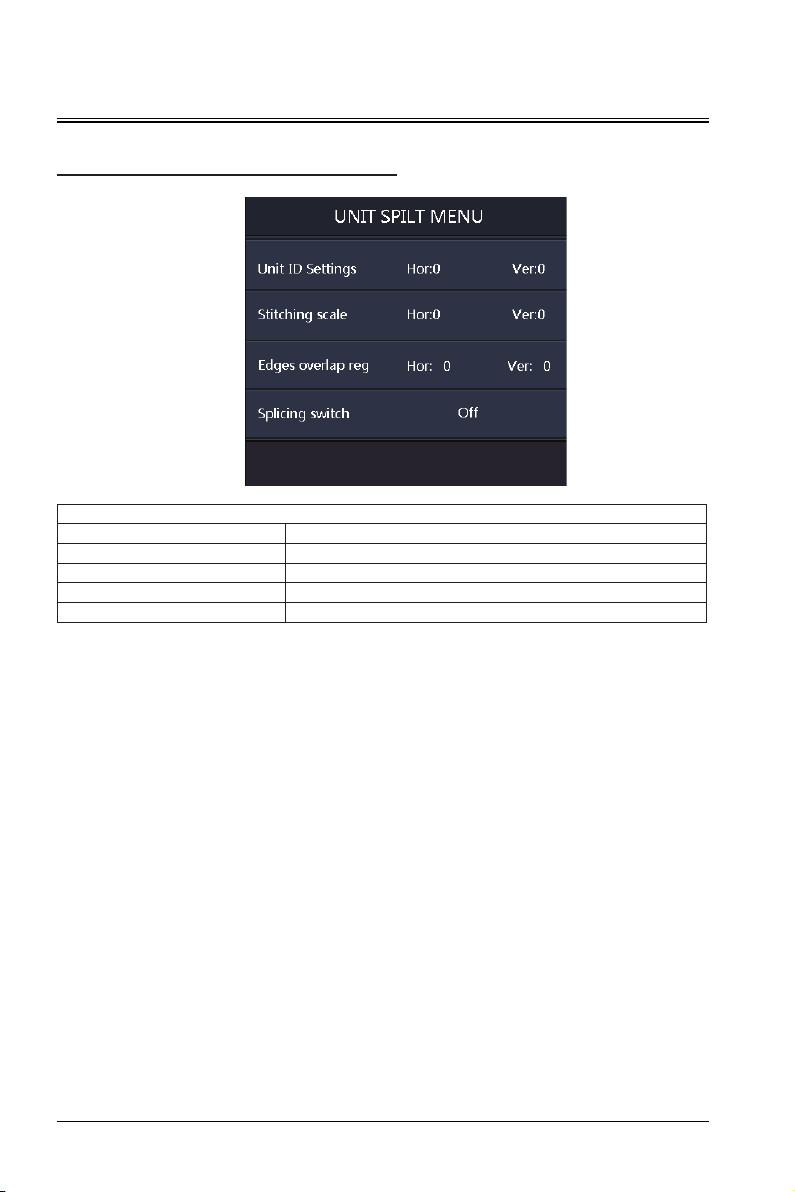
User Menu Control
UNIT SPILT MENU
Function Attribute Value
Unit ID Settings Horizontal Position: 1-15; Vertical Position: 1-15
Stitching scale Horizontal Position: 1-15; Vertical Position: 1-15
Edges overlap reg Size: 0-400
Splicing switch On, Off
UNIT SPILT MENU
30
Page 31
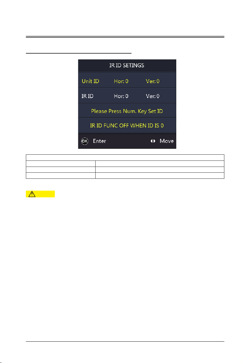
User Menu Control
IR ID SETTINGS
Function Attribute Value
Unit ID Horizontal Position: 1-15; Vertical Position: 1-15
IR ID Horizontal Position: 1-15; Vertical Position: 1-15
Caution
- On the advanced screen, select remote control ID to enter the level-2 menu, as shown in the above figure.
IR ID SETTINGS
31
Page 32

User Menu Control
Lens Position Adjustment
Function Attribute Value
Lens Position Adjustment Top, Below, Left, Right
Lens Zoom Adjustment Top, Below
Lens Focus Adjustment Top, Below
Caution
- On the projection screen, select lens adjustment to enter the level-2 menu, as shown in the above figure.
32
Lens Position Adjustment
Page 33

User Menu Control
Consistency Adjustment/Geometric Correction
Function Attribute Value
Consistency adjustment
Function Attribute Value
Geometric correction
Consistency adjustment
Press the OK button to switch between the adjustment and moving
functions. Press the up, down, left and right buttons to select a point.
In the adjustment mode, adjust the RGBW parameters using the left
and right buttons, or switch between the gain and compensation
functions using the up and down buttons.
Geometric correction
Press the OK button to switch between the adjustment and moving
functions; press the Up, Down, Left, and Right buttons to adjust or
move.
Caution
- On the advanced screen, select geometry correction to enter the level-2 menu, as shown in the above
figure.
33
Page 34

User Menu Control
Edge Blending
Geometric/consis
Geometric corr set
Sharp Mode
Dynamic Contrast
Unit Settings
Adjust
Move
Enter
Umiformity Set
Off
Off
Off
Off
OK
Edge Fuse
Image Graph Project Settings Advance
Edge Blending Adjustment
Edge blending adjustment
Function Attribute Value
Press the OK button to switch between the adjustment and moving
Edge Blending
Fine Adjustment
functions; press the Up, Down, Left, and Right buttons to adjust or
move.
Through fine adjustment, the product function can be closer to the
subjective desire of the controller.
Caution
- On the advanced screen, select edge merging to enter the level-2 menu and enable the edge merging
function. According to the location of the device, set the size of the merging area, making the device
merging area and displayed overlapping area exactly the same, so that the entire cropping screen is
integrated as a whole.
34
Page 35
Fault Handling
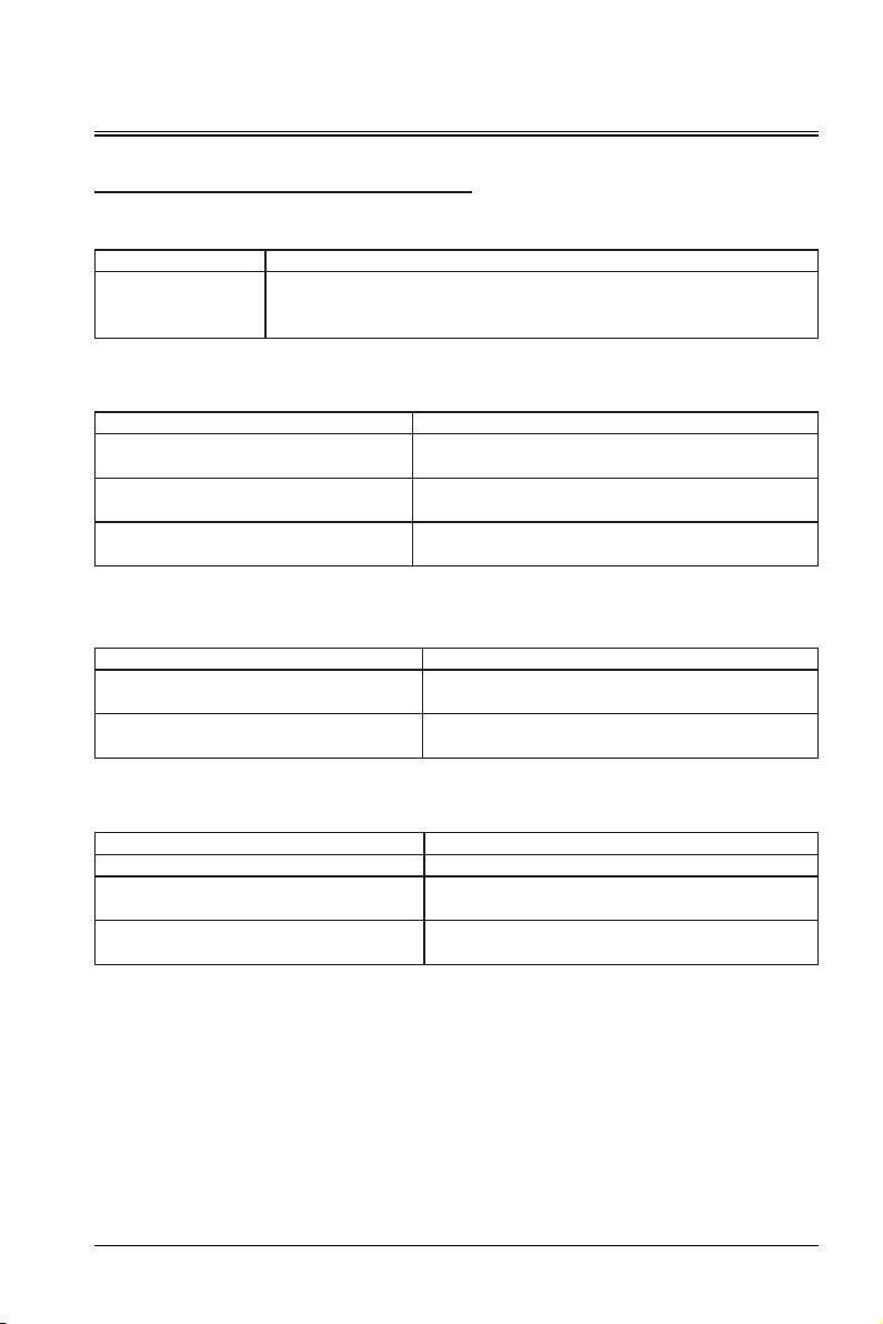
Troubleshooting
The projector fails to power on.
Cause Solution
The power cable
supplies no power.
No picture
The video signal source is not enabled or is
incorrectly connected.
The projector and the input signal device are
not properly connected.
The input signal is not correctly selected.
The picture is fuzzy.
Insert one end of the power cable to the AC port on the projector, and insert the
other end to the electrical outlet. If the electrical outlet has a switch, ensure that
the switch is turned on.
Cause Solution
Enable the video signal source and check whether the
signal cable is properly connected.
Check the connection.
Select the correct input signal source using the signal
source key on the remote control or control panel.
The lens of the projector cannot accurately
focus.
The projector does not accurately align with the
screen.
The remote control fails.
The battery level is low. Replace the battery.
There are obstacles between the remote control
and the projector.
The distance to the projector is too far.
Cause Solution
Adjust the focus of the lens using the focusing ring.
Adjust the projection angle and direction. If necessary,
adjust the projector's height or distance.
Cause Solution
Move the obstacles.
The distance to the projector should be no longer than 8
m (26 inches).
35
Page 36
Fault Handling
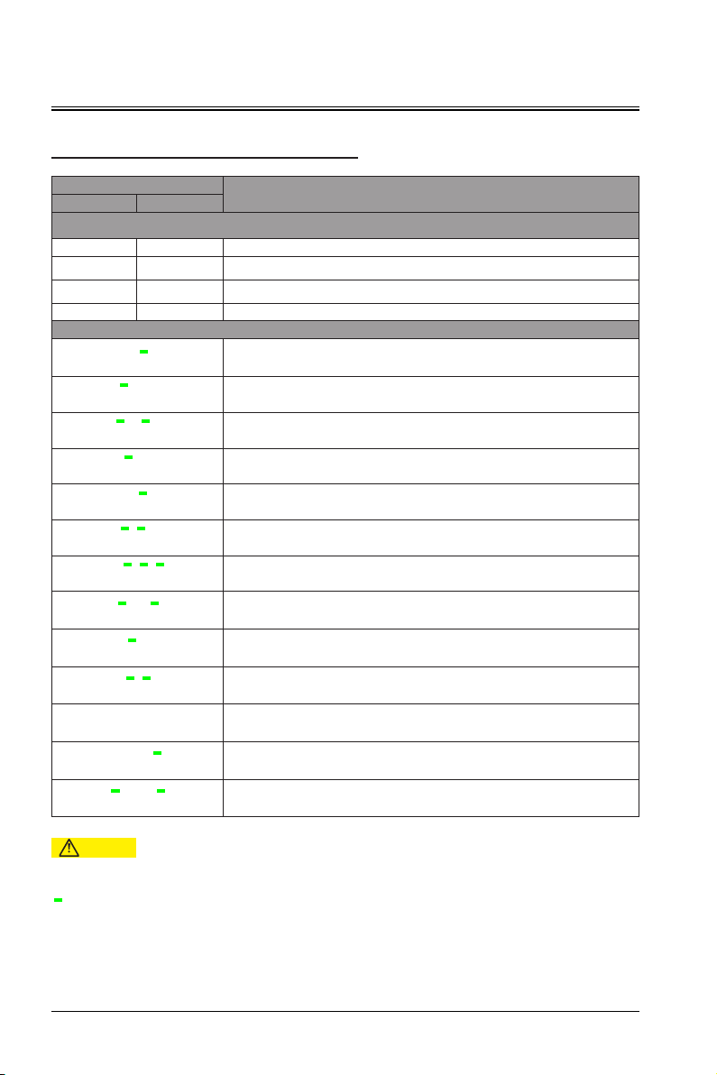
Indicator
Light
Red Green
Status
Course light
Off Off Power-off
On Off Standby mode
Off On Power-on state
Blinking Blinking Protection state upon running anomalies
System protection
●
(SN 1)
﹣
(SN 2)
●
﹣
(SN 3)
﹣
(SN 4)
● ●
(SN 6)
﹣ ﹣
(SN 7)
●
﹣ ﹣
(SN 10)
﹣
(SN 11)
●
﹣
(SN 12)
●
﹣ ﹣ ●
(SN 13)
● ● ●
(SN 14)
● ● ●
(SN 15)
● ●
﹣
(SN 16)
﹣
● ● ●
﹣
● ●
﹣
●
● ●
●
●
●
﹣
﹣
﹣
﹣
Color wheel failed to be enabled
DMD failed to be enabled
Light source failed to be enabled
Abonormal signal communication of main board
Temperature anomaly detection for the light source
Ambient temperature anomaly detection
DMD temperature anomaly detection
Temperature anomaly detection for the color wheel
Fan state anomaly detection
DID synchronization anomaly
DDP synchronization anomaly
Power temperature alarm
DLP anomaly
Caution
●
: Red indicator short blinking -- red indicator on for 0.5s (+ red indicator off for 0.5s).
: Green indicator long blinking -- green indicator on for 1.5s (+ green indicator off for 0.5s).
﹣
The error code sequence is displayed every 3s in a cycle manner.
36
Page 37
Maintenance and Repair Services
Projector Maintenance
You need to regularly maintain the projector and clean the lens.
Do not disassemble any parts of the projector. To replace the parts, please contact the dealer.
Cleaning the Lens
You can clean the lens when you find that the lens surface is stained or dusty.
Use a compressed air tank to remove dust.
If there is dust or stain, gently wipe the lens surface using the lens paper or damp cloth with some
cleaning agent.
Caution
- Do not rub the lens with abrasive materials.
Cleaning the Projector Enclosure
To remove dirt or dust, wipe the enclosure with a soft, lint-free cloth.
To remove strong dirt or spots, wet the soft cloth using water and neutral pH detergent, and then wipe the
enclosure.
Caution
- Do not use wax, alcohol, benzene, thinner, or other chemical cleaners because these substances can
damage the enclosure.
Storing the Projector
If you need to store the projector for a long period of time, follow the instructions below:
Ensure that the temperature and humidity of the storage area are within the recommended range for the
projector.
Retract the adjustment feet.
Remove the battery from the remote control.
Use the projector's original packaging or equivalent material to package the projector.
Transporting the Projector
It is recommended to use the original packaging or equivalent material when transporting the projector.
37
Page 38
Device Dimensions
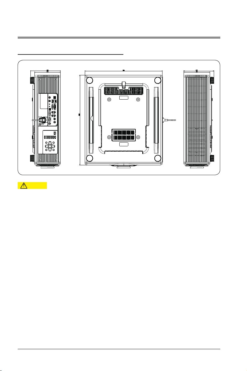
Projector Dimensions
Caution
- Be sure to use screws with the correct size. The length of the screw depends on the thickness of the
lifting plate.
- Be sure to leave a gap of at least 10 cm between the ceiling and the bottom of the projector.
- Do not install the projector near heat sources.
38
Page 39

Manufacturer: APPOTRONICS Co., Ltd
Address: 20F to 22F, High-Tech Zone Union Tower, No.63 Xuefu Road, Nanshan District, Shenzhen,
Guangdong, P. R. China
Website: www.appotronics.com
Importer: Appotronics USA Inc.
Address: 2828 North Harwood Street, Suite 1800 Dallas, TX 75201
Version: A
 Loading...