

Page 1
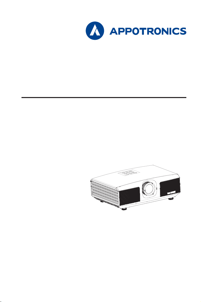
DLP PROJECTOR DISPLAY
User Manual
- Please read this manual carefully before using this equipment and keep it for future reference.
- Please read "Important Safety Instructions" carefully before using this product.
Page 2

Declaration
Copyright
Appotronics Corporation. All rights reserved. No part of this document may be reproduced, transmitted,
translated or stored in a retrieval system or translated into any text or computer language in any form or by
any means, including electronic, mechanical, magnetic, optical, chemical, handwritten or otherwise, without
the prior written permission of Appotronics Corporation.
All trademarks and registered trademarks are the property of their respective owners.
Disclaimer
Appotronics Corporation does not make any express or implied representations or warranties with respect
to any of the contents of this manual, and does not provide any warranties with respect to merchantability
or fitness for a particular purpose. In addition, Appotronics Corporation reserves the right to revise this
publication and to modify the contents of this document at any time without notice to anyone.
Warranty
Under normal use and storage conditions, Appotronics Corporation provides warranty on any materials and
process defects of this product. Proof of purchase date must be provided when you require the warranty
service. If the product is found to be defective during the warranty period, the sole obligation of Appotronics
Corporation and the exclusive remedy are to replace any defective parts (including labor service). When you
find the product is defective, immediately notify the dealer to obtain the warranty service.
IMPORTANT: If the customer fails to use the product in accordance with the written instructions, the above
warranty will not apply. In particular, the ambient humidity must be between 10% and 90%, the temperature
is between 0ºC and 40ºC, and the altitude is below 2000 meters. Do not operate the projector in a dusty
environment.
For additional information, please visit www.appotronics.com.
2
Page 3

Contents
Declaration ............................................... 2
Contents ................................................... 3
Important Safety Instructions ................ 4
General Safety Instructions ...................4
Security Tips ........................................4
FCC Statement ....................................8
cTUVus ................................................8
Overview ................................................... 9
About This Manual ...............................9
Safety Warnings and Guides ................9
Projector Features ..............................10
Packaging Overview ...........................11
Projector Appearance.........................12
Remote Control ..................................14
Replacing the Battery of the Remote
Control ...............................................16
Lens shift ...........................................17
Installation .............................................. 18
Projection mode .................................18
Adjusting the Projected Picture ...........19
Device Connection ................................ 21
Connecting the Projector to the PC or
Laptop Computer ...............................21
Connecting to the Audio or Video
Device ................................................21
Connecting the Projector to the
Computer or Display ..........................22
Connecting the Projector to the
Video Source Device ..........................23
Connecting the Projector to the
Audio Source .....................................24
Connecting the HDMI Device .............24
Connecting to the Component
Video Device ......................................25
Connecting to the S-video Device ......25
Connecting to the Composite Video
Device ................................................25
Operation ............................................... 26
Powering On the Projector .................26
Menus ................................................26
DISPLAY ............................................27
PICTURE ............................................28
SOURCE ............................................29
SETUP ...............................................30
ADVANCE ..........................................32
ABOUT ..............................................33
Serial Port ............................................... 34
Serial Port ..........................................34
Communication device .......................34
Reference Command List ...................35
Maintenance .......................................... 36
Projector Maintenance .......................36
Troubleshooting ..................................... 37
Indicator .............................................38
3
Page 4

Important Safety Instructions
General Safety Instructions
Please read this manual carefully before using this equipment and keep it for future reference.
The device shall be installed, operated and maintained by a qualified professional authorized by the
company.
All warnings listed on this projector and listed in this manual should be observed.
Strictly observe all instructions on operations and usage.
Strictly observe all local installation standards.
Security Tips
This device complies with international safety standards IEC60950-1, EN60950-1, UL60950-1, CAN/CSA
C22.2 No.60950-1. These standards are safety standards for information technology equipment that are
subject to stringent requirements for the use of critical safety components, components, materials and
insulators in order to protect the user and operator from the following hazards:
- Electric shock
- Energy-related hazards
- Fire
- Heat-related hazards
- Mechanical hazards
- Radiation
- Chemical hazards
In addition, these standards also raise limitations in many ways, such as internal and external temperature
rise levels, radiation levels, mechanical stability and intensity, peripheral construction and fire protection
devices. Even if the normal operation of the equipment fails, the single-point fault simulation test can also
ensure that the device can use the fuse, thermal circuit breakers, overcurrent protection devices and similar
devices to provide adequate protection of the human body.
This manual is for authorized users only for professional purposes and these persons should be familiar with
the potential hazards that may arise from this product. Only qualified maintenance personnel who are familiar
with such hazards can open the product shell to perform maintenance operations.
Terms:
Maintenance personnel:
Refer to the professional personnel who may use the training and skills to avoid possible harms to
themselves or others when they are in the maintenance contact area or the device in the restricted
contact area has obvious dangers.
Users:
Refer to all persons except maintenance personnel.
4
Page 5

Important Safety Instructions
Preventing the risk of electric shock
The projector should use AC power. Make sure that the main voltage and capacitance match the rated
power of the projector. If the installation environment cannot meet the AC power requirements, please
contact the electrician.
The installation can only be carried out by qualified technical personnel in accordance with local electrical
codes and regulations.
This device uses a three-terminal power cable that includes a single-phase line that protects the ground
wire (PE). If the installation environment cannot meet the AC power requirements, please contact the
electrician. Do not ignore the role of grounding.
Turn off the power to the projector and unplug the power cord to cut off all power connections from the
projector.
If you need to extend the cable, use a power cable with the current rated value not lower than that of the
projector. If the rated value of the power cable is lower than the current value of the projector, it may cause
overheating.
Do not disassemble the projector. When it needs to be maintained or repaired, hand it over to a trained
and authorized service person.
Do not spill any liquid on the projector.
To better protect the product during thunderstorms or when it is not used for a long period of time, unplug
the power plug from the wall socket. This can prevent lightning or power line surges from causing damage
to the projector.
Preventing personal injury
To prevent personal injury and physical damage, refer to this manual and all the labels on the system
before plugging the power plug into the electrical outlet, or commissioning the projector.
To prevent injury, ensure that the lens and all covers are installed correctly.
Before attempting to move or remove the projector, turn off the projector and unplug the power plug from
the wall socket.
When you need to turn off the projector to access internal parts, you must disconnect the power cable
from the power supply. If the projector's power input is not accessible (for example, in ceiling-mounted
installation mode), install a common disconnect device that is easily accessible in the fixed wiring.
As with any bright source, do not stare into the direct beam, RG2 IEC 62471-5:2015.
Do not observe the end of the laser beam while the device is running. Laser radiation is harmful to the
human eye and may cause injury.
5
Page 6

Important Safety Instructions
Preventing damages to the projector
When using the projector, be sure to open the lens shutter or remove the lens cover.
If there is any abnormality in the projector, unplug the power cable immediately. Do not continue to use
the projector when it comes to smoke or makes strange noise or odor. In this case, immediately unplug
the power cable and then contact the dealer.
Keep the original shipping box and packing material. You can use it again when you need to transport the
equipment. In order to maximize the protection of the equipment, re-package it in accordance with the
original packaging at the factory.
Before cleaning the device, unplug the power plug from the electrical outlet. Do not use cleaners or spray
cleaners, but use a damp cloth for cleaning. Do not use irritating solvents, such as thinners, gasoline,
or corrosive cleaners, as they can cause damage to the case. You can use a damp cloth and a mild
detergent to remove stubborn stains.
To ensure maximum optical performance and resolution, the projection lens is coated with a special anti-
reflective coating, so avoid touching the lens. If you need to remove dust from the lens, use a soft cloth
instead of a damp cloth, cleanser or thinner.
Do not place this projector on an unstable vehicle, shelf or table. Because it will cause serious damage
once the projector is dropped. Functions may be affected. Therefore, you should replace them. For
example, damages such as cracks or deep scratches may occur.
Preventing fire
The design and manufacture of the projector conforms to the most stringent safety requirements. Putting
the flammable material near the projector may cause the material to ignite itself, causing a fire. Once
fire occurs, be sure to use sand, CO² or dry powder fire extinguishers. Do not use water to fire when an
electrical fire occurs.
It is advisable to leave a "quarantine" around all the outer surfaces of the projector. No flammable material
shall be placed in this area. Do not use any material to cover the projector or lens while the projector is
working.
Do not block the vents around the projector. Do not place paper or other objects in the range of 10 cm (4
inches) around the projector.
The slots on the projector are used for ventilation and heat dissipation. To ensure reliable operation of the
projector and to prevent it from overheating, do not block or cover these slots. The projector should not
be attached to walls or other similar surfaces to prevent clogging of these slots. The projector should
not be placed near the radiator or heat regulator. Unless the ventilation is good, the projector should not
be placed in the embedded device or enclosed device.
The projection room must be well ventilated or have a cooling device to avoid heat buildup. The hot air
discharged from the projector must be able to be discharged to the outside of the building.
If the projector is not used for a long period of time, remove the power cable.
6
Page 7

Important Safety Instructions
About Repair
Do not service this equipment privately because opening or removing the cover may expose you to high
pressure and face an electric shock hazard.
If you attempt to change the internal control functions set at the factory or to change other control settings
that are not specifically addressed in this manual, it will cause permanent damage to the laser light source
suite and warranty failure.
When the following cases occur, unplug the device from the electrical outlet and allow qualified service
personnel to service:
- The power cable or power plug is damaged or worn.
- Liquid is splashed into the equipment.
- Equipment is in the rain or taking in water.
- If the device is not operating properly in accordance with the operation instructions, adjust only the
adjustment apparatuses mentioned in the operation instructions because improper adjustment of other
apparatuses may cause damage.
- The device falls to the ground or the case is damaged.
- If the equipment performance has changed significantly, ask the service personnel for help.
Replacement parts: When using replacement parts, ensure that the service technician uses approved
replacement parts or approved replacement parts that are identical to the original parts. Unauthorized
alternatives may result in deteriorated performance and stability, causing fire, electric shock, or other
hazards. Unapproved alternatives may void the warranty.
Safety check: When the projector is repaired, request the service technician to perform a safety check to
ensure that the device has returned to the normal operation state.
7
Page 8
Important Safety Instructions
FCC Statement
Caution: The user is cautioned that changes or modifications not expressly approved by the party
responsible for compliance could void the user’s authority to operate the equipment.
Note: This equipment has been tested and found to comply with the limits for a Class B digital device,
pursuant to part 15 of the FCC Rules. These limits are designed to provide reasonable protection against
harmful interference in a residential installation. This equipment generates, uses and can radiate radio
frequency energy and, if not installed and used in accordance with the instructions, may cause harmful
interference to radio communications. However, there is no guarantee that interference will not occur in
a particular installation. If this equipment does cause harmful interference to radio or television reception,
which can be determined by turning the equipment off and on, the user is encouraged to try to correct the
interference by one or more of the following measures:
- Reorient or relocate the receiving antenna.
- Increase the separation between the equipment and receiver.
- Connect the equipment into an outlet on a circuit different from that to which the receiver is connected.
- Consult the dealer or an experienced radio/TV technician for help.
This product is not a gerenal customer product and is limited to operate in a specific scene.
cTUVus
CONFORMS TO UL STD. 60950-1
CERTIFIED TO CSA STD.C22.2 NO. 60950-1
8
Page 9
Overview
About This Manual
Repair: Only trained and qualified service technicians (understand laser safety, UV radiation, high voltage and
connected circuits that create all the potential hazards) can open the projector for repair.
Disclaimer: Appotronics Corporation has endeavored to ensure the accuracy and reliability of the information
provided in this document. However, as the product continues to improve, the information in this document
is subject to change without notice. Appotronics Corporation is not responsible for omissions or inaccurate
information. The updated version of this document is issued on a regular basis as needed. Please contact
Appotronics Corporation to obtain the latest version.
Safety Warnings and Guides
Labels and Tags
Observe and follow all warnings and instructions marked on the projector.
Caution – As with any bright light source, do not stare into the beam, RG2 IEC 62471-5:2015
Caution – Use of controls or adjustments or performance of procedures other than those
specified herein may result in hazardous radiation exposure
Laser-illuminated projectors – although generally Class 1 laser products during operation –
usually contain Class 4 embedded lasers. Service shall be performed only by authorized,
trained servicing personnel (IEC 60825-1).
General Warning Information
This symbol alerts users to notice important information about the operation and maintenance.
Please read this information carefully to avoid problems.
9
Page 10

Overview
Projector Features
Thank you for purchasing Appotronics laser projector. This product adopts a displacement lens and
Appotronics new-generation laser light source technology. High-efficiency light machine and long-lifetime
laser light source make the projector display pictures in a highlighted manner throughout the lifetime. It uses
advanced laser fluorescence display technology, which achieves a great breakthrough on color performance.
The color gamut range is beyond the REC.709 standard color gamut. In addition, ergonomic designs such
as muting, lens centering, and rear ports provide a friendly experience.
The projector has the following major features:
Perfectly integrate the highlight and color;
Adopt the long-lifetime laser light source;
Adopt manually displaced lens;
Adopt the TI DLP display technology;
Adopt the digital stepless adjustable current technology, achieving adjustable segmented current;
DLP-link 3D;
Instant on or off;
Multi-interface, dual-HDMI input;
Industrial design, IP5X dustproof level of the optical receiver/transmitter and light source;
Adopt the low power consumption design for the whole device;
Support 360º free angle installation;
10
Page 11
Overview
Packaging Overview
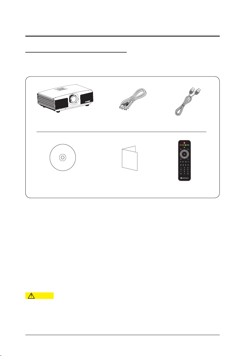
This product is delivered with all the items shown below. Check the packaging to ensure that the items are
complete. If any items are missing, please contact the dealer immediately.
Projector Power cable
Quick start guideUser Manual CD-ROM
HDMI cable
电动聚焦
菜单
退出 信号源
安装方式 空白屏
梯形校正+ 画面比例图像模式 梯形校正-
音量+ 音量- 静音 麦克风
节能
语言
Remote control
Caution
- Because of the differences in the application in each country (region), the products delivered to some
regions may come with different accessories.
11
Page 12
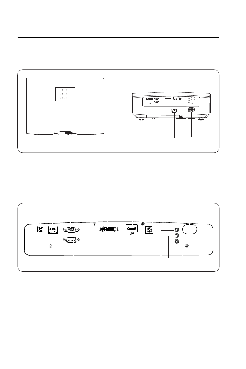
Overview
Projector Appearance
Main unit
④
①
Control panel
①
Projection lens
②
Power interface
③
I/O panel
① ② ③ ④ ⑤ ⑥
⑧ ⑨
USB port (Only used for debugging)
①
RJ45 port
②
③ VGA IN
④
⑤
⑥
port
DVI port
HDMI port
3D OUT port
② ③
⑤ ⑥
Input and output panel
④
Adjustment feet
⑤
Horn hole
⑥
⑩ ⑪
IR port
⑦
RS232 port
⑧
AUDIO IN port
⑨
AUDIO OUT port
⑩
IR WIRED port
⑪
⑦
12
Page 13
Overview
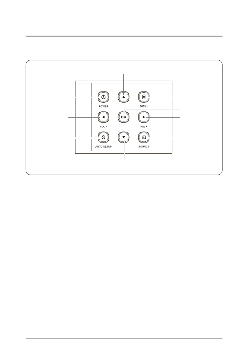
Control panel
②
①
③
⑤
④
⑥
④
⑦
②
POWER button (power-on/off)
①
Press the button to power on the device. In the power-on state, press the button twice to power off the
device.
Arrow keys (Up, Down)
②
When the user menu is displayed, you can press or to select the desired menu item.
When no menu is displayed, you can use the key as a keystone correction shortcut.
MEMU button
③
Access the screen display menu, exit the menu, and save the settings.
VOL +/-/arrow keys ( left, right)
④
- Select items using "" or ".
- Set the volume using "" or "".
OK button
⑤
Press to select or confirm the current value or item.
AUTO SETUP button
⑥
Press to automatically set the parameters.
SOURCE button
⑦
Select different signal sources.
13
Page 14
Overview
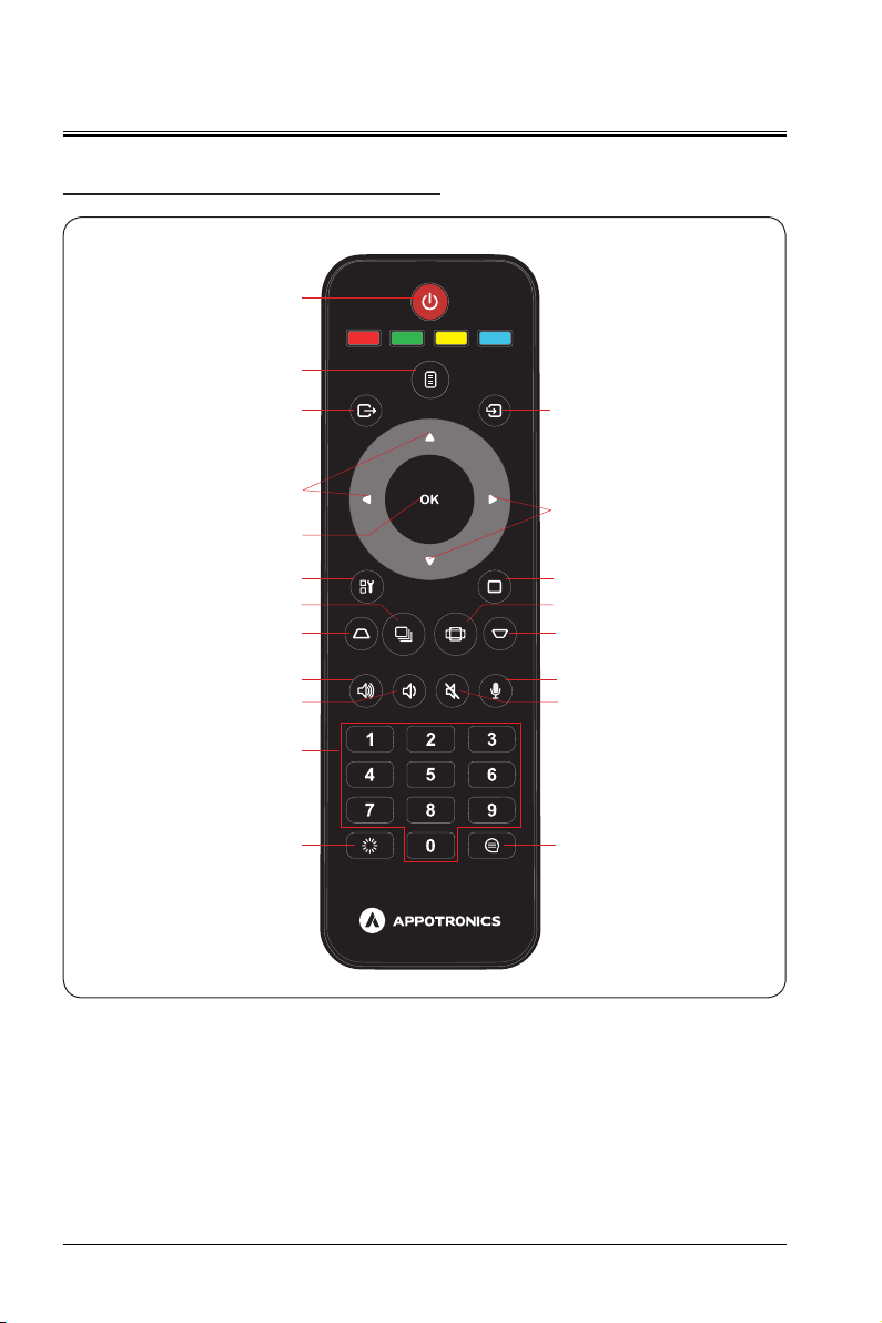
Remote Control
①
②
③
MENU
⑫
SOURCEEXIT
④
④
⑤
⑥
⑦
INSTALLATION
BLANK SCREEN
⑬
⑭
⑧ ⑧
⑨
⑨
KEYSTONE+ KEYSTONE-PICTURE MODE ASPECT RATIO
VOLUME+ VOLUME- MUTE MIC
⑮
⑯
⑩
⑪
SMART ECO LANGUAGE
1 POWER button
In standby mode, if you press this key, the device is powered on; in power-on mode, if you press this key,
the screen prompts for the power-off operation. Press the power button to shut down the device.
2 MENU button
Press to display the main menu. If you press the key again, the main menu disappears or the system
returns to the previous-layer menu.
3 EXIT button
Press to exit the settings.
⑰
14
Page 15

Overview
4
← ↑ ↓ →
You can use ↑ and ↓ to scroll up and down, ← to select from the left or decrease the value, and
select from the right or increase the value.
5 OK button
Press to select or confirm the current value or item.
6 INSTALLATION button
Press to select the projector installation mode. The project supports four projection modes: ceiling rear,
ceiling front, table rear and table front.
7 PICTURE MODE button
Press to switch picture modes among standard, cinema, DICOM SIM, ECO and REC709.
8 KEYSTONE +/- button
Press "+" or "-" to carry out keystone correction.
9 VOLUME +/- button
Press "+" or "-" to adjust the volume.
10 Number keys
Press to enter the corresponding number.
11 SMART ECO button
Press to set the display mode to smart ECO mode.
12 SOURCE button
Press to set the input signal source to HDMI1, HDMI, DVI or VGA.
13 BLANK SCREEN button
Press to switch the picture to the blank screen.
14 ASPECT RATIO button
Set the aspect ratio to 4:3, 16:9, fill or native switching.
15 MIC button
It’s disable for this model.
16 MUTE button
If you press the key, the mute symbol is displayed on the screen, and the device has no audio output; if
you press the key again, the mute symbol disappears, and the audio output resumes.
17 LANGUAGE button
Press to select the desired language.
(arrow keys)
→
to
15
Page 16
Overview
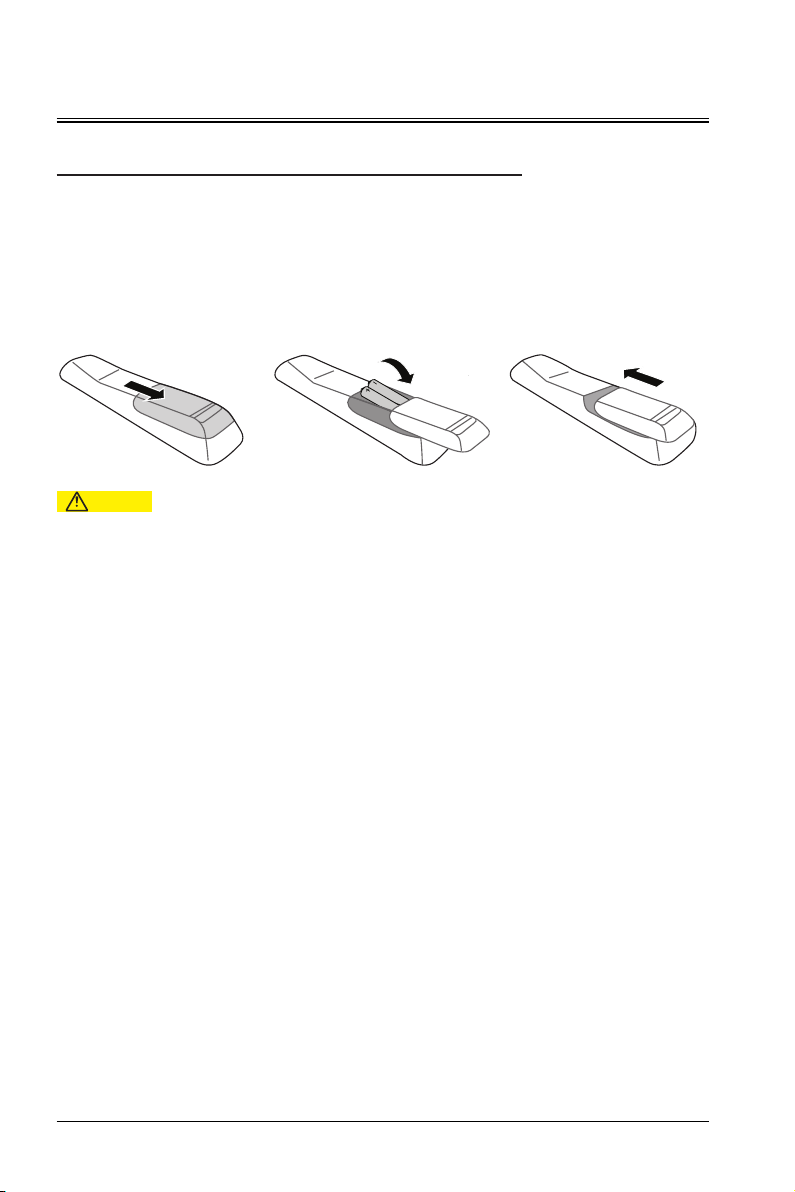
Replacing the Battery of the Remote Control
To open the battery cover, turn the remote control with the back facing up, and pull the battery cover as
indicated by the arrowhead in the figure to remove the battery cover.
Remove the old battery (if necessary) and install the two AAA batteries at the bottom of the battery
compartment. The anode of the battery is towards the (+) direction, and the cathode is towards the (-)
direction.
Reattach the battery cover as indicated by the arrowhead in the figure.
Warning
- Do not place the remote control and battery in high-temperature and high-humidity environments such as
kitchens, bathrooms, saunas, solariums or closed cars.
- Use only the same or similar battery recommended by the battery manufacturer for the remote control.
- Deal with old and waste batteries according to the manufacturer's instructions and local environmental
regulations.
- Do not throw the battery into the fire, since there may be a risk of explosion.
- If the battery is exhausted or the remote control is not used for a long period of time, remove the battery
to avoid damage of liquid leakage to the remote control.
16
Page 17
Overview
Lens shift
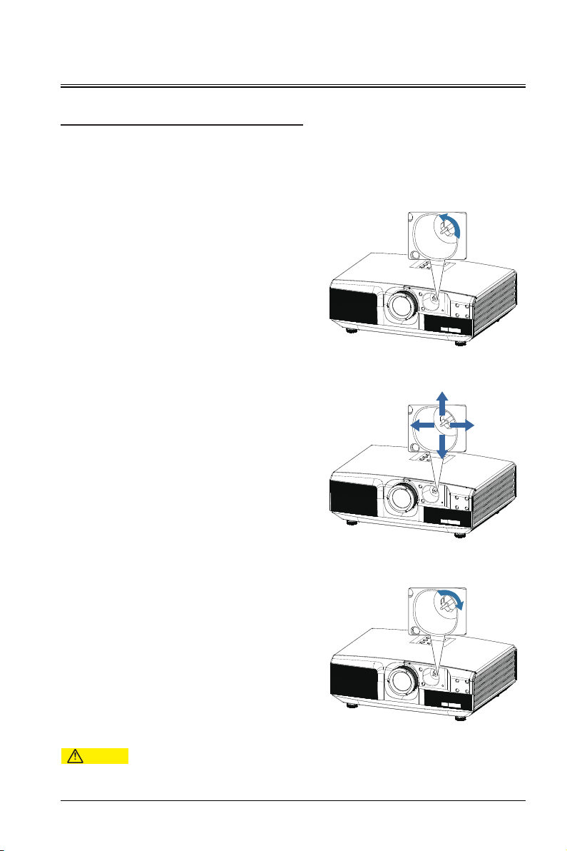
If the projector is not in the center of the screen, you can adjust the projected picture position by moving the
lens shift lever within the lens shift range.
1. Rotate the lens shift lever (counterclockwise) in
the direction indicated in the figure to release the
lock.
2. Adjust the projection position using the lens shift
lever.
Horizontal shift
Adjust the projection by horizontally moving the
lens shift lever according to the placement of the
screen and the projector.
Vertical shift
Adjust the projection by vertically moving the
lens shift lever according to the placement of the
screen and the projector.
3. Rotate the lens shift lever clockwise to secure it.
Caution
-
Do not forcibly shift the lens shift lever. Excessive force may cause the damages to the lever.
17
Page 18

Installation
Projection mode
The projector supports four projection modes. You can install the projector according to the installation
position. Before changing the projection mode, shut down the projector, change the projection mode, and
then start up the projector. The preset projection mode is set to table front. You can change the projection
mode in
Menu > SETUP>INSTALLATION(TABLE FRONT/TABLE REAR/CEILING FRONT/CEILING REAR).
CEILING FRONT
Hang the projector on the wall or ceiling and project the picture from the front of the projection screen.
CEILING REAR
Hang the projector on the wall or ceiling and project the picture from the rear of the semi-transparent
projection screen.
TABLE FRONT
The projection is in the front of the projection screen.
TABLE REAR
The projection is on the rear of the semi-transparent projection screen.
Warning
-
Special installation methods are required to suspend the projector on the wall or ceiling. If not properly installed, the
projector may fall and cause accidents and injuries.
-
If the mounting point on the wall or ceiling hanger frame uses adhesive to prevent the screws from loosening, or the
projector is lubricated with lubricating oil or other oil, the projector case may break, causing the projector to fall. This
may cause the person standing under the hanger frame to be seriously injured and the projector may be damaged.
When installing or adjusting the hanger frame, do not use adhesive to prevent the screws from loosening and do not
use lubricating oil or other oil.
-
Do not cover the projector's air inlet or air outlet. If any air outlet is covered, the internal temperature may rise and
result in system shutdown.
- To ensure the performance and safety of the projector, the installation of the lifting bracket must be carried
out by qualified technical personnel.
18
Page 19
Installation
Adjusting the Projected Picture
Adjusting the protector position
To determine the position where the projector is placed, consider the size and shape of the screen, the
location of the power outlet, and the distance between the projector and other devices. The following are
general principles:
Place the projector on a flat surface and keep a correct angle with the screen.
Place the projector at an ideal location from the screen.
The distance from the projector lens to the screen, the zoom settings, and the video format determine the
size of the projected picture.
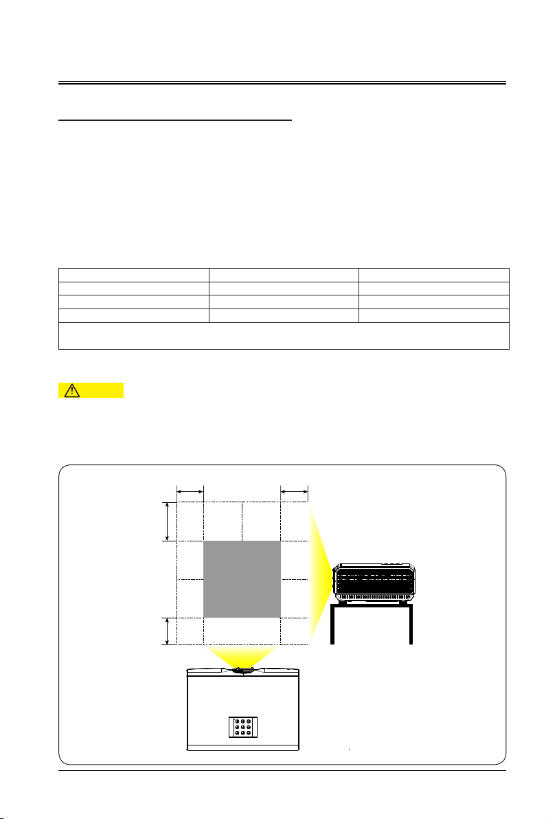
For the picture offset (shift) range of this projector, see the following table:
Resolution H V (V1/V2)
XGA ±35% +50%/-35%
WXGA ±28% +48%/-34%
H: Horizontal offset range of the picture when the lens is centered.
V: Vertical offset range of the picture when the lens is centered.
- The values in the table above are approximate and may differ slightly from the actual values. The actual
values shall apply.
Schematic diagram of horizontal/vertical offset of the picture when the lens is centered (XGA):
1080P ±26% +51%/-36%
Caution
H
V1
V2
H
19
Page 20
Installation
V1
V2
100%
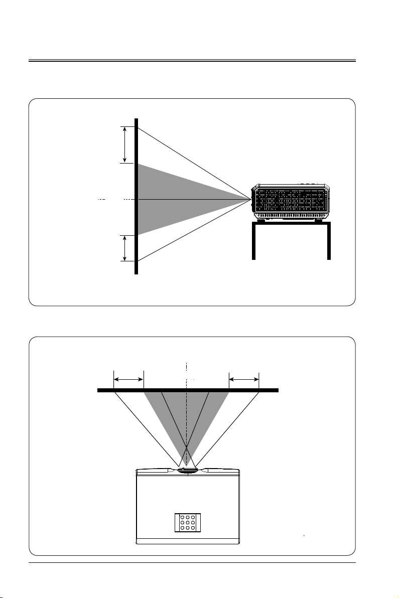
Schematic diagram of vertical offset when the lens is centered
The above table describes the vertical offset ranges (V1/V2) when the lens in different models.
Lens center
Projector screen
Schematic diagram of horizontal offset when the lens is centered
20
Lens center
-35% +35%
100%
100%
Projector screen
Page 21
Device Connection
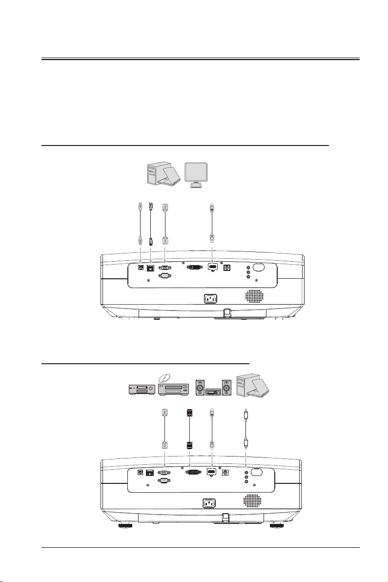
Before connecting the signal source to the projector, confirm the following:
Disable all devices before any connection operation.
Select the appropriate signal cable for each signal source.
Ensure that the power cable is securely inserted.
Connecting the Projector to the PC or Laptop Computer
Connecting to the Audio or Video Device
21
Page 22

Device Connection
Connecting the Projector to the Computer or Display
Connecting the project to the computer
The projector can be connected to a laptop computer or a desktop computer. If the projector needs to be
connected to a computer in an earlier version, configure the corresponding adapter.
Connect the projector to the laptop computer or desktop computer.
Connect one end of the VGA cable to the D-sub output port of the computer.
Connect the other end of the VGA cable to the computer input port of the projector.
Caution
- The external video ports of many laptop computers connected to the projector are not enabled. Generally,
you can enable or disable the external display by pressing Fn+F3 or CRT/LCD.
- On the laptop computer, find the CRT/LCD functional key or the functional key with the display symbol.
Then, press Fn and the marked functional key simultaneously. For details, see the laptop computer
instruction or the composite key description.
Connecting the projector to the display
To enable the display and screen to play the demo simultaneously, connect the computer output port of the
projector to the external display using the VGA cable.
To connect the projector to the display, perform the following steps:
Connect the projector to the computer.
Connect one end of an appropriate VGA cable to the D-sub input port of the video display. If the display
has the DVI input port, connect the DVI end of the VGA-DVI-A cable to the DVI input port of the video
display.
Connect the other end of the cable to the computer output port of the projector.
22
Page 23

Device Connection
Connecting the Projector to the Video Source Device
You can connect the projector to a variety of video signal source devices with the following ports:
HDMI
Component video
S-video
Video (composite video)
You can connect the projector to the video signal source device using any of the preceding connection
methods. The methods correspond to different video quality. The connection method depends on whether
the projector and video source device have the matched terminals.
Best video quality
The optimal video connection method is using the HDMI port. You can enjoy the uncompressed digital video
quality if the source device provides the HDMI port.
For details about how to connect the projector to the HDMI source device, see the chapter "Connecting the
Projector to the HDMI Device".
Good video quality
The S-video connection method provides better analog video compared with the standard composite video.
If the video source device provides both composite video and S-video output sources, you can select the
S-video option. For details about how to connect the projector to the S-video source device, see the chapter
"Connecting the Projector to the S-video Device".
Normal video quality
The S-video connection method provides better analog video compared with the standard composite video.
If the video source device provides both composite video and S-video output sources, you can select the
S-video option. For details about how to connect the projector to the S-video source device, see the chapter
"Connecting the Projector to the S-video Device".
Worst video quality
The composite video is a type of analog video. Although the quality is not the best, it is acceptable. The
video quality of this connection method is the worst compared with the preceding available connection
methods. For details about how to connect the projector to the composite video source device, see the
chapter "Connecting the Projector to the Composite Video Source Device".
23
Page 24

Device Connection
Connecting the Projector to the Audio Source
The projector has a mono speaker designed to provide basic audio features, with commercial data
demonstrations. They are not dedicated to stereo audio reproduction and are intended for home cinemas.
Any stereo audio input (if provided) is mixed through the projector speaker into a common mono audio
output.
The following table shows the sources of the sound when the projector is connected to different signal sources.
Input Signal Source Computer Input S-video or Video Input
The projector can play
the sound from the
following sources.
Connecting the HDMI Device
Check the video source device to determine whether it has an unused HDMI output port.
If available, you can continue to use the program.
If not, you need to reevaluate the methods that can be used to connect to the projector.
Connecting the projector to the device with the HDMI signal source
Connect one end of the HDMI cable (not provided with the projector) to the HDMI output port of the HDMI
signal source.
Connect the other end of the HDMI cable to the HDMI1 or HDMI2 port of the projector. You can select the
display channel using the remote control or the corresponding keys.
Computer audio input AV audio input
24
Page 25

Device Connection
Connecting to the Component Video Device
Check the video source device to determine whether it has an unused component video output port.
If available, you can continue to use the program. If not, you need to reevaluate the methods that can be
used to connect to the projector.
Connecting the projector to the component video source
Connect the end of the component video cable (not delivered with the projector) with three RCA
connectors to the component video output port of the video source device, and ensure that the color of
the connectors maps the color of the ports (green corresponding to green, blue corresponding to blue,
and red corresponding to red).
Connect the other end of the component video cable to the color difference component port. Ensure
that the color of the connectors maps the color of the ports (green corresponding to green, blue
corresponding to blue, and red corresponding to red).
Connecting to the S-video Device
Check the video source device to determine whether it has an unused S-video output port.
If available, you can continue to use the program. If not, you need to reevaluate the methods that can be
used to connect to the projector.
Connecting the projector to the S-video source device
Connect one end of the S-video cable (not provided with the projector) to the HDMI output port of the
S-video signal source.
Connect the other end of the S-video cable to the S-video input port of the projector.
Connecting to the Composite Video Device
Check the video source device to determine whether it has an unused composite output port.
If available, you can continue to use the program. If not, you need to reevaluate the methods that can be
used to connect to the projector.
Connecting the projector to the composite video source
Connect one end of the composite cable (not provided with the projector) to the HDMI output port of the
composite signal source.
Connect the other end of the composite cable to the composite input port of the projector.
25
Page 26

Operation
Powering On the Projector
Insert the power cable to the projector and the wall socket. Switch on the wall socket (if available). Check
whether the power indicator on the projector is on red.
Press the power button on the projector or remote control to power on the projector. After the projector is
on, the indicator is steady on green. If necessary, rotate the focusing ring to adjust the picture definition.
If the projector is initially started up, select the language from the menu as prompted on the screen.
The projector starts to search for input signals. You can also select desired input signals by pressing the
signal source button on the projector or remote control.
Menus
The following figure shows the level-1 menu, including display, picture, source, setup and advance options. You
can move the cursor among these options. The menu supports automatic preview of sub-menus.
DISPLAY PICTURE SOURCE SETUP
ADVANCE
ABOUT
26
Page 27
Operation
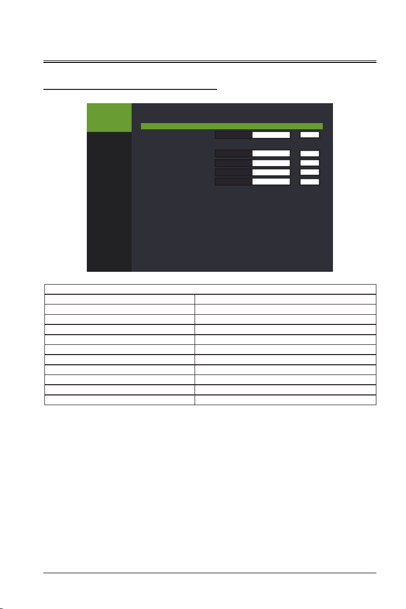
DISPLAY
DISPLAY
PICTURE
SOURCE
SETUP
ADVANCE
ABOUT
ASPECT RATIO FILL
KEYSTONE ADJUST
DIGITAL ZOOM
H-POSITION
V-POSITION
PHASE ADJUST
CLOCK
ASPECT CROP
AUTO KEYSTONE
AUTO REVERSE
DISPLAY
0
>>
0
0
16
0
OFF
OFF
OFF
DISPLAY
Function Attribute Value
ASPECT RATIO FILL, 4:3, 16:9, NATIVE
KEYSTONE ADJUST -40~40
DIGITAL ZOOM >>
H-POSITION -5~5
V-POSITION -5~5
PHASE ADJUST 0~31
CLOCK -5~5
ASPECT CROP OFF, LEFT-TOP, LEFT-BELOW, RIGHT-BELOW
AUTO KEYSTONE ON/OFF
AUTO REVERSE ON/OFF
ASPECT RATIO indicates that the panel resolution is displayed according to the DMD.
KEYSTONE ADJUST is performed manually instead of automatically.
V-POSITION: Depend on the input signal. Its value is uncertain, but it can fine tune the picture display
position.
PHASE ADJUST: When the input signal jitter on the screen jitter, adjust the value to achieve the
appropriate state.
ASPECT CROP: Select the screen position (OFF, LEFT-TOP, LEFT-BELOW, RIGHT-BELOW) of the current
projector in the cropping module.
AUTO KEYSTONE: Automatically perform keystone correction according to the screen position.
AUTO REVERSE: The projector can automatically flip the screen in the ceiling-mounted state, without
separate boot settings.
27
Page 28
Operation
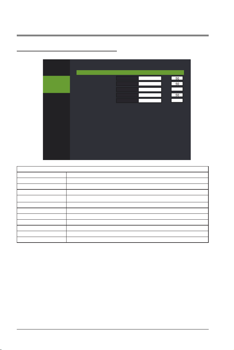
PICTURE
DISPLAY
PICTURE
SOURCE
SETUP
ADVANCE
ABOUT
PICTURE MODE ECO
BRIGHTNESS
CONTRAST
TINT
COLOR
SHARPNESS
COLOR TEMPERATURE
GAMMA
BRILLIANT COLOR
3D COLOR MANAGE
ENHANCE CONTRAST
PICTURE
PICTURE
Function Attribute Value
PICTURE MODE STANDARD, CINEMA, ECO, DICOM SIM, REC709
BRIGHTNESS 0~100
CONTRAST 0~100
TINT -30~30
COLOR 0~100
SHARPNESS 0~31
COLOR TEMPERATURE WARM, COOL, NATIVE
GAMMA CUBIC/Srgb2.2, RGB, FILM, VIDEO, PHOTOGRAPHIC and LINEAR
BRILLIANT COLOR ON/OFF
3D COLOR MANAGE >>
ENHANCE CONTRAST ON/OFF
0
16
NATIVE
RGB
ON
>>
OFF
PICTURE MODE is associated with the brightness, contrast, tint, color, sharpness, color temperature,
gamma, brilliant color, and 3D color management. The tint is adjustable only when the signal source is
video.
>> indicates that you can go to the sub-menu (the same below).
3D COLOR MANAGE: You can adjust the color coordinates and brightness of monochromatic light. This
option is applicable to the advanced user group. Common users are not recommended to change the
setting of this option.
ENHANCE CONTRAST: When this function is enabled, the system improves contrast of the full black and
full white test screens.
28
Page 29
Operation
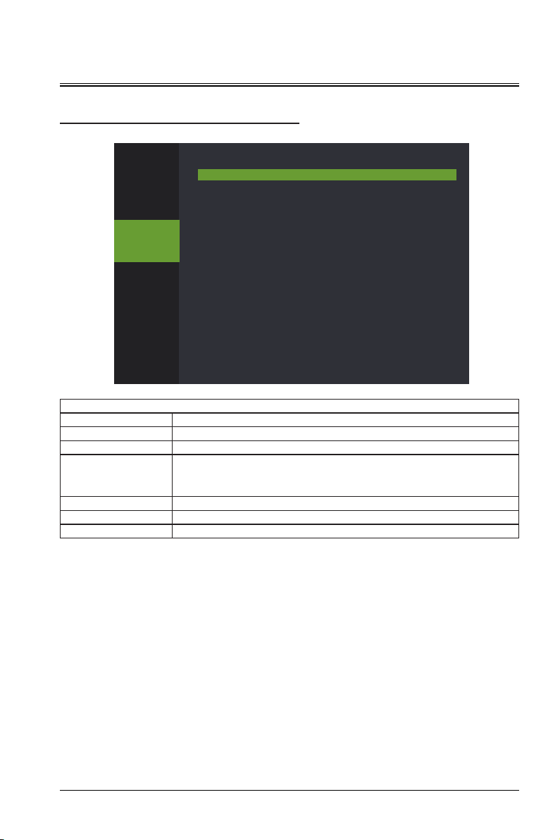
SOURCE
DISPLAY
PICTURE
SOURCE
SETUP
ADVANCE
ABOUT
AUTO DETECT
COLOR SPACE
TEST PATTERNS
BLANK SCREEN
RE-SYNC
RANGE OF RGB
SOURCE
ON
AUTOMATIC
NONE
BLACK
>
AUTOMATIC
SOURCE
Function Attribute Value
AUTO DETECT ON/OFF
COLOR SPACE AUTOMATIC, RGB, YPbPr, and YCbCr
NONE, RGB RAMPS, COLOR BARS, STEP BARS, CHECKERBOARD, GRID,
TEST PATTERNS
HORIZONTAL LINES, VERTICAL LINES, DIAGONAL LINES, HORIZONTAL
RAMP, VERTICAL RAMP
BLANK SCREEN BLACK, BLUE, GRAY, RED, GREEN, YELLOW, GYAN, MAGENTA, WHITE
RE-SYNC >
RANGE OF RGB AUTOMATIC, 0-255, 16-235
Automatic detection indicates that the system automatically detects signal source input within the
supported signal source list in a circular manner until the input is detected.
The test chart and blank screen use the pre-stored pictures and colors to facilitate installation and
commissioning.
Automatic setting indicates that the system re-lock the signal source.
RGB range refers to the range of RGB signal at the time of signal source input.
29
Page 30
Operation
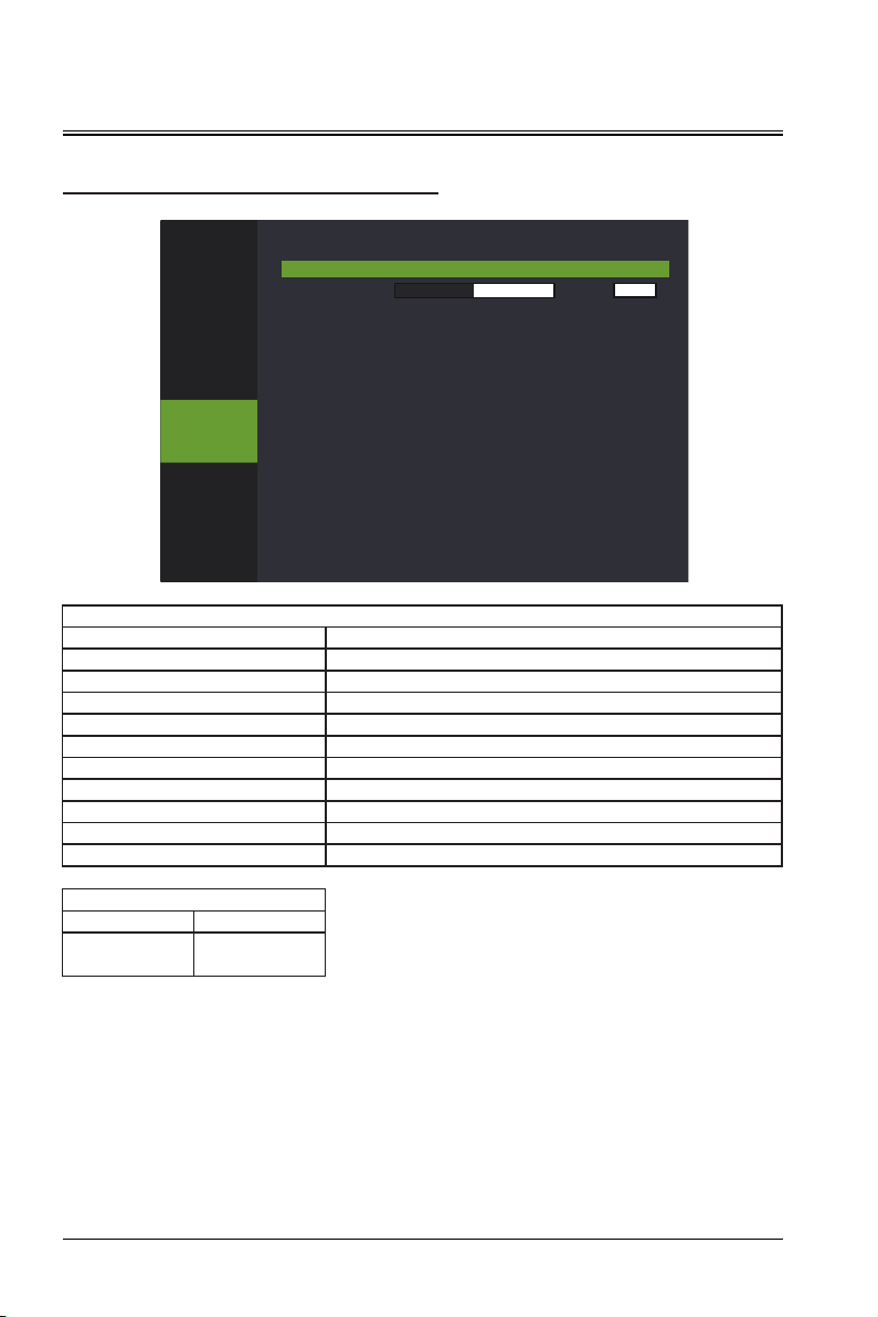
SETUP
DISPLAY
PICTURE
SOURCE
SETUP
ADVANCE
ABOUT
LANGUAGE
VOLUME
SMART ECO
LOGO
SECURITY
KEYPAD LOCK
HIGH LAND
INSTALLATION
STANDBY MODE
SYSTEM RESET
SETUP
5
OFF
OFF
>>
ON
OFF
TABLE REAR
NOMAL
>
SETUP
Function Attribute Value
LANGUAGE >>
VOLUME 0~10
SMART ECO ON/OFF
LOGO ON/OFF
SECURITY >>
KEYPAD LOCK ON/OFF
HIGH LAND ON/OFF
INSTALLATION TABLE FRONT, TABLE REAR, CEILING FRONT, CEILING REAR
STANDBY MODE ULTRALOW, NORMAL, POWER DIRECT
SYSTEM RESET >
AUTHORIZATION MANAGE
AUTHORIZATION ON/OFF
PASSWORD
PRESET
8 digits
30
Page 31

Operation
LANGUAGE refers the language displayed on the menu. The projector supports English, French, German,
Simplified Chinese, Traditional Chinese, Japanese, Korean.
SMART ECO: When this function is enabled, the system automatically enters the power-saving mode if
there is no input and operation in five consecutive minutes. In this mode, the current is about 80% of the
normal mode, in order to achieve power-saving purposes; if there is no input in 10 consecutive minutes,
the system changes to the light source disabled mode; if there is no input in 15 consecutive minutes,
the system changes to the standby mode. When the ambient temperature is higher than 35ºC, the
system automatically enters the power-saving mode to allow the projector to work in even more harsh
environments.
LOGO refers to the logo of the brander displayed in 10s after the projector is powered on.
SECURITY: The system allows you to set the power-on password for the projector to prevent
unauthorized users from using the projector. The password contains 8 Arabic digits and does not support
other characters. If you forget your password, please contact customer service personnel.
KEYPAD LOCK: After the key lock is enabled, the projector's keypad will be invalid, and you can control
the projector only through the remote control or host computer.
HIGH LAND: When using the projector in a high-altitude area, enable the high altitude mode. Otherwise,
the project lifetime may be affected.
STANDBY MODE supports two standby modes, namely, normal standby mode and ultra-low power
standby mode. In normal standby mode, the power consumption is higher than 1 W. The LAN module can
still work, and the network can be waken up. In ultra-low power standby mode, the power consumption
is lower than 0.5 W. The LAN module is powered off, and the network cannot be waken up.
FILTER TIME: When the FILTER TIME function is enabled, the projector records the cumulative time for
using the filter.
FILTER TIME CLEAR: clear the filter used time.
31
Page 32
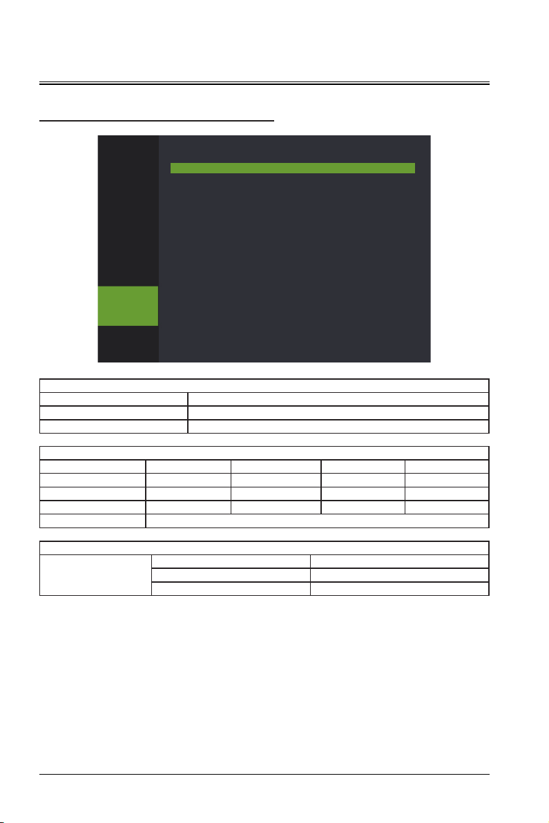
Operation
ADVANCE
DISPLAY
PICTURE
SOURCE
SETUP
ADVANCE
ABOUT
Function Attribute Value
ETHERNET >>
3D >>
IP ADDRESS 0 0 0 0
SUBNET MASK 0 0 0 0
GATEWAY 0 0 0 0
DNS 0 0 0 0
DHCP OFF
FORMAT
ETHERNET
3D
ETHERNET SETTING
VSYNC_SEPARATED_HALF VSYNC_SEPARATED_FULL
VERT_PACKCD_HALF VERT_PACKCD_FULL
HORIZ_PACKED_HALF HORIZ_PACKED_FULL
ADVANCE
>>
>>
ADVANCE
3D SETTING
32
Page 33
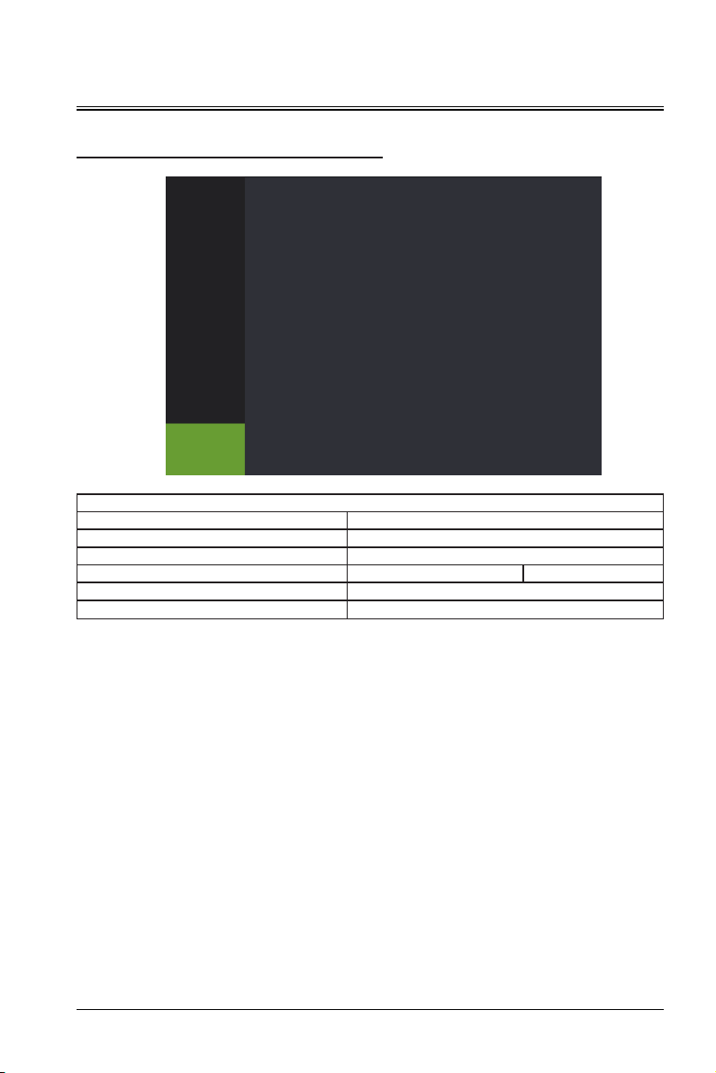
Operation
ABOUT
DISPLAY
PICTURE
SOURCE
SETUP
ADVANCE
ABOUT
ACTIVE SOURCE
INPUT RESOLUTION
ELAPSED TIME
SOFTWARE VERSION
SERIAL NUMBER
ABOUT
HDMI1
0
0 HOURS
0
0
ABOUT
Function Attribute Value
ACTIVE SOURCE >>
INPUT RESOLUTION >
ELAPSED TIME 0 HOURS
SOFTWARE VERSION Vxx
SERIAL NUMBER
ACTIVE SOURCE: When the external signal is input, the current signal channel is displayed; when there is
APPO1234567
no signal input, the screen displays no signal.
INPUT RESOLUTION: Identify the external signal resolution.
ELAPSED TIME: Indicate the accumulative time since the light source is on.
SOFTWARE VERSION: Display the version number of the current software.
SERIAL NUMBER: Indicates the SN used to identify the device.
33
Page 34
Serial Port
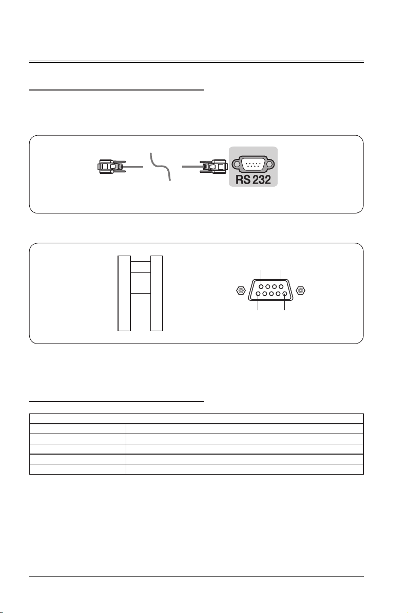
Serial Port
The serial port on the interface board of the projector complies with the RS-232 interface specifications.
Therefore, you can control the projector through the personal computer connected to this port.
(Computer) (Laser projector)
(电脑) (激光投影机)
RS-232 connection diagram
RXD
2
TXD
3
DTR
Computer
*Pin 1 and pin 2 are not connected.
GND
DSR
RTS
CTS
4
5
6
7
8
RXD
2
TXD
3
DTR
4
5
6
7
8
GND
DSR
RTS
CTS
Projector
Communication device
Communication type Serial port RS232
Baud rate 115200
Parity bit NONE
Data bit 8 bit
Stop bit 1 bit
Communication settings
9 6
5 1
34
Page 35
Serial port
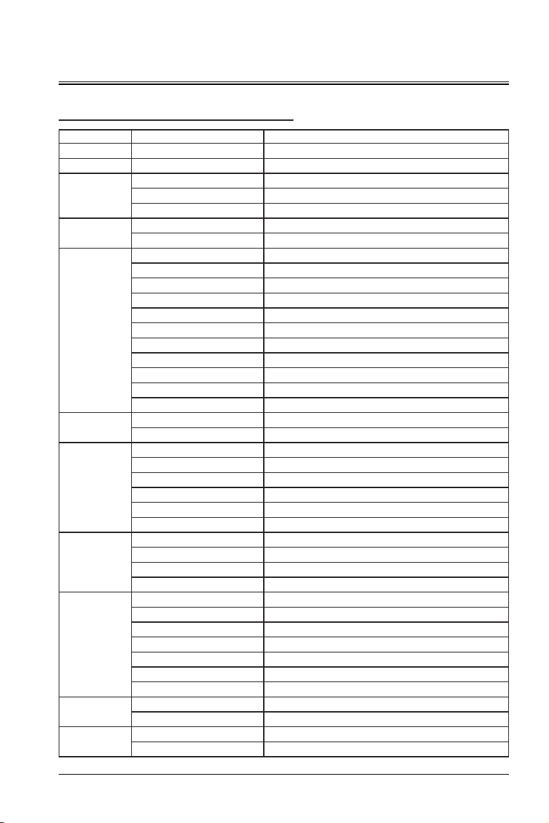
Reference Command List
Control Content Description Hexadecimal Control Code
STARTUP
SHUTDOWN
SOURCE
SOUND
VOLUME
SETTINGS
VOLUME
PICTURE
MODE
ASPECT RATIO
3D SETTING
SMART ECA
KEYPAD LOCK
HDMI EB 90 00 0C 00 00 08 01 00 02 01 93
DVI EB 90 00 0C 00 00 08 01 00 02 02 94
VGA EB 90 00 0C 00 00 08 01 00 02 03 95
ON EB 90 00 0C 00 00 08 01 00 03 00 93
OFF EB 90 00 0C 00 00 08 01 00 03 01 94
0 EB 90 00 0C 00 00 08 01 00 04 00 94
1 EB 90 00 0C 00 00 08 01 00 04 01 95
2 EB 90 00 0C 00 00 08 01 00 04 02 96
3 EB 90 00 0C 00 00 08 01 00 04 03 97
4 EB 90 00 0C 00 00 08 01 00 04 04 98
5 EB 90 00 0C 00 00 08 01 00 04 05 99
6 EB 90 00 0C 00 00 08 01 00 04 06 9A
7 EB 90 00 0C 00 00 08 01 00 04 07 9B
8 EB 90 00 0C 00 00 08 01 00 04 08 9C
9 EB 90 00 0C 00 00 08 01 00 04 09 9D
10 EB 90 00 0C 00 00 08 01 00 04 0A 9E
+ EB 90 00 0C 00 00 08 01 00 05 01 96
- EB 90 00 0C 00 00 08 01 00 05 00 95
STANDARD
CINEMA
DEMO
ECO
DICOM SIM
REC709
FILL
NATIVE
4:3
16:9
OFF
VSYNC_SEPARATED_HALF
VSYNC_SEPARATED_FULL
VERT_PACKED_HALF
VERT_PACKED_FULL
HORIZ_PACKED_HALF
HORIZ_PACKED_FULL
ON
OFF
ON
OFF
EB 90 00 0C 00 00 08 02 00 01 01 93
EB 90 00 0C 00 00 08 01 00 01 00 91
EB 90 00 0C 00 00 08 01 00 07 01 98
EB 90 00 0C 00 00 08 01 00 07 02 99
EB 90 00 0C 00 00 08 01 00 07 03 9A
EB 90 00 0C 00 00 08 01 00 07 04 9B
EB 90 00 0C 00 00 08 01 00 07 05 9C
EB 90 00 0C 00 00 08 01 00 07 06 9D
EB 90 00 0C 00 00 08 01 00 08 01 99
EB 90 00 0C 00 00 08 01 00 08 02 9A
EB 90 00 0C 00 00 08 01 00 08 03 9B
EB 90 00 0C 00 00 08 01 00 08 04 9C
EB 90 00 0C 00 00 08 01 00 09 00 99
EB 90 00 0C 00 00 08 01 00 09 01 9A
EB 90 00 0C 00 00 08 01 00 09 02 9B
EB 90 00 0C 00 00 08 01 00 09 03 9C
EB 90 00 0C 00 00 08 01 00 09 04 9D
EB 90 00 0C 00 00 08 01 00 09 05 9E
EB 90 00 0C 00 00 08 01 00 09 06 9F
EB 90 00 0C 00 00 08 01 00 0A 01 9B
EB 90 00 0C 00 00 08 01 00 0A 00 9A
EB 90 00 0C 00 00 08 01 00 0E 01 9F
EB 90 00 0C 00 00 08 01 00 0E 00 9E
35
Page 36
Maintenance
Projector Maintenance
The projector needs to be maintained. You need to regularly clean the lens.
You can power on the projector only after the surface water is dried if you clean the lens or enclosure.
Do not disassemble any parts of the projector. To replace the parts, please contact the dealer.
Cleaning the lens
You can clean the lens when you find that the lens surface is stained or dusty.
Use a compressed air tank to remove dust.
If there is dust or stain, gently wipe the lens surface using the lens paper or damp cloth with some
cleaning agent.
Caution
- Do not rub the lens with abrasive materials.
Cleaning the projector enclosure
To remove dirt or dust, wipe the enclosure with a soft, lint-free cloth.
To remove strong dirt or spots, wet the soft cloth using water and neutral pH detergent, and then wipe the
enclosure.
Caution
- Do not use wax, alcohol, benzene, thinner, or other chemical cleaners because these substances can
damage the enclosure.
Storing the projector
If you need to store the projector for a long period of time, follow the instructions below:
Ensure that the temperature and humidity of the storage area are within the recommended range for the
projector.
Retract the adjustment feet.
Remove the battery from the remote control.
Use the projector's original packaging or equivalent material to package the projector.
Transporting the projector
It is recommended to use the original packaging or equivalent material when transporting the projector.
36
Page 37
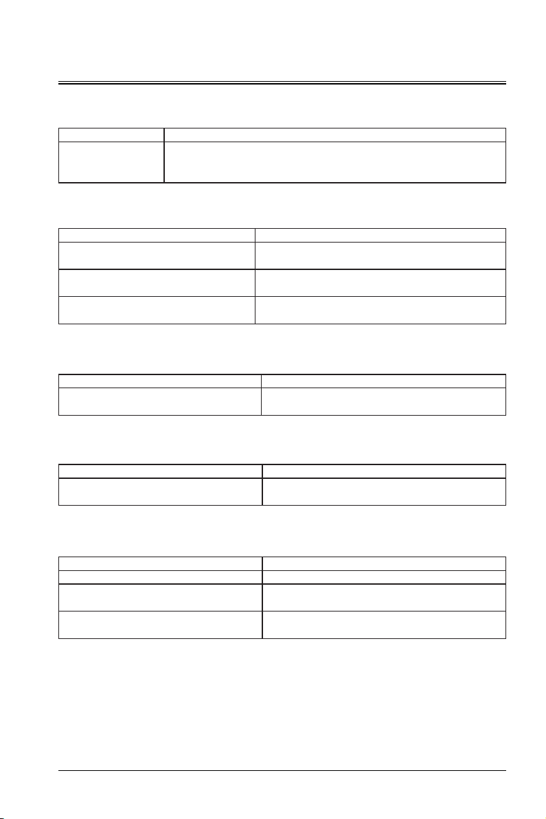
Troubleshooting
The projector fails to power on.
Cause Solution
The power cable
supplies no power.
No picture
The video signal source is not enabled or is
incorrectly connected.
The projector and the input signal device are
not properly connected.
The input signal is not correctly selected.
The picture is fuzzy.
The projector does not accurately align with the
screen.
The picture is deformed.
The screen is not smooth.
Insert one end of the power cable to the AC port on the projector, and insert the
other end to the electrical outlet. If the electrical outlet has a switch, ensure that
the switch is turned on.
Cause Solution
Enable the video signal source and check whether the
signal cable is properly connected.
Check the connection.
Select the correct input signal source using the signal
source key on the projector or remote control.
Cause Solution
Cause Solution
Adjust the projection angle and direction. If necessary,
adjust the projector's height or distance.
Professional screens such as digital board are
recommended.
The remote control fails.
The battery level is low. Replace the battery.
There are obstacles between the remote control
and the projector.
The distance to the projector is too far.
Cause Solution
Move the obstacles.
The distance to the projector should be no longer than
5 m (16 inches).
37
Page 38
Troubleshooting
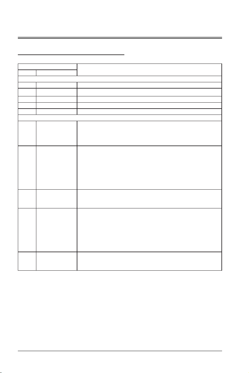
Indicator
Red Green
Blinking Off Protection state upon safety switch anomalies
Light
Off Off Power-off
On Off Standby mode
Off On Power-on state
Off Blinking Protection state upon running anomalies
[Safety protection]: When the projector is powered on, safety protection is
Off Blinking
Blinking twice -
Off
pause - blinking for
five times
Blinking twice -
Off
pause - blinking for
six times
Blinking twice -
Off
pause - blinking for
three times
Blinking twice -
Off
pause - blinking for
four times
triggered when the top cover is opened, regardless of whether the projector
is in the standby state or the power-on state. After safety protection is
triggered, the red LED indicator on the rear panel blinks.
[Light source protection]: Light source protection is triggered when the light
source temperature NTC is no lower than 79ºC or is higher than 0ºC for
120s. If the temperature after the startup is 0ºC and the following software
considers that the NTC data collection is abnormal, that is, the light source
temperature NTC is no lower than 79ºC or is higher than 0ºC, the green
LED indicator blinks for 2+5s (the former is over-temperature and the latter
is under-temperature).
[Temperature protection]: Temperature protection is triggered when the
ambient temperature NTC is lower than 0ºC or is higher than 40ºC for 120s.
The green LED indicator blinks for 2+6s.
[Color wheel protection]: During the startup, to enable the laser, the color
wheel speed must reach 90-150 Hz. During normal operation, the color
wheel speed is considered abnormal if it is lower than 90 Hz or higher
than 150 Hz. The protection reaction interval triggered by the color wheel
anomaly is shorter than 1s. That is, shutdown protection is enabled when
the color wheel speed deviates from 90-150 Hz for 1s. The green LED
indicator blinks for 2+3s.
[Fan protection]: After the startup, if any fan stops working for 60s, fan
protection is triggered. The green LED indicator blinks for 2+4s.
Course light
System protection
State and Indication
38
Page 39
APPOTRONICS Co., Ltd
Address: 20F to 22F, High-Tech Zone Union Tower, No.63 Xuefu Road, Nanshan District,
Shenzhen, Guangdong, P. R. China
Website: www.appotronics.com
P/N: D66050000050
Version: A
.
 Loading...