

Applied Research and Technology (ART) DMV-Pro Owner's Manual
7KH$57
3URJUDPPDEOH 'LJLWDO (IIHFWV 3URFHVVRU
TABLE OF CONTENTS
Introduction .................................................................................................................................................................... 1
Installation ...................................................................................................................................................................... 2
AC Power Hookup .................................................................................................................................................... 2
Audio Connections .................................................................................................................................................... 2
Safety Precautions .................................................................................................................................................... 2
Quick Start Instructions ................................................................................................................................................ 3
Quick Setup .............................................................................................................................................................. 3
With a Mixer .............................................................................................................................................................. 3
Straight into an Amp ................................................................................................................................................. 4
In an Amp’s Effects Loop .......................................................................................................................................... 4
Try It Out ................................................................................................................................................................... 5
Selecting Presets ...................................................................................................................................................... 5
DMV-PRO Front Panel Controls and Indicators ..........................................................................................................6
Processors (A) & (B) ................................................................................................................................................. 6
Power ........................................................................................................................................................................ 6
LCD ........................................................................................................................................................................... 6
Edit Button ................................................................................................................................................................ 6
Processor (A) & (B) Encoder / Switch ....................................................................................................................... 7
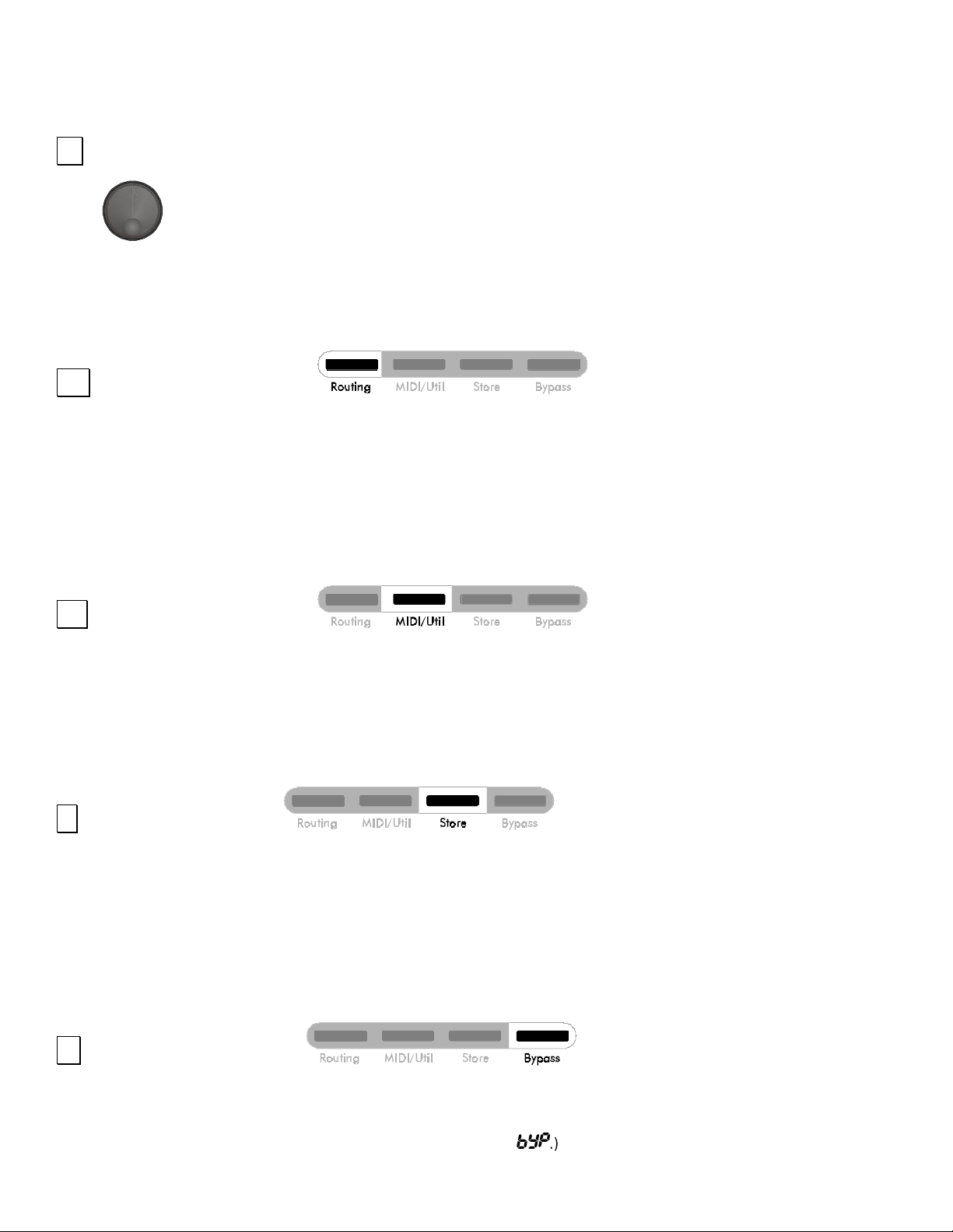
Routing Button .......................................................................................................................................................... 7
MIDI/Util Button ......................................................................................................................................................... 7
Store Button .............................................................................................................................................................. 7
Bypass Button ........................................................................................................................................................... 7
Preset Encoder / Switch ........................................................................................................................................... 8
Selection Arrow ......................................................................................................................................................... 8
Processor (A) & (B) Meters ....................................................................................................................................... 8
- i -

Routing LEDs ........................................................................................................................................................... 8
Unloaded Preset Indicator ........................................................................................................................................ 9
Preset Display ......................................................................................................................................................... 9
Special Functions: .................................................................................................................................................... 9
Restoring Presets to Original Factory Settings .................................................................................................. 9
Dry Kill and Global Mix ..................................................................................................................................... 10
Setting Dry Kill and Global Mix ........................................................................................................................ 11
MIDI Dump ....................................................................................................................................................... 11
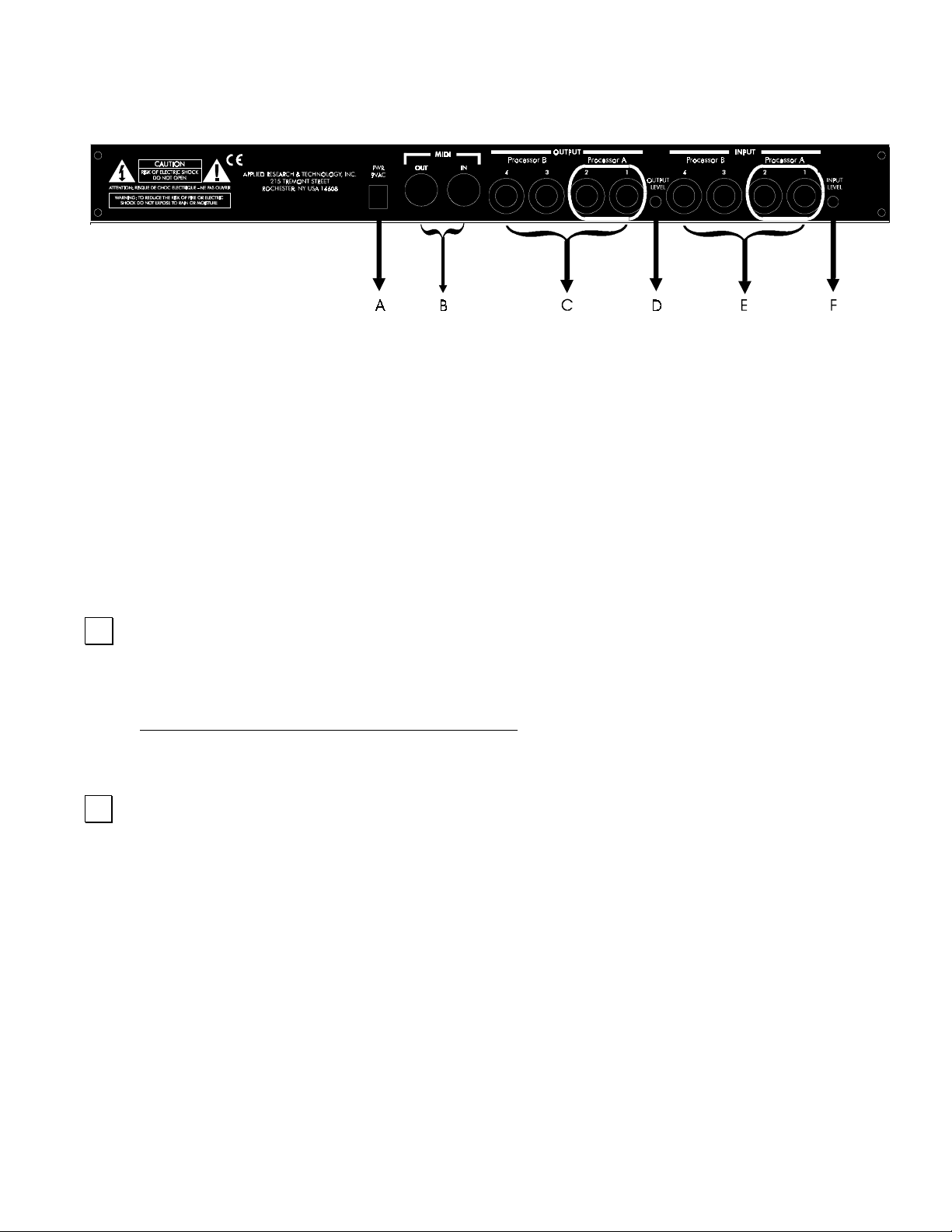
DMV-PRO Rear Panel Controls and Connections ................................................................................................... 12
Power Jack Input .................................................................................................................................................... 12
MIDI In & MIDI Out ................................................................................................................................................. 12
Outputs #1–4 .......................................................................................................................................................... 13
Output Level Switch ............................................................................................................................................... 13
Inputs #1–4 ............................................................................................................................................................. 13
Input Level Switch .................................................................................................................................................. 13
Tutorial ......................................................................................................................................................................... 14
Introduction ............................................................................................................................................................. 14
Tutorial 1: Starting from Scratch and Changing Effects ......................................................................................... 16
Tutorial 2: Editing Effect Parameters ..................................................................................................................... 18
Tutorial 3: MIDI ....................................................................................................................................................... 19
Editing the Global MIDI Parameters ................................................................................................................ 20
An Effect’s MIDI Parameters ............................................................................................................................ 21
Tutorial 4: Advanced Applications .......................................................................................................................... 23
The Smart Encoder .......................................................................................................................................... 23
Smart Encoder Programming .......................................................................................................................... 24
Using a Smart Encoder Function in Preset Mode ........................................................................................... 24
Smart Encoder Functions while Editing Reverb, Delay, and Rotary Effects ................................................... 25
The DMV-PRO’s Adjustable Parameters .................................................................................................................. 26
Description of Routings and Engines ..................................................................................................................... 26
Description of Classes ............................................................................................................................................ 28
Description of Effects and Their Parameters ......................................................................................................... 28
Common Parameters ....................................................................................................................................... 28
Chamber Reverb .............................................................................................................................................. 31
Room Reverb ................................................................................................................................................... 31
Hall Reverb ...................................................................................................................................................... 31
Plate Reverb .................................................................................................................................................... 31
Digital Delay ..................................................................................................................................................... 35
Pitch Transposer .............................................................................................................................................. 38
- ii -

Modulated Effects ............................................................................................................................................. 40
Chorus ....................................................................................................................................................... 40
Flanger ....................................................................................................................................................... 40
Phaser ....................................................................................................................................................... 40
Tremolo ..................................................................................................................................................... 40
Panner ....................................................................................................................................................... 40
Rotary ............................................................................................................................................................... 44
MIDI/Util Parameters .............................................................................................................................................. 46
Channel Number / MIDI Dump ......................................................................................................................... 46
MIDI Map .......................................................................................................................................................... 46
Dry Kill / Global Mix .......................................................................................................................................... 47
LCD View Angles / Factory Reset .....................................................................................................................47
Reference ..................................................................................................................................................................... 48
DMV-PRO Factory Preset List ................................................................................................................................ 48
LFO Shapes ............................................................................................................................................................ 50
MIDI Implementation in the DMV-PRO ................................................................................................................... 51
MIDI Controllers and Numbers ................................................................................................................................53
Warranty Information .............................................................................................................................................. 54
Service .................................................................................................................................................................... 54
DMV-PRO Specifications ........................................................................................................................................ 56
- iii -


INTRODUCTION
Thank you for purchas ing a DMV-PRO and congratu lations! You now own one of the mos t sophisticated pieces of
audio signal-processing technology available. The DMV-PRO uses state-of-the-art DSP techniques combined with
A R T’s proprietary Dynamic Engine A llocation (DEA™) soft ware to give you control over a multitude of brand new,
stunning effects algorithms—many of which have never been heard before. The DMV-PRO is the world’s first
affordable
access to all of its features.
dual true-stereo, multi-ef fects processor and its straightforward user interfac e quickly and easi ly gives you
FEATURES:
• Four discrete inputs, outputs, and audio processing channels
• 20 bit A/D – D/A converters on all four inputs and outputs
• 46.875 kHz sample rate
• Radically new effect algorithms: reverb, rotary, phaser, flanger, chorus, panner, pitch shift, tremolo, and delay
• Six algorithmic variations of each effect
• Dynamic effects with parameters that change in response to the input signal level
• A R T’s proprietary Dynamic Engine Allocation (DEA™)
• Performance MIDI™ real-time control
• Fully programmable
• Designed and manufactured in the USA
Fill in the following information for your reference:
Date of purchase ___________________
Purchased from ___________________
Serial number ___________________
416–5004–101
- 1 -

INSTALLATION
The DMV-PRO may be us ed in a var iety of setups including with mixer channel inserts , mixers with rever b send an d
return facilities, an d in the effec ts loop of an instrum ent or P.A. amplif ier. Self-c ontained in an all-ste el, single-heig ht
19” rack-mount enclosure, the DMV-P RO is designed for c ontinuous professional use. B ecause the unit is com pact
and lightweight, mounting locat ion is not cr itical. However, for greater r eliab ility we recom mend tha t you not place the
DMV-PRO on top of power amps, tube equipment, or other sources of heat.
AC POWER HOOKUP
The DMV-PRO has an external power supply designed to operate at 110 VAC @ 50 to 60 Hz. Units
manufactured for use outside the United States of America have bee n modified to comply with the required
electrical specifications.
damaged, contact A R T Customer Service for replacement.
Only use the adapter that came w ith t he DMV-PRO.
AUDIO CONNECTIONS
All audio connecti ons to and from the DMV-PRO are ¼” unbalanced TS (T ip = Hot, Sleeve = Ground). W e
recommend using only high-quality shielded cables equipped with high-quality connectors.
SAFETY PRECAUTIONS
Warning:
personnel. Do not rem ove the metal covers ; there are no user-servic eable parts inside. O nly use the power
adapter that came with this unit or one obtained from A R T’s Customer Service Department.
To avoid the risk of shock or f ire, do not ex pose this uni t to m oisture. R ef er all s ervic ing to qual ified
If the adapter becom es los t or
- 2 -
QUICK START INSTRUCTIONS
You’ve unpacked your DMV-PRO and you’re in a hurry to get it u p an d running. You probably would rather pl a y wit h it
than read the manua l. Fair enough. First, check out the basics, outlined her e, just to get your DMV-PRO on-line . It
should take only a cou ple of m inutes f or you to read thr ough th is sectio n and then you’ll be re ad y to fir e up your ne w
unit. Later, when you want to get into more of the details, check out the rest of the manual.
QUICK SETUP:
Plug the AC adapter into t he back of the DMV-PRO and then int o a wal l soc ket. Make sure that both the Input
Level and Output Level switches (on the back of the unit) are fully out. You may need to depress these
switches later, after the other setup steps are done.
NOTE: For all input and output connections, always use high quality, shielded cables.
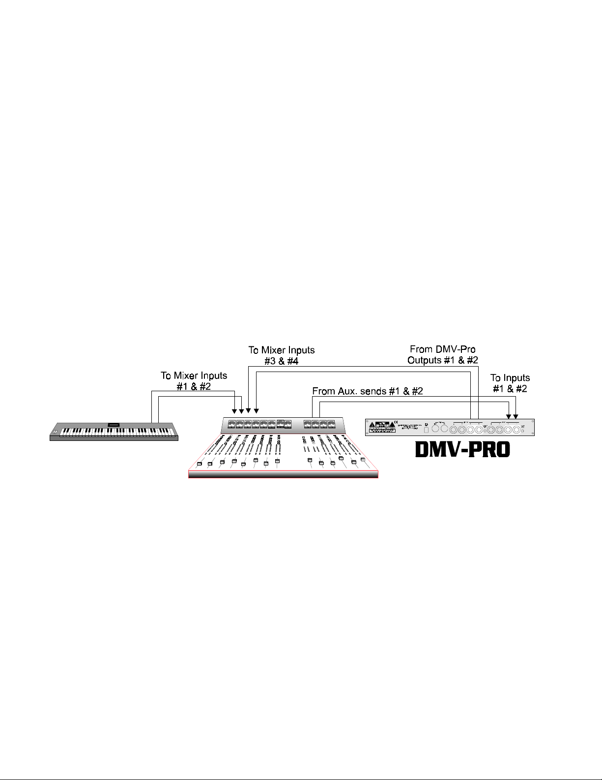
WITH A MIXER:
Connect two cords with ¼” p lu gs bet wee n your mixer’s auxiliary sends and the DMV - PRO’s Inputs #1 and #2.
For a mixer with a mono send, use on ly Input #1. Connect Outputs #1 and #2 to two input cha nnels or the
returns on your mixer.
The DMV-PRO can be used as two separate, stereo effect-processors. Inputs and Outputs #3 and #4
correspond to the DMV-PRO ’s second stereo eng ine. Again, if your m ixer has a mono send, use only Input
#3. The DMV-PRO can e ven b e used as four com pletely ind epende nt, m ono eff ect-pr ocess ors. As you wou ld
expect, Inputs #1–4 correspond with Outputs #1–4.
IMPORTANT: If you are patched in a send/return fashion and mixing an instrument’s dry (unprocessed) signal
with processed sound fr om the DMV-PRO (on separat e faders), you will want to r emove all dry signal fr om
the DMV-PRO’s internal mix buss (signal path). This allows the dry signal to appear only once at the m ixing
board and not additionally at the DMV-PRO’s faders. One way to do this is to set EACH preset’s Mix
parameter to 100%. That would be a tedious process! Fortunately, there is a special DMV-PRO function
- 3 -
called Dry Kill that will conveni ently turn of f the dry signal p ath inside t he unit. Each pr eset’s Mix value is st ill
retained, even though all dry sound is eliminated. To enable Dry Kill, turn on the DMV-PRO and press the
MIDI/Util button. Tur n the Preset Encoder (the k nob on the far right of the unit) until the top lin e of LCD (A)
reads: “Dry Kill:” then turn Processor (A)’s encoder until “ON” appears on the bottom line. By enabling Dry Kill,
you have turned off or “k illed“ the path for dry sound. Press the MIDI/Util button again to exit th e MIDI/Util
Mode. For more information on Dry Kill, see page 10.
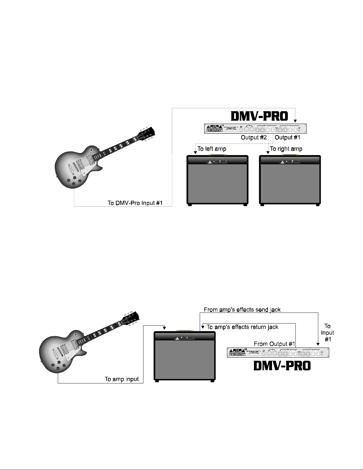
STRAIGHT INTO AN AMP:
If you’re patching the DMV-PRO into an instrument amplifier or stereo monitor amplifier, use one cord
between the instrum ent and the DM V-PRO’s Inp ut #1. R un a second cord fr om Output # 1 to the am p’s input.
If the amp has stereo input capabilities, or if you ’re using tw o amps, c onnect anot her cord between the DMVPRO’s Output #2 and the amplifier’s other input. You c an also p lug a second o utput from your instrum ent (or
the output from another instrument) into the DMV-PRO’s Input #2. Don’t forget that the DMV-PRO can also be
used as two separate, stereo processors, or even as four separate, mono processors. Imagine the Power!
IN AN AMP’S EFFECTS LOOP:
If you’re patching the DM V-P R O in to a guitar (or other instrument) amplifier’s mono effects loop, use one cord
between the amp’s Effec ts Send jack and the DMV-PR O’s Input #1. Run a secon d cord f rom O utput #1 to th e
amp’s Effects Return jack. (If the amp has stereo returns, use another cord to connect the DMV-PRO’s
Output #2 to the amp’s other Effects Return jack .) Again, don ’t forget that th e DM V-PRO has the p o wer to act
as two separate, stereo processors or four separate, mono processors.
- 4 -

TRY IT OUT:
Turn on your amp or mixer and monitor amplifier.
Make sure that your mixer’s or amp’s send le vel control is turned up a nd that a signal is being sent to the
DMV-PRO. Watch the Meters on the front of the unit. Most of the l ights (LEDs) should be on, except for the
+6 LED, which should only glow when a really loud, instantaneous signal reaches the unit. If the +6 LED
glows constantly, turn down th e sen d lev el fr om your m ixer or instrum ent. If only a f e w LEDs g low, either t urn
up your mixer’s send level, or depress the Input Level switch on the back of the unit and then adjust the
mixer’s send level accordingly.
Now raise the return leve l on your mixer or am p. You should b e hearing th e DMV-PRO’s ef fect. If not, check
your connections and your m onitor amp. Make s ure that the DMV-PRO ’s Bypass butto n hasn’t been p ushed
accidentally; if it has , the Preset Display will r ead
panel Bypass button. If the DMV-PRO’s level seems too hig h, d epr es s the Output Level switch o n th e b ac k of
the unit.
SELECTING PRESETS:
The DMV-PRO is in
(on the far right) to any preset number that you desire. Notice that the information on the front-panel has
changed to reflect the new pres et’s configur ation. Als o notice that t he Load L ED (above the n umeric dis play)
is lit to indicate th at you are looking at an unloade d pres e t. You won’t hear an unloaded preset until you press
the Preset Encoder to load i t. For a list of Factor y Pres ets, arr ange d accor ding to num ber an d t ype, see pag e
48. Editing effects will be covered later in this manual.
NOTE: The DMV-PRO can handle up t o two stereo channels and up to four mono channels, depending on
how a preset is internally “routed.” Some of the factory presets may use a routing scheme (Twin Stereo,
Cascade, Discrete 4, or Mult i FX) that is d iff erent f rom how your r ig is cur rentl y co nfigur ed. You m ay no t he ar
what you would expect to he ar. For instanc e, you may be set up to only m onitor stereo outputs ( #1 and #2),
Preset Mode
-,
when it is powere d up. Select a new preset by tur ning the Preset Encoder
To turn Bypass either of f or on, press the front-
and you may be listening to a preset that creates four separate flangers in a Discr ete 4 routing (four effec ts
with separate inputs and outputs). Obvi ously, you wil l not hear all f our flangers because you are not liste ning
to Outputs #3 and #4; you wil l onl y hear t he two f langer s at Ou tputs #1 and #2. Unmatched routing schem es,
however, can still produce creative results. For example, in the previous situation, the Discrete 4 flanger
preset would yield a stereo flanger, but with com pletely independent (unlink ed) left and right channel sweep
widths and rates! When is the last time you easily created THAT effect? The DMV-PRO has many sim ilarly
unique sounds and features, all of which will be covered in the rest of th is manual. For your reference, m ore
information on the concept of routings can be found on page 26 and a list of all factory presets and their
routings begins on page 48.
- 5 -
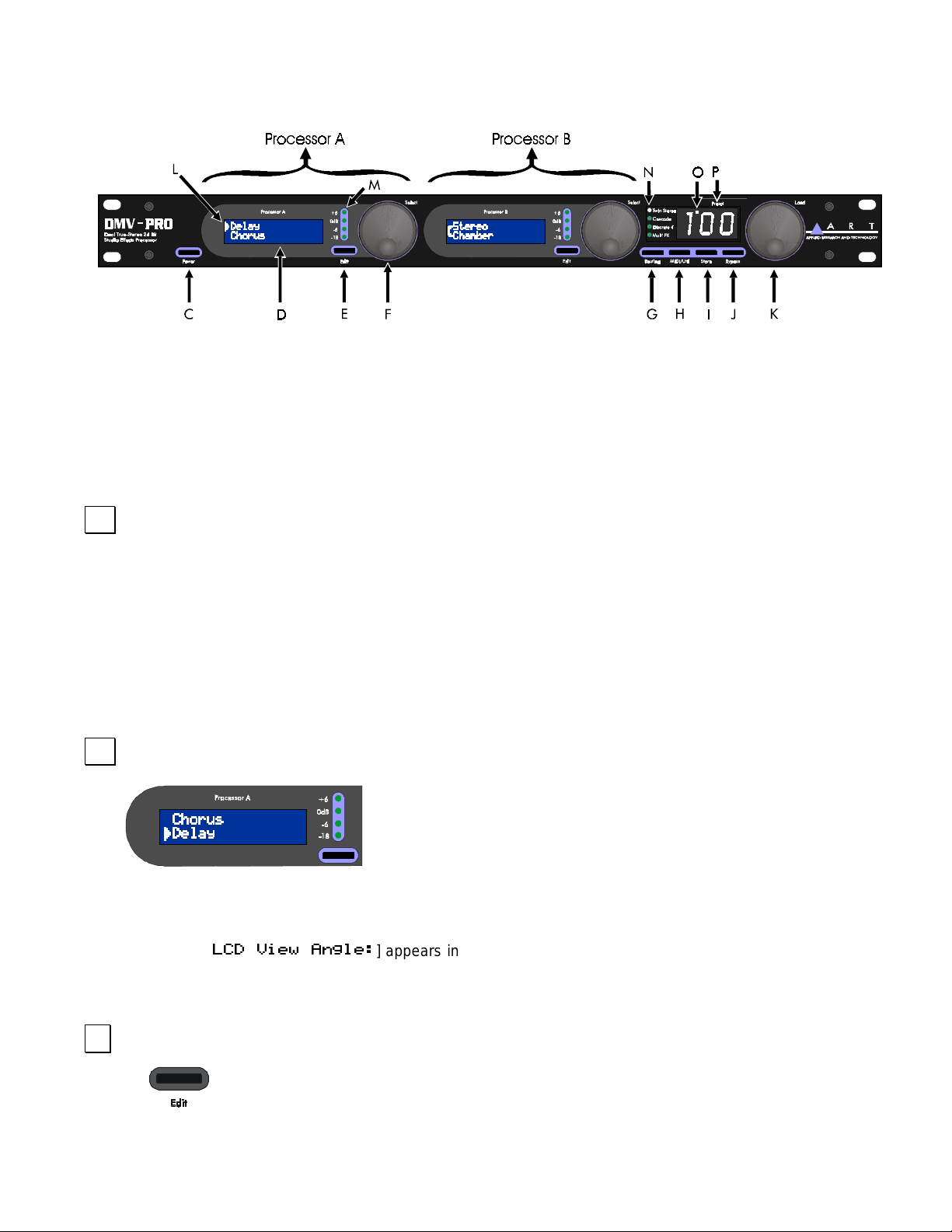
DMV-PRO FRONT PANEL CONTROLS & INDICATORS
PROCESSORS (A) AND (B)
The DMV-PRO contains two audio processors, labeled Processor (A) and Processor (B). Each can be
operated independently from the other. The controls for each processor operate similarly and are outlined
below.
&
POWER
The Power switch turns the DMV- PRO on and of f. The Numer ical Display W indow and both LCDs il luminate
when power is on. If the unit does not turn on when this switch is toggled, check the AC power cord and
adapter. Also, make sure the outlet that it is plugged into is “live,” by p lugging in anot her piece of equi pment
that you know works (try plugging into an other outlet, too). If the outl et is good but the DMV-PRO does not
turn on, consult your dealer or A R T Cus tomer Service. The DMV-PRO is in Pr eset Mode when it is first
turned on.
'
LCD (A) AND (B)
To set the LCD View An gl e of the displays, press the MIDI/Util butt on and then turn the Preset Encoder to the
right until [
LCDs. Press the MIDI/Util button to return to the previous mode.
($5 T&+$A
The DMV-PRO contains two Liquid Crystal Displays—LCD (A) and LCD
(B). Both displays se parately show information about the ir corresponding
processor and when the MIDI/Util button is pressed, they both work
together for viewing global parameters.
] appears in LCD (A). Turn Encoder ( A) until the contras t is better for both
(
EDIT BUTTONS (A) AND (B)
The Edit buttons are used for viewing each processor’s effect parameters. From Preset Mode,
press Edit and turn the same processor’s Encoder to view each effect parameter. To modify a
parameter, press the Encoder and then turn it to change values. Repeatedly pressing the Encoder will toggle
- 6 -
the Encoder’s function between selecting parameters and changing values. For more information on
parameters, see page 28.
)
PROCESSORS (A) & (B) ENCODER / SWITCH
The first two Encoders are used separately to view and modify their corresponding processor’s
parameters and eff ects. The Encoders can be turned and press ed while editi ng, and their action is
explained in the previous paragraph. When the MIDI/Util button is pressed, both Encoders work
together to set global parameters: this is explained in the MIDI/Util paragraph below. In Preset Mode, the
Encoders can be turned and pressed to select and load new effects . See the tutorials st arting on page 14 f or
more information.
*
ROUTING BUTTON
Routings control the way that sound is processed through the DMV-PRO and how each Input feeds each
Output. Repeatedly pressing the Routing button will scroll through the four internal, audio routings: Twin
Stereo, Cascade, Disc rete 4, and Multi FX . (For a description and diagram of eac h routing, see page 26.) If
you press the Routing button while editing a preset, the LCDs will display the warning message. BE
CAREFUL! When routings are changed, the DMV-PRO reconfigures its internal architecture and loads in
default effects. The preset’s former effects, class, and parameter values are all replaced.
+
MIDI/UTIL BUTTON
Press the MIDI/Util button to edit the DMV-PRO’s global parameters: MIDI base channel, program change
mappings, Dry Kill/Global Mix settings, LCD view angle; and also to perf orm a MIDI dum p and Factory Res et.
After pressing the MIDI/ Util b utton, tur n th e Prese t Enc oder t o sc roll bot h LC Ds through dif f erent l ists of global
parameters. When you see the par ameter that you want to chang e in one of th e LCDs, turn its correspon ding
Encoder to change values.
,
STORE BUTTON
The DMV-PRO contains 100 memory locat ions. To store a prese t in one of these locations , press the Store
button. The Preset Dis play will flash the curre nt preset number. Turn the Pr eset Encoder to select a preset
number to overwrite or just leave it on the current one, if desired. Press Store again and the current preset will
be saved to the locat ion you se lected. If you press any butt on other than Store or do n’t press another button
within 10 seconds, th e save command will be a borted. See the tutorial on pag e 17 for more inform ation on
storing presets.
-
BYPASS BUTTON
When the DMV-PRO is b ypassed, a ll proc essed s ound i s b lock ed f rom r eaching the outpu ts, leav ing onl y dr y
(unprocessed) signal. Pres s the Bypass button to t oggle Bypass on and off. (W hen Bypass is on, the Preset
Display alternates between the current preset number and
- 7 -
-,
.) Individual ef f ec ts can als o be b ypas sed; this
option is available as an effect parameter. See the parameter descriptions on page 28 for more information on
bypassing individua l eff e cts .
.
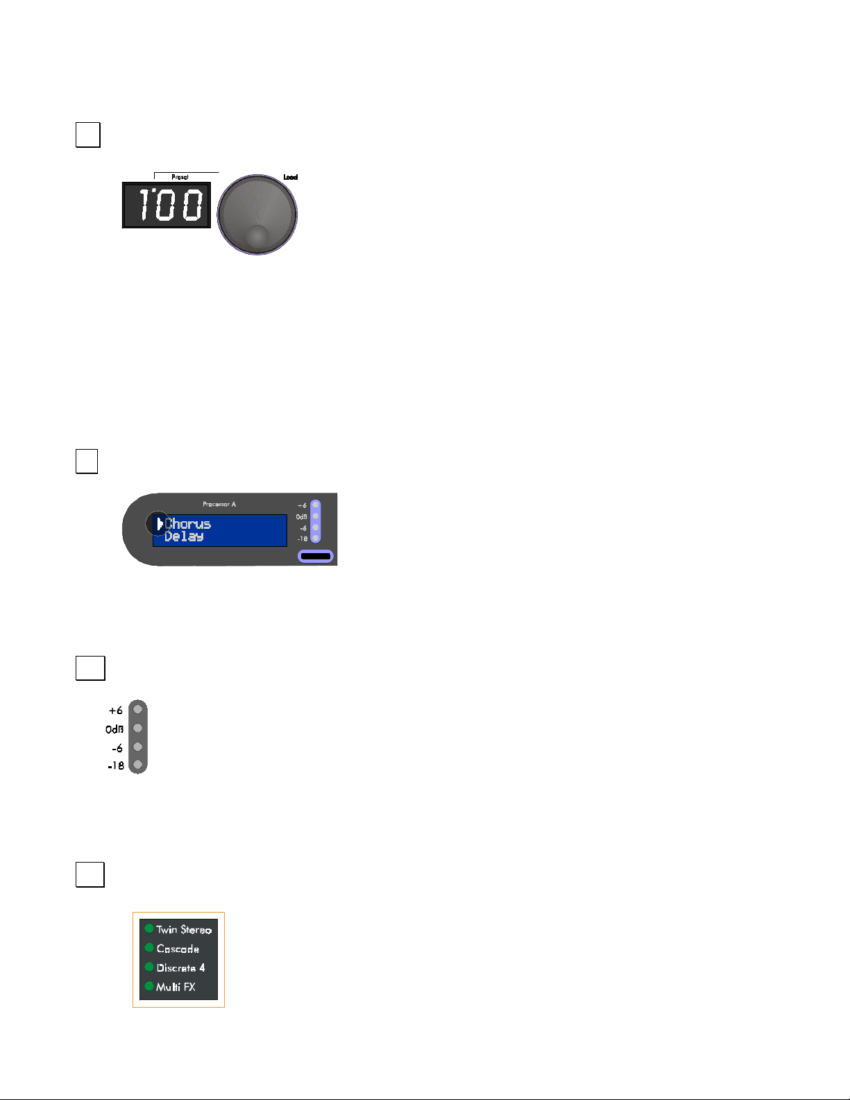
PRESET ENCODER / SWITCH
The Preset Encoder is used to change presets. As you turn it, the number in
the Preset Display changes, as does the information in both LCDs and the
Routing Display; these are showing you information about the new preset.
Notice that the light on top of the Preset Display is lit once you have turned the
encoder. This light indicates that you have not yet loaded the preset that you
currently are viewing, so you will not be hearing the effects or routing that you see on the front panel. To load
a preset, press the Preset Encoder.
When the MIDI/Util button is pressed, the Preset Encoder is used to scroll through the DMV-PRO’s global
parameters. LCDs (A) an d (B) will sho w a diff erent set of param eters . T o change a par am eter ’s value, turn its
corresponding encoder.
/
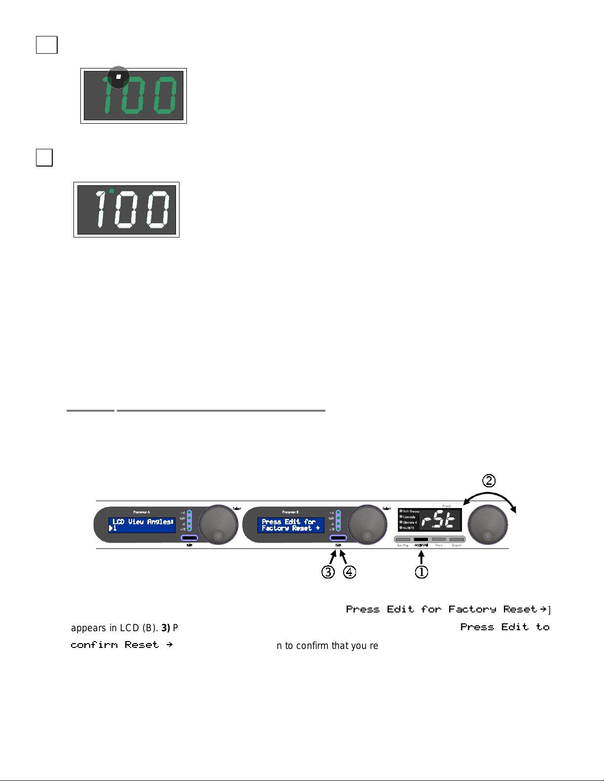
SELECTION ARROW
The Selection Arro w appears on the left s ide of an LCD and is used to
distinguish the active line. For exam ple, in the picture on the right, the
Selection Arrow indic ates that Chorus is the se lecte d effec t and it will be
affected by turning th e e nc oder or pres s ing the E dit button. To select th e
other line, press the s ame pr ocessor’s encoder. W hile ed iting, the Selecti on Arro w is used t o diff erentiate the
active parameter or value field.
0
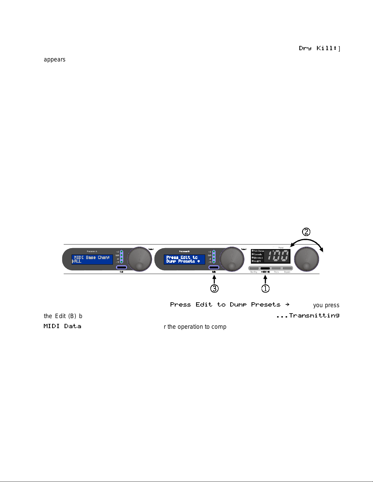
PROCESSOR (A) & (B) METERS
The meters show the level of signal entering each processor. They either display the level for the
current effect’s input (while e diting) or both com bined inputs of each pr ocessor (when in Preset m ode).
To optimize the levels entering the DMV-PRO, watch the +6 LED. If it is constantly lit, the digital
processor is getting too much input level and may clip; turn down the signal going to the DMV-PRO. For
maximum dynamic range, the m eter LE Ds s hou ld b e l it most of the time, with the +6 LED br ief ly flashing on transients
(high-energy bursts, such as loud snare drum hits).
1
ROUTING LEDS
The DMV-PRO has four signal-routing options: Twin Stereo, Cascade, Discrete 4, and
Multi FX. For a description and diagram of each routing, see page 26. Routings are
selected by repeatedly pressing the Routing button (see the above Routing Button
paragraph).
- 8 -
2
UNLOADED PRESET INDICATOR
When you turn the Preset Encoder to view presets, the DMV-PRO’s sound won’t
change until you press the Preset Encoder to load the preset. The Unloaded
Preset Indicator is a reminder that you are viewing an unloaded preset.
3
PRESET DISPLAY
The Preset Display shows 3 alphanumeric characters that correspond to the
current preset number, whether it’s presently loaded or not. When the Preset
Display is flashing a preset number, it is because you have entered Store mode
and pressing the Store button will overwrite the current preset number’s contents.
SPECIAL FUNCTIONS:
Restoring Presets to Original Factory Settings
The DMV-PRO can overwrite all stored presets with its original factory settings. This process is called a
Factory Reset.
WARNING: A Factory Reset erases all customized presets.
If you have saved some favorite programs, either sc r oll t hrough their parameters and write them down, or use
the MIDI Dump featur e to off- load your pres ets to a MID I storage d evice b efore im plementing a f actory res et.
(See page 11 for information on the DMV-PRO’s MIDI Dump.)
To perform a Factory Reset, follow these steps:
1)
Press the MIDI/Util button . 2) Turn the Pres et E ncoder unt il [
appears in LCD (B). 3) Press the Edit (B) button and not ic e th at LC D (B) is now flashin g [
0$11 #(2 %-0 "2-08 $1$2 :
0$11 #(2 2-
]
"-T%(0, $1$2 :
Edit is not pressed ag ain within 10 s econds, or if an y other butt on except for Edit is pressed, the DMV-PRO
will exit from Factory Reset mode with your former presets still intact.
]. 4) Press Edit ( B) ag ain to c onf irm that you re all y want to perf orm a Fact ory Res et. If
- 9 -

Dry Kill and Global Mix
Dry Kill and Global Mix are two related functions that allow you to quic kly alter the ratio of wet (processed)
and dry (unprocessed) sound com ing out of th e un it. Nor mally, the Mix parameter sets this r at io separately for
each preset, but by using Dry Kill or Global Mix, you can change these settings for all presets at once.
Dry Kill
when you are using the u nit with a m ixer. In a typica l mixing situat ion, a channe l’s fader contro ls the leve l of
the instrument patched into it. To add proces sing, a portion of the channel’s signa l is often sent to an eff ect
processor and the outp ut of the processor is patched into an other c h ann el. Now two faders control the overall
sound; the first fader s till c ontro ls the instr um ent’s lev el (a ll dr y) and the second one c ontro ls the DMV-PRO ’s
level (normally a m ix of wet and dr y signal) . As you can s ee, dr y sound app ears at b ot h faders and can resu lt
in an unbalanced m ix of s ounds. This is partic ularly not iceable when us ing a flan ger, p haser, or chor us sinc e
these effects are strongest with an equal mixture of both parts. Also, too much dry signal can result in a
diluted sound. By using Dry Kill to remove all dry signal from the DMV-PRO’s output, each fader will only
control one part of the sound and you will be able to blend the two easily at the mixing console.
With Dry Kill active, a preset’s Mix param eter sets the level of all sound com ing out of the DMV-PRO. For
example, with a Mix setting of 0, n o sound will com e out of the unit becaus e the dry part has be en disabled
and zero percent of the wet signal is now allowed to pass.
NOTE: If you are plugging directl y into the DMV-PRO and just listening to your instrum ent through the D MVPRO's outputs, do not set Dry Kill; use each preset’s Mix parameter to balance your sounds.
is used to remove all dry sound f r om the DM V- PRO ’s internal mix buss. One appl icati on for Dry Kill is
Global Mix
simple way to set each preset’s Mix param eter to a c ertain valu e. For example, if Global Mix is set to 50%, al l
presets’ Mix values will become 50% (h alf dry and half wet), regardless of individual Mix parameter settings.
This function is us eful when you qu ick ly want to auditi on al l pres ets with the s am e Mix le vel. T he c hange is n’t
permanent; as soon as you turn off Global Mix, the pres ets will re turn t o their orig inall y stored M ix l evels. You
can change and resave a preset’s Mix level with Global Mix active. You will hear Mix changes as you’re
making and saving t hem, but as soon as you switch to a different preset or back to the changed one, the
Global Mix value wil l again override the setting that you just made. Of course, when you tur n Global Mix off,
the saved Mix value will be the one that you hear.
Here’s a trick to quic k l y set se ver a l presets’ Mix parameters to a new value: Set Global Mix to whatever va lue
you desire, call up each of the presets you wish to change and individually save them (just press the Store
button twice). You don’t have to ed it anything! When you turn Global M ix off, the newly-saved presets will
have their Mix values set to whatever Global Mix was originally set to. All other presets will remain
unchanged.
is a function similar to Dry Kill, though it doesn’t n ecess aril y remove a ll dr y soun d. Globa l Mix is a
- 10 -
Setting Dry Kill and Global Mix:
To adjust Dry Kill or Global Mix, press the MIDI/Util button. Turn the Preset Encoder until [
appears on the top line of LCD (A). Turn Encoder ( A) to switch the bo ttom line of LCD (A) between ON and
OFF. If Dry Kill is on, th e effec t’s dry path is dis abled. If Dr y Kill is of f, dr y sound is a llowed to p ass and each
preset’s Mix control g over ns the r atio of dry an d wet s ignal. Also, if Dry Kill is of f, LCD (B) disp la ys the Globa l
Mix setting. By tur ning Encoder (B), you can tur n Global Mix OFF or set it to a perce ntage between 0 and
100.
Changing Dry Kill or Global Mix takes effect immediately and does not ha ve to be saved. To exit MIDI/Util
mode, press the MIDI/Util button.
NOTE: The Dry Kill state is retained when turning the DMV-PRO on and off. The Global Mix state, however, is
not retained; the unit defaults to each preset’s stored Mix level when turning power on (i.e., Global Mix OFF).
MIDI Dump
By performing a MIDI Dump, you can save the DMV-PRO’s presets and MIDI Map to an external MIDIrecording device. You can even directly transfer the presets and the MIDI Map from one DMV-PRO to another
08 (++A
]
one with a MIDI cable.
To perform a MIDI Dump, press the MIDI/Util button.
Turn the Preset Enco der until L CD (B) reads: [
the Edit (B) button, the preset information will be sent and both LCDs will read: [
2
NOTE: Individual pr esets and the MIDI M ap can be dumped or loaded separ ately if the operation is ini tiated
by an external MIDI device such as a s equencer or an ext ernal controller . See page 51 for m ore inform ation
on the DMV-PRO’s MIDI implementation.
]. It may take a few seconds for the operation to complete.
0$11 #(2 2- 3,. 0$1$21 :
0 T1,(22(T&
]. When you press
- 11 -
DMV-PRO REAR PANEL CONNECTIONS
Despite the DMV-PRO ’s sophis tication, i t’s eas y to interf ace the unit with other eq uipment. All inputs and outputs ar e
located on the rear panel. Standard ¼” inputs and outputs make patching simple.
Note: For best audio quality, always use high-quality cables.
The DMV-PRO is des igned f or l ine le vel or inst rum ent oper ation. We don’t recommend pl uggin g m ic rophones dir ectl y
into the processor. Ins tead, either use a pr eamp, a mixer, or an am p’s preamp section to f irst boost the mic’s level ,
then use the effect s loop output or re verb send. Hi gh signal le vel from a pream p or eff ects loop assures an optim um
signal-to-noise ratio in the DMV-PRO, keeping hiss and distortion to a minimum.
$
POWER JACK INPUT
An external AC adapter powers the D MV-PRO. Plug the ada pter into this jack and th en into a power outlet.
Only use the adapter that came with the DMV-PRO. If the adapter ever becomes damaged, immediately
discontinue use.
%
MIDI IN & MIDI OUT
The MIDI In jack enables you to “talk” to the DMV-PRO fr om an external source such as A R T’s X-11 or X - 15
Ultrafoot, an outboard sequencer , or a com puter equipped with MIDI ports a nd associate d software. Use this
jack for receiving program change, continuous controller, note, and system exclusive messages.
Use the MIDI Out jack for performing a MIDI data dump. It connects to any external device capable of
recording MIDI data and allows the DMV-P RO to off -load the c onte nts of its m emor y. The MIDI O ut jack does
not act as a MIDI Thru, so the DMV-PRO should be placed at the end of your MIDI chain.
- 12 -

&
OUTPUTS #1–4
All four Outputs are single-en ded (unbalanced) ¼” j acks with low impedanc e. A preset’s routing d etermines
the use of each Output jack. For example, Cascade and Multi FX Routin gs do not us e O ut puts # 3 an d #4. For
more information on t he different c onfigurations of the DMV-PRO’s inputs and outpu ts, see p age 26 and the
tutorial starting on page 14.
'
OUTPUT LEVEL SWITCH
The Output Level sw itch is used for matching the D MV-PRO’s output level to your system . Matched signal
levels are important for controlling the amount of distortion present in the final signal. Too little signal results in
a disproportionate amount of noise, while too much signal sounds distorted and gritty. The Output Level
switch has two pos itions: in (instrum ent level) and out (line le vel). Be sure to check your other equipment’s
manual for hints on setting its appropriate input levels.
NOTE: The Output switch’s setting is global, meaning that it always affects the DMV-PRO’s output level,
regardless of which preset is engaged.
(
INPUTS #1–4
All Inputs are single- ended (unbalance d) ¼’ jacks with hig h impedance. As wit h the Output jack s, a preset’s
routing determines the use of eac h Input j ack. For exam ple, Cascade and Stere o Routings do not us e Inp uts
#3 and #4. For more inf ormation on the different conf igurations of the DMV-PRO’s in puts and outputs, see
page 26 and the tutorial starting on page 14.
If any Input (except #1) does not have a plug ins erted, it will automatically tak e its signal from the closest,
lower-numbered, input jack that has a plug inserted. For ex ample, if a ¼” pl ug is only inserted into Input #1,
then Inputs #2, #3, and #4 will also use the signal from Input #1.
)
INPUT LEVEL SWITCH
The Input Level switch is s im ilar to t he Ou tput Le vel s witc h, bu t is us ed for m atching th e lev el of the inc om ing
signal to the DMV-PRO . The Input Level switch has two positions: in (instrument level) and out (line le ve l) . Be
sure to check your other equipment’s manual for hints on setting its appropriate output levels.
NOTE: Like the Output Le vel switch, the Input Level switc h’s setting is global, meanin g that it alwa ys affects
the DMV-PRO’s input level, regardless of which preset is engaged.
- 13 -
TUTORIAL
The best way to understand the DMV-PRO is just to jum p in and edit som e presets. It doesn’t take long and
you’ll see how eas y editing is due to the DMV-PRO ’s intuitive layout. T his section consists of four tutoria ls:
Starting from Scratch and Changing Effects, Editing Effect Parameters, MIDI
After you finish the tutorials, chec k out the sect ion entit led
26, for a complete list of each effect’s parameters and parameter ranges.
INTRODUCTION
The DMV-PRO contains f our DSP eng ines and four s eparate inpu t and outpu t channe ls. T ypically, an e ngine
processes one individ ual channel of audio. T wo engines can be com bined into stereo grou ps with separate
audio channels and linked control parameters. Two stereo groups can be run in series to create multiple
effects and there’s even a special routing that runs two mono engines and one stereo group in series to
create even longer multi-ef fect chains. By the way, each engine or engine group has its own EQ and delay
section and many c lasses also contain a dynamics s ensing section, so effect chains can actua lly be quite
long. Engines #1 and #2 are al ways contro lled b y the DM V-PR O’s Proces sor ( A) sect ion an d Eng ines #3 and
#4 are always controlled by Processor (B). Resource distribution between the inputs and outputs is
automatically handled b y our proprietary Dynam ic Engine Alloc ation (DEA™) tec hnology. DEA allows for the
following creative signal-routing options:
, and
Advanced Applications
The DMV-PRO ’s Adjustable Parameters
:
, on page
.
Twin Stereo
Twin Stereo routing contains two effect-processors
with two linked engines each. The result is two truestereo effects. Each channel’s audio remains
independent, but the effec t parameters of each group
are linked to create stereo proces sing. The first eff ect
(Inputs, Outputs, and Engines #1 and #2) is edited in
Processor (A) and th e second effect (Inputs, Outputs,
and Engines #3 and #4) is edited in Processor (B).
- 14 -
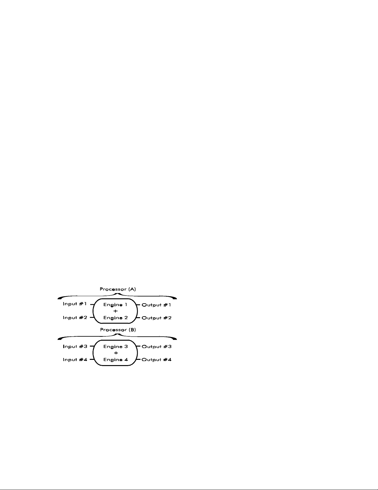
Cascade
Discrete 4 (mono)
Cascade routing also has two effects with two
linked engines, but the output of the first group is
fed into the second. In t his routing, you have two
stacked, true-stereo effects. Only Inputs and
Outputs #1 and #2 are used. The first effect
(Engines #1 and #2) is edited in Processor (A),
and the second effect (Engines #3 and #4) is
edited in Processor (B).
In Discrete 4 routing, each engine se parately processes one
channel of sound and is just like having four mono effects.
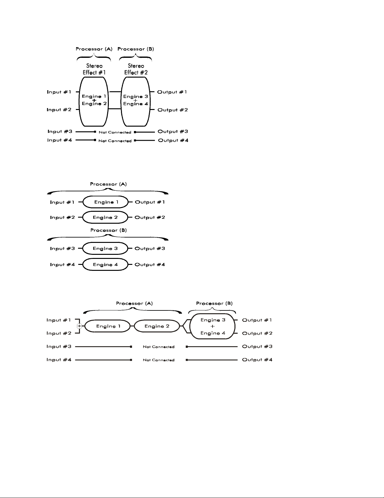
Multi FX
Multi FX routing com bines the signal fr om Inputs #1 and #2 and runs it in series through Eng ines #1 and #2.
The signal is then sp lit and fed to both inputs of linked engines #3 and #4, which are running in true-stereo.
The signal from Engine #3 is s ent to Output # 1 and the s ignal f rom Engine #4 is s ent to Out put #2. Inp uts and
Inputs and Outputs #1–4 correspond to Engines #1–4.
Engines #1 and #2 are edited in Processor (A) and Engines
#3 and #4 are edited in Processor (B).
Outputs #3 and #4 are not used. Processor (A) controls the two mono effects (Engines #1 and #2) and
Processor (B) controls the true-stereo effect group (Engines #3 and #4).
NOTE: See page 26 for more information on the DMV-PRO’s versatile routing configurations.
- 15 -
 Loading...