

Page 1

General Overview
The Model 310 is a fourth order Linkwitz-Riley electronic crossover. This
unit may be used in two modes of operation:
Stereo 2-Way -or- Mono 3-Way
The 310 crossover splits the frequency of an input signal into two (when
used as a 2-Way crossover) or three (when used as a 3-Way crossover)
separate signals which may then be sent to amplifiers or other signal processing equipment in a sound system.
Power Connections
The 310 has an internal power supply which is designed to operate from
95 to 130VAC at 50/60Hz or from 190 to 250VAC at 50Hz. Power consumption is 12 watts. Make sure the line voltage switch is set to the proper setting before plugging the unit into a mains socket.
Never operate this piece of equipment with the ground pin removed. If the
cord becomes cracked or broken, discontinue use until you can have it
replaced.
Installation
The 310 occupies a 1U rack space and is intended for installation in standard 19” equipment racks. Its depth is 8.5” and weight is 4.5lbs (2.5kg.)
* Caution: The following must be observed to prevent malfunctioning and/or possible equipment damage.
1. Before plugging in the 310 into the main AC line, make sure that all of
the equipment following the crossover outputs is turned off or all of the
inputs are turned down.
2. The unit should only be turned on after it has been established that the
main AC line is supplying the correct voltage.
3. Never change the frequency range switches (from x10 to x1 posi-
tion - or vice versa) with the crossover passing audio signals.
Transients can result and speaker damage is possible.
4. Keep the 310 away from excessive moisture.
1
Page 2
Note: the High 1 and the Input 2 jacks are not used when configured for
three-way.
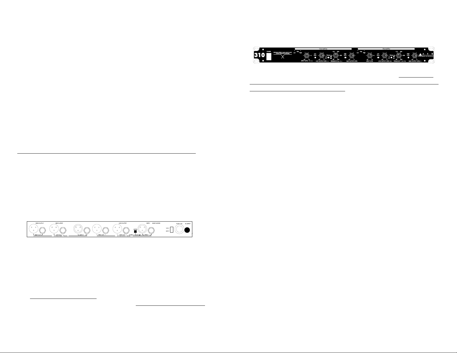
Front Panel
Power Switch
The power switch applies and removes power to the 310. Make sure all
equipment after the 310 is either off or the volumes are turned all the way
down before turning on or off the 310.
Clip Indicators
Separate High and Low clip indicators are provided for each frequency
band in the 310. These indicators will light at approximately 3dB before
clipping occurs in any stage of the 310. If these indicators light, you are
overloading the 310. Either turn down the input controls on the 310 or
turn down the output level of the piece of equipment in front of the 310
(i.e. mixer, equalizer or other piece of processing equipment.).
Input Level
An Input Level control is provided on each channel of the 310. If you are
using the 310 as a mono 3-way crossover, the Input control on the far left
is the only one used. The input level control should be set at its “0” marking in most cases. Adding or reducing gain should only be done to make
up for deficiencies in another part of the system.
Mute Switches
Mute switches are provided for each output on the 310. These are intended for use when setting up your system and testing either the crossover
frequency point or the separate cabinets (and amplifiers) they are feeding. These switches allow you to isolate a specific frequency output on a
specific channel for fine-tuning or trouble-shooting. It is not recommended
that you mute or activate any frequency band during normal usage.
Levels should be turned down while the mute switches are either activated or de-activated.
High and Low Output Levels
Each channel of the 310 has a High and Low Output Level control. These
controls are used to set the output levels to the next piece of equipment
connected to the 310. (In most cases this would be power amplifiers.)
There is no gain associated with these controls - only attenuation. In most
cases you will use the 310 with the output controls set fully clockwise (at
their “0” setting.) If you find that you are overdriving the inputs of your
3
Stereo 2-Way and Mono 3-Way Operation
A stereo 2-way sound system is typically set up as follows: Separate
high frequency (horn or full range) and low frequency (bass or sub) cabinets are used for each side (left and right) of the sound system. The
crossover is used to split each side of the stereo signal into two frequency bands which will feed separate power amplifiers. This arrangement
accomplishes two things: it allows the proper frequencies to be routed to
the proper speaker cabinets and it allows the amplifier to produce power
more efficiently to the speakers it is driving.
A 3-way sound system is typically set up as follows: Separate high
frequency (horn), mid frequency (mid or full range) and low frequency
(bass or sub) cabinets are used for each side (left and right) of the sound
system. The crossover is used to split each side of the stereo signal into
three frequency bands which will feed separate power amplifiers. This
arrangement accomplishes two things: it allows the proper frequencies to
be routed to the proper speaker cabinets and it allows the amplifier to
produce power more efficiently to the speakers it is driving.
You will need two 310 crossovers if you’re three-way system is stereo.
It is very important that you use caution when selecting the
crossover points for any system. Refer to the documentation that
came with your speaker cabinets for information on their proper frequency ranges. This is especially important for high frequency
horns; damage may occur from sending lower frequencies than
specified into the drivers!
Rear Panel
Input and Output Connections
The XLR input and output connections are balanced and follow the AES
standard for wiring: Pin 1 = Ground, Pin 2 = Hot (+), Pin 3 = Cold (-). The
input and output 1/4” connectors are unbalanced. The 1/4” connections
are: Tip = Hot (+) and Ring = Cold (-).
The input and output jacks are labeled for stereo 2-way and mono 3-way
use. For stereo two-way usage, follow the connections labeled one (1)
and two (2). Example: Input 1, Low 1, High 1. For mono three-way usage,
follow the connections labeled Input, Low, Mid, High.
2
Page 3

3-way front-panel controls (reading from left to right):
Channel One controls
Input Level - The mono input level control
Low Mute - Low output mute
Low Output Level Control - The low output level control
Frequency Range Switch and Control - low/mid crossover point
High Mute -
not used
High Output Level Control -
not used
Channel Two controls
-
Input Level -
not used
Low Mute - Mid output mute
Low Output Level Control - The mid output level control
Frequency Range Switch and Control - mid/high crossover point
High Mute - High output mute
High Output Level Control - High output level control
Signal Flow
The following is just a guideline. In most situations, the crossover is the
last piece of equipment in the signal chain before the power amplifiers.
Signal flow is as follows: From the output of the mixer to an equalizer
(Sometimes, for system protection, a limiter is placed between the mixer
outputs and the equalizer, or after the equalizer.) From the equalizer to
the crossover. From the crossover to the power amplifiers. From the
power amplifiers to the speaker cabinets.
Here are some tips to help you with your initial setup.
2-way set up:
1. Set all the levels controls to their full counter-clockwise position (off.)
2. Connect the outputs of your mixer (or equalizer) to the inputs of the
310. If stereo, Channel One is Left.
3. Connect the Low output of Channel One to the power amplifier power-
ing the low frequency cabinets (left).
4 . Connect the High output of Channel One to the power amplifier pow-
ering the high frequency cabinets (left).
5. Repeat for the right side of the system (Channel Two).
6. Set the crossover frequency for both channels (they should be the
same if your PA cabinets are the same).
7. With the power amplifier volume controls turned all the way down, turn
on all equipment in the system.
8. With a program source running through the system, turn up the power
amplifier volume controls and slowly turn up the crossover’s Input
controls. Check for clipping.
9. Turn up each of the crossover’s output level controls while checking
5
amplifiers, you can turn down the output levels feeding the amplifier.
Additionally, you can use the output level controls to balance the level
between the highs and lows in your system.
Range Switch
The Range switch is used to set the frequency range of the Frequency
control. In its “out” (x1) position the frequency range is variable from 80Hz
- 920Hz, as is printed on the panel. In its “in” (x10) position the frequency
range is variable from 800Hz - 9200 kHz.
When used as a 2-way crossover, the Range switch will probably be used
in its “out” position.
When used as a 3-way crossover the Range switch for Channel One
(now the low/mid crossover point) will probably be used in its “out” position while the Range switch for Channel Two (now the mid/high crossover
point) will probably be used in its “in” position.
Never change the frequency range switches (from x10 to x1 position
- or vice versa) with the crossover passing audio signals. Transients
can result and speaker damage is possible.
Frequency Control
Each channel of the 310 has a Frequency control which sets the
crossover point for the high and low frequencies. All frequencies below
the set frequency will be sent to the Low output and all frequencies above
the set frequency will be sent to the High output.
When used as a 3-way crossover the Frequency control for Channel One
is used to set the low/mid frequency point. The Frequency control for
Channel Two is used to set the mid/high frequency point.
Operating Instructions
The 310 crossover’s intended use is to split the frequency of the input
signal into two (when used as a 2-Way crossover) or three (when used as
a 3-Way crossover) separate signals which are then sent to amplifiers in
a sound system.
When used as a 3-way crossover you must follow the labeling for 3-way
operation of the controls.
4
Page 4

Power: 95-130VAC, 50/60Hz, 3 VA
190-250VAC, 50Hz, 3 VA
Size: 1.75”H x 19” W x 8.5” D
Weight: 4.5lbs. (2.5kg)
Warranty and Service Information
Limited Warranty
Warranty service for this unit will be provided by Applied Research and
Technology, Inc. in accordance with the following warranty statement.
Applied Research and Technology, Inc. (AR T) warrants to the original
purchaser that this product is free from defects in workmanship and
materials for a period of one year from the date of purchase. A R T will,
without charge, repair or replace, at its option, defective product or component parts upon prepaid delivery to the factory service department or
authorized service center, accompanied by proof of purchase date in the
form of a valid sales receipt.
EXCLUSIONS: This warranty does not apply in the event of misuse or
abuse of the product or as a result of unauthorized alterations or repairs.
This warranty is void if the serial number is altered, defaced or removed.
A R T reserves the right to make changes in design and make additions
or improvements upon this product without any obligation to install the
same on products previously manufactured.
A R T should not be liable for any consequential damages, including without limitation damages resulting from the loss of use. Some states do not
allow limitation of incidental or consequential damages, so the above limitation or exclusion may not apply to you. This warranty gives you specific
rights and you may also have other rights which vary from state to state.
For units purchased outside the United States, service will be provided by
an authorized distributor of AR T products.
Service
The following information is provided in the unlikely event that your unit
requires service. Use this procedure to return units in the United States
only. For service outside the United States, please contact your authorized
A R T distributor.
1) Be sure the unit is the cause of the problem. Check to make sure the
unit has power supplied, all cables are connected correctly, and the
7
each individual output for sound and performance.
3-way set up:
1. Set all the levels controls to their full counter-clockwise position (off.)
2. Connect the output of your mixer (or equalizer) to the Channel One
(mono input in mono 3-way mode) input of the 310.
3. Connect the Low output of Channel One (Low) to the power amplifier
powering the low frequency cabinet.
4. Connect the Low output of Channel Two (Mid) to the power amplifier
powering the mid frequency cabinet.
5. Connect the High output of Channel Two (High) to the power amplifier
powering the mid frequency cabinet.
6. Set the low/mid crossover frequency with the Low/Mid Frequency
Control.
7. Set the mid/high crossover frequency with the Mid/High Frequency
Control.
8. With the power amplifier volume controls turned all the way down, turn
on all equipment in the system.
9. With a program source running through the system, turn up the power
amplifier volume controls and slowly turn up the crossover’s Input
control. Check for clipping.
10. Turn up each of the crossover’s output level controls while checking
each individual output for sound and performance.
Specifications:
Crossover Frequency Ranges: 80Hz to 920Hz (x1)
800Hz to 9200kHz (x10)
Filter Type: Fourth-order Linkwitz-Riley
Input connections: Balanced XLR and unbalanced 1/4”
XLR pin 2, 1/4” tip = Hot (+)
Impedance: 20k Ohms
Max. Input level: +13dB
Output connections: Balanced XLR and unbalanced 1/4”
XLR pin 2/ 1/4” tip = Hot (+)
Impedance: 150 Ohms
Max. Output level: +21dBu @ <0.05% THD 20-20kHz
Maximum Gain: +4dB
Frequency Response: 10Hz to 20kHz, +0/-1.5 dB
THD + Noise: <0.05% (20Hz to 20kHz)
Hum and Noise: <-95dB (20Hz to 20kHz)
Av=0dB, fc=800Hz
Signal to Noise Ratio: 118dB
6
Page 5

9
cables themselves are in working condition.
2) If you find the unit to be at fault, write down a description of the problem, including how and when the problem occurs.
3) Call the factory for a Return Authorization (RA) number.
4) Pack the unit in its original carton or reasonable substitute. The pack-
ing box is not recommended for a shipping carton. Put the packaged unit
in another box for shipping. Print the RA number clearly under the
address.
5) Include with your unit: a return shipping address (we cannot ship to a
P.O. Box), a copy of your purchase receipt, a daytime phone number and
the description of the problem.
6) Ship the unit to:
Applied Research and Technology, Inc.
215 Tremont Street
Rochester, NY 14608
Atten: Repair Department
R.A.# _______________
7) Contact our Customer Service department at 716/436-2720 for your
Return Authorization number or questions regarding your repair.
Customer Service hours are Monday through Friday 8:30AM to 4:30PM
Eastern time.
8
Page 6

APPLIED RESEARCH AND TECHNOLOGY, INC.
215 TREMONT STREET
ROCHESTER, NEW YORK 14607 USA
716-436-2720 voice
716-436-3942 fax
Internet
artroch@aol.com
artroch@cis.compuserve.com
World Wide Web: http://www.artroch.com
#310
Precision Stereo 2-Way/ Mono 3-Way
Crossover Network
310-5004-102
Model #310
Precision Stereo 2-Way/Mono 3-Way
Crossover Network
User’s Guide
 Loading...