

Page 1
Installation and maintenance instructions
Xpelair Wholehouse
Heat recovery units
Xcell 300/400
Keep these instructions with the heat recovery unit
Page 2

Index
1. General
1.1 Configuration
2. Installation
2.1 Regulations
2.2 Mounting the unit
2.3 Connecting the ductwork
2.4 Positioning the valves
2.5 Condensation drain
2.6 Speed control
2.7 Fire alarm
2.8 Power Supply
2.9 Bypass
3. Commissioning the system
3.1 Setting the air flow
3.2 Fan speed adjustment
4. Unit specification
4.1 Performance graphs
4.2 Fan curves
4.3 Performance data
5. Maintenance
5.1 User maintenance
5.2 Specialist maintenance
6. Commissioning record
7. Guarantee
7.1 Guarantee
7.2 Liability
Page 3

1. General
Thank you for purchasing an Xpelair Xcell Wholehouse heat recovery unit. We have paid a
great deal of attention to the design of this unit and have only used high quality,
recyclable materials in its manufacture which is powered by energy efficient EC/DC
motors.
This system is designed to run 24 hours a day.
The Xcell unit is the centre of a balanced supply and extract ventilation system. Other
products available from Xpelair include, flexible, flat and slim ductwork, and a 3-speed
switch.
In certain circumstances it is possible to connect a fan-less kitchen cooker hood into the
system.
This guide is intended as a reference manual for the fitter, so that he can install and
correctly maintain the unit. Please read this booklet thoroughly before installing the unit.
In the unlikely event that you have to contact our offices please quote the type of unit,
order number, and date of manufacture.
1.1 Configuration
The Xcell unit has been designed for extracting stale air from a dwelling and replacing it
with fresh filtered air.
The Xcell units are available in 4 configurations
1. Xcell 300; duct connections to the house on the right and external duct
connections on the left.
2. Xcell 300BP; duct connections to the house on the right and external duct
connections on the left.
This unit is complete with an automatically regulated by pass damper.
3. Xcell 400; duct connections to the house on the right and external duct
connections on the left.
4 Xcell 400BP; duct connections to the house on the right and external duct
connections on the left
This unit is complete with an automatically regulated by pass damper.
Page 4
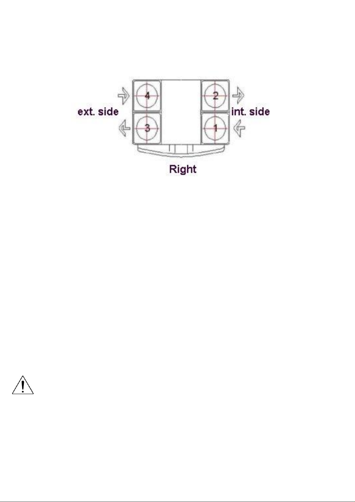
Duct connections
1 = Extract internal
2 = Supply internal
3 = Exhaust external
4 = Supply external
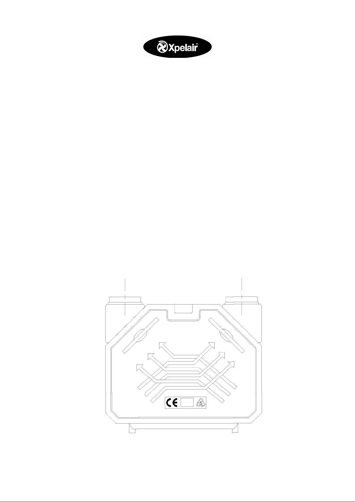
2 Installation
View - looking at the top of the unit
The Xcell unit must be placed in a frost-free space.
Close to the unit there must be a 220/240 Volt fused spur (with earth), a suitable
connection for the condensate drain and sufficient space to connect the duct runs to the
heat recovery unit.
If the unit is to be fixed to a wall/partition the unit must be installed using the hanging
bracket provided. The wall should be structurally rated to accept a weight of 200Kg per
square meter.
The unit must be installed horizontally (with the spigots at the top). A spirit level should
be used to make sure that it is straight.
Enough space should be left to allow a significant slope for the condensate drain to
ensure correct evacuation of the water.
A minimum space of 800 mm is needed at the front of the unit to open the access door and
change the filters.
Connect power supply after assembling the ducting!
2.1 Regulations
Where applicable installation of the unit must comply with all local regulations including,
building, electrical and sewerage connections.
Page 5

2.2 Mounting the unit
The Xcell unit can be placed on a floor or attached to a
wall with the hanging bracket provided. If floor
mounted, assemble the unit so that sound and vibration
transfer is avoided and there is sufficient height for the
condensation drain. If wall mounted secure the unit by
using the bracket provided. The wall or partition should
be at least 100 mm thick.
Unpack the unit and place it on the ground. Unbolt the
metal lid on the top of the unit and remove it. Turn the
nut separately and remove the hanging bracket. Fix the
hanging bracket to the wall/partition. Use a spirit level to
make sure the bracket is level.
2.3 Connect the ducting
To avoid condensation ductwork inside the loft space must be insulated.
It is recommended that that insulated acoustic flexible ducting be used with a minimum
length of 1 metre on the external sides of the unit and a minimum length of 500 mm on
the internal side.
Where possible the air intake to the building should be sited in a sheltered area.
Supply and extract to and from the house can be through roof terminals or louvres.
To make sure there is no re-circuiting of polluted air a minimum of 2 metres should be
allowed between the supply and discharge terminals.
To allow free airflow through out the house a gap beneath the doors must be provided
(or grilles put at low level in the doors)
2.4 Positioning extract and supply valves
Extract grilles should be placed in all wet rooms in accordance with the Building
Regulations and supply valves in all the heated rooms. Extract grilles should be sited
close to the main source of humidity.
Care should be taken not to create drafts in sensitive areas of the house e.g. bedrooms,
etc.
2.5 Connect condensation evacuation.
The condensation drain is in the lower part of the unit.
In a Right-handed unit the left hose connection must be used.
The hose fitted to the condensate drain must have an internal diameter of 12 mm and a
minimum length of 1.5 metres.
2.5.1 The drain should run through a secondary trap before being discharged though the
eaves of the house or into the waste water systems (check local regulations).
Page 6

2.6 Speed control
The cable between the Xcell 300/Xcell 400 and the 3-speed switch must be 4-core with a
minimum thickness of 0.14 mm.
The connections are to a connector under the top plate of the unit. To make the
connections easier the plug is removable.
When replacing the unit top plate it is important to make sure there are no air leaks, as
this will affect the performance of the product.
The cables must be connected to the correct terminals or the unit will run at incorrect
speeds or the unit may be damaged.
For correct connections of the 3-position switch see the wiring diagram.
The speed control is low voltage and must not be connected directly to a 230
volts power supply.
2.7 Fire alarm contact
It is possible to connect a volt free fire alarm contact to the unit.
The fire alarm contact must be connected to the P and BM of the 5pole connector. If the
contact is made, the supply fan will stop and the extract fan will run at maximum speed.
2.8 Power supply
The unit must either be wired to a suitably earthed 230/240-volt single-pha se 50 Hz fused
spur or to a standard 3 pin 13 -amp socket.
The electric installation must be in accordance with the requirements of the local electrical
regulations.
Page 7

2.9 By-pass
The Xcell unit with by-pass is factory installed and programmed by Xpelair. There is an
extra bypass circuit in the connection box, and one in the by-pass cassette. These circuits
automatically control the opening and closing of the by -pass. The room and outside
temperatures are detected by two sensors, which are fitted inside the unit.
The temperature sensors have been fitted to the bypass module. The sensor fitted to the
lower part is the room temperature sensor (red) and the sensor to the upper part is the
outside air temperature sensor (blue).
By-pass open when:
The room temperature is above 20 °C. (LED 1 = on) and
the outside temperature is under the room temperature (LED 2 = on) and
the outside temperature is above 15 °C (LED 3 = on).
By-pass closed when:
The outside temperature is above the inside temperature or
The outside temperature is below 15 °C or
The inside temperature is below 20 °C.
Temp 1 = room temperature sensor.
Temp 2 = outside temperature sensor.
LED 1 = room temperature.
LED 2 = difference between outside and
inside temperature.
LED 3 = outside temperature.
LED 4 = By-pass closed.
LED 5 = By-pass open.
LED 6 = By-pass active.
LED EXT = for connection to a remote
LED (not supplied).
3. Commissioning the system
3.1 Setting the air volume
The unit is provided with 3-step regulation. The supply and extract fan run
independently of each other and are individually programmable.
3.2 Fan speed adjustment (Figure 1)
The extract fan can be adjusted with the 3 red potentiometers that are marked AV and the
supply fan by those marked TV.
When the speed settings are changed the system must be rebalanced ensuring that the
supply and extract air flow are similar. This is to protect the heat exchanger from any
possible damage.
Page 8

Standard settings for the Xcell 300 are 100, 150 and 300 m³/h
Standard settings for the Xcell 400 are 100, 200 and 350 m³/h
Figure 2: LED panel
A Power supply
B Frost protection
C Extract fan on
D Supply fan on
E Bypass open (optional)
F Pos 1: Set back (holidays etc.) (1)
G Pos 2: Standard setting (2)
H Pos 3: Boost (3)
Page 9

4.Technical specifications
4.1 unit specification
Figure 3: Dimensions Xcell unit
Dimensions (W x d x h)
Diameter ducting
Weight
Temperature efficiency
Power supply
Fuse in unit
Protection class
Filter class
: 740 x 600 x 540 mm
: Ø150/160 mm (Xcell 300) or Ø 180 mm (Xcell 400)
: 32 kg
: 90%
: 230 V 50 Hz
:2,0A
:IP20
:G3
Page 10

4.1.Performance and electrical data Xcell 400
Qv [m³/h] Pst[Pa] U[V] I [A] P[W] cos phi [-]
400 147 230 1,52 241 0,69
377 150 230 1,42 223 0,68
347 145 230 1,20 189 0,68
337 100 230 1,02 155 0,66
299 110 230 0,88 133 0,66
265 88 230 0,70 103 0.64
230 50 230 0,53 75 0,62
169 50 230 0,38 49 0,56
98 45 230 0,28 31 0,48
4.2. Fan Curves
Xcell 400
Page 11

Electrical data Xcell 300
4.3 Performance Data
Qv[m³/h] U[V] I [A]
P[W]
cos phi [-]
200 303 230 1,17 185 0,69
251 257 230 1,15 177 0,67
200 241 230 1,00 153 0,66
150 262 230 0,87 133 0,66
150 201 230 0,69 101 0,64
101 181 230 0,50 71 0,61
100 103 230 0,37 47 0,55
45 98 230 0,28 31 0,48
5 Maintenance
5.1 User maintenance
Clean the filters (with a vacuum cleaner) twice a year and the air vent grilles wiped clean
every 6 months.
The two filters can be taken out by the handgrips
.
5.2 Specialist maintenance
The heat exchanger must be removed and cleaned every 3 years.
Page 12

Remove the filters. Unscrew the front panel (two screws). Remove the cover plate.
Where there is a by-pass, disconnect the plugs on the board. The heat exchanger is now
accessible. Remove the four rubber gaskets and take the heat exchanger out.
Clean the exchanger, with warm water and a normal
soap (no solvents).
Then rinse with warm water.
Reassemble the unit (reverse of dismantling) making
sure all components are correctly refitted ensuring there
are no air leaks.
If the fans are dirty they must be cleaned with a brush
and vacuum cleaner.
6. Commissioning Records
Type plate:
Type
Bypass
Order number
Date
Valves Extract
Required
Normal 2
Kichen
Bathroom
Toilet
Total:
Measured
Normal2
Measured
Boost 3
Measured
Set back1
Type
valve
Supply
Living room 1
Living room 2
Living room 3
Bedroom 1
Bedroom 2
Bedroom 3
Total:
Required
Normal
Pos2
Measured
Normal
Pos2
Measured
Boost
Pos3
Measured
Set back
Pos1
Type
valve
Setting
valve
Setting
valve
Page 13

7.1 Guarantee
Do’s and don’ts
• Do read all the instruction leaflet before commencing installation.
• Do install each fan with a double pole isolating switch.
• Do make sure the mains supply is switched off before attempting to make electrical
connections or carry out any maintenance or cleaning
Guarantee
Customers outside UK – see international below.
• UK: The fan is guaranteed against defects for 5 years from the date of purchase.
• Please keep your purchase receipt.
• If you have any problems, contact Xpelair’s Head Office at the address shown below.
Technical advice and service
Customers outside UK – see international below.
UK: Xpelair have a comprehensive range of services including:
• Free technical advice help-desk from Engineers on all aspects of ventilation
• Free design service, quotations and site surveys
• Service and maintenance contracts to suit all requirements.
Please ask for details:
• By telephone on Techline:+44 (0) 8709 000430
• By fax on Techfax:+44 (0) 8709 000530
• At the address below
International
• Guarantee: Contact your local distributor or Xpelair direct for details.
• Technical Advice and Service: Contact your local Xpelair distributor
7.2 Liability
The Xcell unit has been designed and manufactured for use only as part of a
"balanced ventilation system". If the Xcell unit is used in any other way this may
lead to damage of the Xcell unit. In such circumstances the guarantee will be void
and Xpelair will not accept any responsibility.
Do not use a motorised cooking hood on this system.
Applied Energy Products Ltd
Morley Way
Peterborough
PE2 9JJ
t 01733 456789
f 01733 310606
www.applied-energy.com
Xpelair is a registered trademark of Applied Energy Products Limited.
Applied Energy Products reserve the right to alter product specifications
or appearance without prior notice. All finishes and diagrams in this
booklet are as accurate as printing processes allow.
 Loading...