

Page 1
Xcell 270 Longlife
DC wholehouse heat recovery unit
Installation and maintenance instructions
Page 2

Xpelair Xcell 270 Longlife DC wholehouse heat recovery unit – Xcell 270, Xcell
270BP
Please leave this leaflet for the benefit of the user.
The Xcell 270 range is subject to continuous improvement. Xpelair reserves all rights to make alterations
at any time without prior notice.
IMPORTANT!
Please read these instructions carefully before attempting installation, and retain for future
reference.
• This appliance is intended for connection to fixed wiring
• Check that the electrical rating shown on the unit matches the mains supply
• All installations must be supervised by a qualified electrician
• Installations and wiring must conform to current IEE Regulations (UK), local or appropriate
regulations (other countries)
• The appliance must be sited away from direct sources of heat and not operated in ambient
temperatures in excess of 40°C
Inspection Upon Delivery
Always check the following.
• Correct product has been delivered.
• Product type identification plate.
• That the unit is undamaged.
Positioning the unit
Always position the Xcell 270 unit vertically and use a spirit level, this will ensure a correct and level
position of the condensate water sump.
The appliance must be sited away from direct sources of heat and not operated in ambient temperatures in
excess of 40°C
The appliance must be sited away from any source of water and out of reach of any person using a fixed
bath or shower.
If a grille associated with this appliance is sited in a room containing a fuel burning appliance the installer
must ensure that air replacement is adequate for both appliances.
The external grilles associated with the unit must be sited at least 600mm away from the flue of a fuel
burning appliance.
Do not site any associated internal grille in the vicinity of excessive levels of airborne oil or grease
without adequate filtration.
Installation Instruction
The Xcell 270 unit can be installed in two alternative ways to provide handed installation.
Standard Installation
Install the unit as supplied in standard configuration:
2 spigots at the topside “left” of which one spigot is for intake of fresh air from the outside, the other for
intake of the stale air from the house.
2 spigots at the topside “right” of which one spigot is for discharge of the stale air to the outside, the other
spigot for the heated fresh air into the house.
Page 3

Duct Connections.
Duct dimensions are to match the nominal 150 mm spigot. When designing the system, reduce to smaller
diameter ducts by using a 3-way splitter or efficiency will be reduced. Use only rigid ducting to connect
directly to the system.
Duct Insulation
The duct connecting the outside air intake point (grille) and the Xcell 270 unit must be insulated to
prevent condensation on the outside surface of the duct.
(In wintertime the temperature of the air inside the duct will be identical to the outside temperature).
The duct connecting the Xcell 270 unit and the air discharge point of the stale air to the outside must also
be insulated to prevent condensation on the outside surface of the duct. (During the wintertime the air
temperature inside this duct may come close to freezing temperature).
For best practice the air discharge and supply ducting on the “in-House” side of the Xcell 270 unit should
be insulated but need only be insulated if they pass through an unheated area.
If the ductwork passes through an unheated roof void or similar location, it should be insulated.
Condensate Drain
The appliance condensate drain must be fitted to the building drainage system.
The condensate drain-tube protrudes through a cavity at the bottom-rear of the steel housing of the Xcell
270 unit.
For correct functioning of the condensate drain system it is important to dispose of the condensate liquid
through the drain-tube via a water trap connected to the house sewage disposal system.
The drain-tube can be adapted to the application. It is important that the “vent-hole” in the drain-tube
remains positioned higher than the water level in the water trap in which the condensate drain-tube will
be placed.
Page 4
Positioning
For wall mounting two metal mounting strips are provided on the rear of the unit. The outer strip is for
mounting on to the wall. Remove the screws that hold the mounting strips. Remove the outer strip and
refix the remaining metal strip to the unit.
Position and secure the ‘outer’ mounting strip level on to the wall using a spirit level. Hook the unit onto
the wall hanger. Fit the two self-adhesive rubber plugs (supplied with the unit), on the lower rear corners
of the Xcell 270 unit. This will correctly position the unit vertically to the wall.
Electrical Connection Box
The electrical connection box must be screwed to a wall or other secure fixing point adjacent to the unit
The supplied cable clamp must be fitted to the mains electricity supply cable. When using surface wiring
which is not contained in conduit, anchor the cables to the mounting surface along their length and
particularly adjacent to the switched connection unit which must have at least 3mm contact separation
and the connection box. Ensure that all cable glands are tight to prevent any strain being transferred to
electrical connections.
Electrical Connection Diagram
Ensure the mains electrical supply is switched off before commencing installation.
Power supply for the Xcell 270 unit will be 220-240V / 50Hz.
The appliance is Class 1 and it must therefore be earthed
Wiring to the appliance must be via a fused and switched connection unit incorporating a double pole
isolating switch with 3mm contact separation. A 3amp fuse should be fitted.
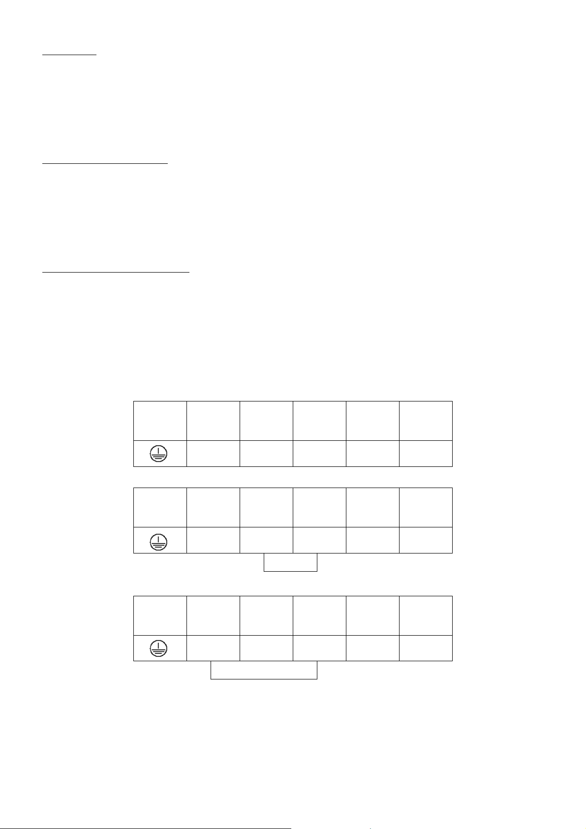
The Xcell 270 unit should be connected as the electrical connection diagrams below:
The Xcell 270 unit should be wired accordingly to obtain the desired speed:
From unit
Mains
From unit
Mains
From unit
Mains
Yellow /
Green
L N
Yellow /
Green
L N
Yellow /
Green
L N
Brown Grey Black Blue
Brown Grey Black Blue
Brown Grey Black Blue
LOW SPEED
MED SPEED
HIGH SPEED
Page 5

The Xcell 270 unit can also be wired through either one of two three speed selector switches as detailed
below:
Page 6

ARRANGEMENT OF THE LIGHT EMITTING DIODES (LED)
7. Red LED - Motor 1 or 2 failure, unit will shut down
6. Green LED - Extract motor 2 running.
Green LED flashing – Exhaust air filter warning
5. Green LED - Intake motor 1 running.
Green LED flashing – Incoming air filter warning
4. Blue LED - Defrost cycle active
3. Yellow LED - Exhaust air temperature >+24
2. Orange LED - Outside air temperature >+24
1. Red LED - Frost protection active, unit will shut down
LED 1. Protective device against the freezing of heating or plumbing.
RED LED illuminates when the exhaust temperature sensor falls below 8°C and switches
the unit off automatically. The unit starts again fully automatically when the temp
increases to 9°C. By pass operates based on the outside and exhaust air temperatures. Two
sensors are sited in the unit.
LED 2 & 3. By pass operation - dependent on internal and external air temperatures.
Two sensors are sited in the unit.
Sequence of functions:
i. When the exhaust air/room air temperature exceeds +24°C the yellow LED
illuminates. The exhaust air/room air temperature is compared with the outside
temperature. If the outside temperature is under +24°C, the bypass flap is opened
immediately and colder outside air flows directly into the dwellings. The bypass flap
remains open until the exhaust air/room air temperature falls below +24°C. The Yellow
LED switches off again.
ii. If both exhaust air and outside air temperatures exceed +24°C both LED’s illuminate
(yellow for exhaust air and orange for outside air). In this operating condition the bypass
closes preventing the dwelling from warming up further (reverse acting heat exchanger). If
the outside temperature cools down again under +24°C, the orange LED switches off and
the bypass flap is opened again until the exhaust air/room air temperature falls below
+24°C.
LED 4. Defrost mode LED illuminates BLUE to indicate defrost is active.
Exhaust air temp in the cell falls below +3°C (freezing up danger). There are two possible
factory settings.
Setting 1: Jumper H7 is fitted. Sequence of functions: Defrost cycle active.
Outside/supply air fan switched off by a timer for 3 hours allowing only warm exhaust air
to the heat exchanger. However if the exhaust temperature increases to +8°C the unit
switches on again to heat recovery. Blue LED goes out. (This option is factory installed to
units without bypass).
Setting 2: Jumper H7 is not fitted. (This option is only on units with bypass). Sequence
of functions: In dwellings with room air dependent fire places the equipment is factory
installed in such a way that the external supply air fan does not switch off, but opens the
bypass flap allowing outside air directly into the living spaces. In this function the bypass
remains opened for 3 hours and thus allows only warm exhaust air to the heat exchanger.
Defrost is completed within 3 hours. However if the exhaust air temperature increases
from +3°C to +8°C within 3 hours the bypass flap is closed automatically and the unit
switches on again to heat recovery mode. Blue LED ‘defrost cycle’ goes out.
o
C
o
C
Page 7

IMPORTANT: For option 2 an electrical duct heater is recommended with a 1500W
output.
LED 5. Motor 1 running OK. External/supply air LED illuminates green (constant)
Motor 1 external/supply air runs at zero resistance (i.e. FID), green LED flashes.
LED 6. Motor 2 running OK. Exhaust/waste air LED illuminates green (constant)
Motor 2 exhaust/waste air runs at zero resistance (i.e. FID), green LED flashes.
LED 5. & 6. Filter monitoring function
This is determined by the power input of the pressure controlled DC motors. If the air
resistance (Pa) increases due to dirty filters to a level greater than the programmed
threshold the two green LED’s flash.
LED 7. Fan motor failure due to blocked rotor or fuse failure
LED illuminates red (constant). The unit will shut down after 75 seconds. Only when the
problem is repaired and the power reconnected to the unit, will the Red LED go out.
Airflow rate speed adjustment.
The Xcell unit is supplied with 3 factory set speed settings as below:
• Speed 1 – Night time setting (or when the building is unoccupied) – 110m3/h
• Speed 2 – Normal setting - 175m3/h
• Speed 3 – Boost setting - 275m3/h
Each of these three settings can be adjusted by means of dip-switches mounted on an internal circuit
board (as below) to give performance appropriate for room size.
Access to this circuit board is through the removable mounting plate situated on the right hand side of the
unit. Ensure that the electrical supply is disconnected to the unit before attempting to access the
circuit board or adjust dip-switch position.
Intake and extract settings can be set independently of each other.
Circuit Board diagram.
Page 8

Dip-switch arrangement
Motor 1 Motor 2
m3/h m3/h
OFF = 0 / ON = 1 Intake OFF = 0 / ON = 1 Extract
1 2 3 4 Outside Air 1 2 3 4 Exhaust Air
0 0 0 0 STOP 0 0 0 0 STOP
1 0 1 0 75 1 0 1 0 75 Speed 1
1 0 0 0 90 1 0 0 0 90 Speed 2
1 1 0 0 110 Factory setting 1 1 0 0 110 Speed 3
0 1 1 0 140 0 1 1 0 140 Speed 4
0 1 0 0 150 0 1 0 0 150 Speed 5
1 1 1 0 160 1 1 1 0 160 Speed 6
1 0 0 1 175 Factory setting 1 0 0 1 175 Speed 7
0 1 0 1 200 0 1 0 1 200 Speed 8
0 0 1 0 225 0 0 1 0 225 Speed 9
1 1 0 1 235 1 1 0 1 235 Speed 10
0 0 0 1 250 0 0 0 1 250 Speed 11
0 0 1 1 275 Factory setting 0 0 1 1 275 Speed 12
1 0 1 1 285 1 0 1 1 285 Speed 13
0 1 1 1 290 0 1 1 1 290 Speed 14
TEST TEST
Speed 1
Speed 2
Speed 3
Maintenance
ALWAYS DISCONNECT FROM THE ELECTRICITY SUPPLY BEFORE OPENING THE DOOR.
Maintenance of the Xcell 270 unit:
• Filter replacement - l x each year
• Heat exchanger cleaning - l x each 6 years
• Motor / impeller cleaning - subject to level of pollution of motors
The home owner may clean and /or replace the Xcell 270 filter without professional assistance. The heat
exchange unit may also be cleaned by the home owner. Cleaning of the motors must only be carried out
by a qualified service engineer.
Filters
The filters consist of G4 grade filter cloth positioned over a metal frame. The used filter can be removed
from the metal frame for cleaning (Filter can be washed with water)
Filter Removal and Repositioning
• Isolate the Xcell 270 unit from the electricity supply
• Open the inspection door by pressing down the two safety catches at the top and bottom of the door
with a screwdriver.
• Open the inspection door fully
• Withdraw the filters from the unit by sliding them out towards you. SEE FILTER SAFETY NOTICE
BELOW!
• Refit new or cleaned filters into same positions in the unit.
• Close the inspection door.
• Lock the inspection door in position by repositioning the two safety catches at the top and bottom of
the door in the locks.
• Reconnect the unit to the electricity supply.
• The Xcell 270 unit is now ready for normal service.
Page 9

Changing air filters - health and safety notice: Used air filters contain quantities of collected dust,
which unless precautions are taken, may expose maintenance personnel to a possible hazard.
Maintenance personnel should therefore wear protective equipment appropriate to the risk. Disposal of
used filters should take into account current waste legislation.
Cleaning Heat Exchanger Unit
Dependant on circumstances, the heat exchanger unit requires cleaning once every six years as a
minimum and once every year as a maximum.
• Isolate the unit from the electricity supply.
• Open the inspection door by pressing down the two safety catches at the top and bottom of the door
with a screwdriver.
• Open the inspection door fully.
• Carefully withdraw the heat exchanger horizontally from its seating-slides in the unit. Make sure not
to damage the seating-slides.
• Clean the heat exchanger by soaking the unit for a minimum of two hours in warm water with
washing up liquid.
• Rinse the unit with water and wait until all water has dripped out of the cleaned unit. Any residual
moisture will evaporate during use.
• Now insert the cleaned heat exchanger unit, sliding it horizontally into its seating-slides.
• Close the inspection door.
• Lock the inspection door in position by repositioning the two safety catches at the top and bottom of
the door in the locks.
• Reconnect the unit to the electricity supply.
• The Xcell 270 unit is now ready for normal service.
Cleaning of Motors
If, when removing the heat exchanger unit, the impeller blades of the ventilators appear to be dirty, then
the impeller blades can be carefully cleaned by dusting with a brush. Removal of the motors must be
done by a qualified service engineer.
Component Description
Outside Casing - Epoxy powder coated sheet metal – Colour RAL 7035
Duct Connection Spigots - Polypropylene 5013 or alternative RAL colour
Internal duct / compartment construction - High density Polystyrene – fully recyclable, non
hygroscopic
Heat recovery cell - Contraflow type. Manufactured from Polystyrol. Fully
recyclable
Filter - Type G4 as standard
Motor - Energy efficient DC motors with constant volume control.
- Metal door powder coated sheet metal – Colour RAL 6029
Maintains same RPM despite resistance, thus optimising
performance.
Page 10

Fault finding
FAULT CHECK POSSIBLE CAUSE
- Intake or Extract fan failure - Supply available - PCB defective.
- Motor connections not connected
- Supply not available. - Power failure.
- Fuse failure
- Air supply fan does - No air from the air - Motor/Electronics defective.
not work entry grilles - Impeller jammed
- Blocked external air inlet
- Incoming airflow restricted - Little air coming from - Filters blocked
supply grilles - Grilles blocked/dirty
- Cell blocked/dirty
- Exhaust airflow restricted - Little air at extract grilles - Filters blocked
- Grilles blocked/dirty
- Cell blocked/dirty
- No condensate drainage - Waterdrops at bottom of - No water in the waste trap.
unit - Condensate drain blocked
- Airlock in pipe
- Unit noisy - Motor noise - Increased resistance through
dirty cell
- Blockage in duct
- Grilles insufficiently opened
- Fan impeller rubbing against
housing
Page 11

Do’s and don’ts
• Do read all the instruction leaflet before commencing installation.
• Do install each fan with a double pole isolating switch.
• Do make sure the mains supply is switched off before attempting to make electrical
connections or carry out any maintenance or cleaning
Guarantee
Customers outside UK – see international below.
• UK: The fan is guaranteed against defects for 5 years from the date of purchase.
• Please keep your purchase receipt.
• If you have any problems, contact Xpelair’s Head Office at the address shown below.
Technical advice and service
Customers outside UK – see international below.
UK: Xpelair have a comprehensive range of services including:
• Free technical advice help-desk from Engineers on all aspects of ventilation
• Free design service, quotations and site surveys
• Service and maintenance contracts to suit all requirements.
Please ask for details:
• By telephone on Techline:+44 (0) 8709 000430
• By fax on Techfax:+44 (0) 8709 000530
• At the address below
International
• Guarantee: Contact your local distributor or Xpelair direct for details.
• Technical Advice and Service: Contact your local Xpelair distributor
Applied Energy Products Ltd
Morley Way
Peterborough
PE2 9JJ
t 01733 456789
f 01733 310606
www.applied-energy.com
Xpelair is a registered trademark of Applied Energy Products Limited.
Applied Energy Products reserve the right to alter product
specifications
or appearance without prior notice. All finishes and diagrams in this
91264AW / 91265AW
 Loading...