

Page 1

INSTALLATION INSTRUCTIONS
FOR COMPLETE FAN LIGHT KIT
BriteX LoVolt & BriteX Turbo
GENERAL MOUNTING AND SAFETY NOTES
1. WHEN INSTALLING FANS SWITCH OFF MAINS SUPPLY BEFORE MAKING ELECTRICAL
CONNECTIONS. All wiring must comply with current IEE regulations. If in doubt, consult a qualified electrician.
2. Extraction fans should not be located in rooms containing open flued appliances.
3. Do not install 240V fans in a shower or bathroom application where the fan may be within reach of someone using a
bath or shower, or subjected to water spray (zones 0, 1 and 2). The 12V VentLight is suitable for use in shower
cubicles.
4. Do not install fan directly behind shutter grille.
5. These fans are double insulated and do not require an earth connection.
6. For systems incorporating back draught shutters ensure that the shutter grille is mounted on a vertical wall with the
shutters orientated correctly. Take care to ensure that shutter movement is not restricted.
7. Maximum fan operating temperature 40°C.
8. Xpelair guarantees for 3 years against defects in the materials or manufacture of the Xpelair fan range from the date of
purchase (when installed to manufacturers requirements and used in a normal domestic operation) (2 years for the
BriteX Turbo).
Timer versions
Timer is adjustable between 2 to 20 minutes run time. Fans have been factory set at minimum. Using a small flat bladed
screwdriver adjust dial on circuit board by turning clockwise to reduce run time and anticlockwise to extend run time
(BX100WT and BX100CT models only).
Note: a means for
disconnection in all poles
must be incorporated in the
fixed wiring in accordance
with the wiring rules. We
recommend a ceiling
switch mounted in a
suitable position.
SL = Switched Live.
To suit Timer Models: BX100WT, BX100CT, BX100+WT, BX100+CT
To suit Standard Models: BX100W, BX100C, BX100+W, BX100+C
Note: a means for
disconnection in all poles
must be incorporated in
the fixed wiring in
accordance with the
wiring rules. We
recommend a ceiling
switch mounted in a
suitable position.
Page 2
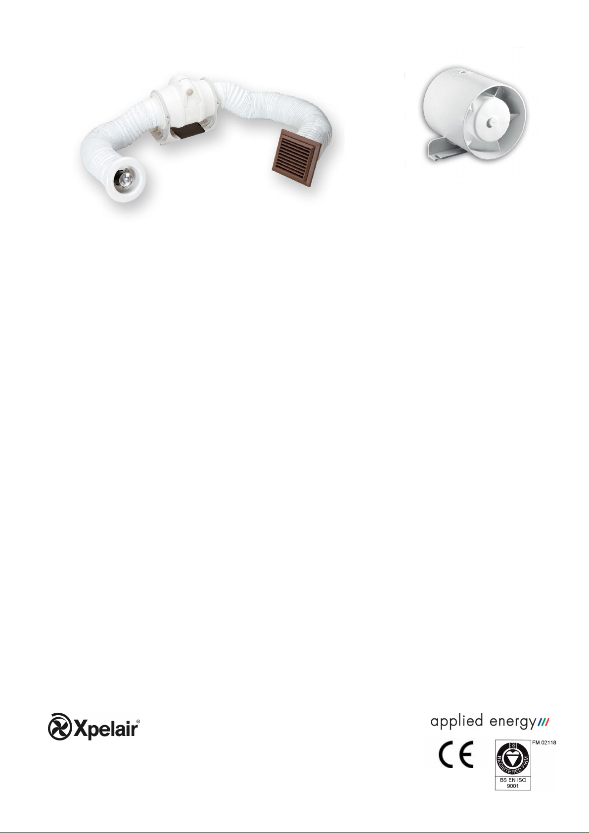
Britex Turbo Shown
Britex LoVolt
Fan Unit
FAN & DUCT INSTALLATION INSTRUCTIONS
BriteX LoVolt
1. Determine position for fan and ducting. Locate and prepare external opening and determine Fan light position. NOTE:
Fan will perform best if ducting is kept as straight as possible (ie. at least 4 duct diameter lengths either side of fan
body).
2. Secure fan to joist, either on top (using a plank if necessary) or on the side – but not under any roof insulation. Secure
it with the fan blades towards the external grille using two screws through the fixing bracket – the arrow on the body
shows the direction of airflow.
3. Remove the cover of the fan by springing out the spring clips.
4. Make electrical connections as per wiring diagrams set out overleaf. Preferably align the cable with one of the upper
spokes in the fan to ensure minimum resistance to airflow.
5. Replace fan cover by snap fitting into place.
6. Pass ducting through walls, soffit and/or ceiling as required, fit ducting to grille using tie wraps, then fix grille in
place.
7. Pull the flexible ducting gently to the discharge end of the fan and cut and fit ducting to fan casing using tie wraps. Slit
duct to clear cable taking care to ensure that duct reinforcing wire does not contact cable. Extend ducting fully and
take care to install ducting with minimal changes in direction.
8. For BriteX Turbo fan installation instructions, please refer to the handbook supplied with the fan.
FAN LIGHT UNIT INSTALLATION INSTRUCTIONS
1. Cut a 102mm diameter hole in the ceiling ensuring that the hole lies between the roof joists.
2. Fix the fixing clips to the Fan Light body using the screws provided and push the fan light into the ceiling hole. The
clips secure the fan light body in position.
3. The power supply to the Fan Light transformer must be wired in parallel with the fan supply to ensure that the
fan extracts when the Fan Light is illuminated in order to remove excess heat.
4. Connect the two white wires from the Fan Light to the 12V 70VA SELV transformer terminals marked 11.5V.
Connect a 1.5mm cable between one set of the transformer L and N terminals marked 230V-240V and the Neutral and
Live (Standard) or Neutral and Switched Live (Timer) connections on the fan.
Reference should be made to the fan instructions.
5. Cut and then connect the ducting to the Fan Light using one of the tie wraps provided in the ceiling fan kit. Slit the end
of the duct to clear the cable, taking care to ensure that the duct reinforcing wire does not damage the cable insulation.
CAUTION: In use, the lamp becomes extremely hot. Ensure that the lamp has cooled before removal or replacement.
Replacement dichroic lamps: Sealed 12Vac, 35W maximum, G5.3 fitting, FMW.
Applied Energy Products Ltd
Morley Way, Peterborough, PE2 9JJ, ENGLAND
Telephone: +44(0) 1733 456789
Fax: +44(0)1733 310606
Sales Hotline: +44(0) 8709 000420
http:\\www.xpelair.co.uk
22739AA
Revision B
 Loading...