

Page 1

GB
NL
AWC
Fan Controller
AWC Ventilatorregelaar
Lüfterregler
Variateur de ventilateur
Regolatore per aspiratori AWC
®
D
F
I
Installation and operating instructions
Installatie- en bedieningsinstructies
Installations- und Bedienungsanleitung
Notice d’installation et d’utilisation
Istruzioni di installazione e funzionamento
Retain for future reference
Bewaar voor gebruik later
Zum zukünftigen Gebrauch aufbewahren
Prière de conserver pour référence ultérieure
Da conservare per futura consultazione
Page 2
Xpelair AWC
Fan Controller
These instructions are for the Installation and Operation of the
AWC Fan Controller only. For Fan Installation and Operating
Instructions refer to literature provided with appropriate fan.
General Information
Description
This appliance is designed to control the
operation of Xpelair NWAN Whispair fan range.
It is designed to minimise the temperature
differential between high and low levels in large
buildings. The unit is supplied with two
temperature sensors and can be used to
operate up to ten NWAN ceiling sweep fans.
The AWC can be operated in either automatic
or manual modes.
IN AUTOMATIC MODE:
• If the control knob is set in the fully anti-
clockwise position, minimum fan speed
occurs when the difference in high and low
level temperatures is 3ºC or less; maximum
speed occurs when the difference is 6ºC or
more.
• If the control knob is set in the fully clockwise
position, minimum fan speed occurs when
the difference in high and low level
temperatures is 10ºC or less; maximum
speed occurs when the difference is 13ºC or
more.
• To reduce the temperature difference at
which the fan speed will vary, turn the control
knob anticlockwise. Increase by turning
clockwise.
IN MANUAL MODE:
• To reduce the fan speed, turn the knob
anticlockwise. To increase the fan speed, turn
it clockwise.
IN AUTOMATIC AND MANUAL MODES:
• The fan comes on automatically at full speed
for the first 10 seconds before reverting to
the speed selected.
• The AWC can be either surface or recess
mounted using the metal wall box supplied.
Installing the Controller
These installation instructions are for the
installation of the controller when used in
combination with Xpelair supplied fans.
The controller must be installed to
fixed wiring. Ensure the Main
Electrical Supply matches the rating
shown on the controller casing.
THIS APPLIANCE MUST BE EARTHED!
All installation must be supervised by a
qualified electrician.
Installation and wiring must conform to
current IEE wiring regulations (UK), or local
appropriate regulations (other countries).
If you have any queries either before, during
or after the installation of the controller,
please do not hesitate to contact the UK
Xpelair hotline (number on back page).
Customers outside UK: contact your local
Xpelair distributor.
What the installer will need
• A double pole isolating switch with a
minimum contact gap of 3mm (Wall or Ceiling
mounted).
• Suitably rated 4-core cable to connect the
controller to the fan/s.
• Suitably rated 3-core cable to connect the
controller to the Main Electrical Supply.
If using flexible cable, suitable
glands incorporating cable clamps
must be fitted to the knockouts in
the Controller Box.
Refer to Fig 1.
Location of the Controller
• Not where ambient temperatures are likely to
exceed 50
• If installed in a kitchen the Controller must
not be mounted immediately above a cooker
or eye level grill.
• When intended for use in possible chemical
corrosive atmospheres, consult our Technical
Service Department (outside the UK contact
your local Xpelair distributor)
• If installed in a shower room or bathroom the
controller and isolating switch must be
situated so that they cannot be touched by
persons making use of the bath or shower.
Location of the Sensors
• Not where temperatures exceed 35
• Pointing away from walls or other
obstructions, to ensure adequate ventilation.
• High level sensor, above fan mounting height.
• Low level sensor, within 1m of the controller.
• When intended for use in possible chemical
corrosive atmospheres, consult our Technical
Service Department (Outside the UK contact
your local Xpelair distributor)
0
0
c
Page 3
Working with the Fan
If wiring to an existing installation
isolate mains supply and remove
applicable fuses prior to any
electrical procedure.
If the fan is already installed.
1. Ensure the power supply is isolated.
2. Disconnect the mains connections from the
fan’s terminal socket or from the terminal
block.
3. Remove the existing wiring and make it safe.
If the fan is not already installed.
1. Check that the fan electrical rating matches
the power supply.
2. Mount the fans in accordance with the
instructions supplied.
3. Route the four core cable from the controller
position to each fan.
4. Route the three core cable from controller
position to the isolator position.
Mounting the Controller
Remove the Cover and Mounting Frame.
1. Detach the Fascia from the Mounting Frame
by removing the screw covers and two
screws (Refer to Fig. 2a & b).
2. Detach mounting Frame from the Wall Box by
removing the two screws (Refer to Fig. 2c).
3. Lift the Wall Box away from the Plastic
Surround.
4. Check that the electrical rating shown inside
the controller matches the power supply.
5. Disconnect the earth wire from the Wall Box.
6. Make cable entry holes in the plastic and
metal boxes by removing suitable knockouts
(Refer to Fig. 1).
If recess mounting
1. Make a hole in the wall big enough to take
the Wall Box.
2. Insert suitable glands into the knockouts.
3. Feed both cables through these glands.
4. Fix the Wall Box to the wall. Ensure that the
flange of the mounting frame fits flush to the
finished surface of the wall (Refer diagram F3.
5. Re-connect the earth lead to the Wall Box.
Mounting the Sensors
Using the two clips supplied, mount the
temperature sensors horizontally, without
touching the walls or ceiling.
• Mount the sensor with the 10m cable in the
high level position.
• Mount the sensor with the 1m cable in the
low level position suitably protected.
• Install the cables in closed conduits, leaving
the other ends ready to wire into the
controller.
Wire the Controller electrical connections
1. Mount the Isolation Switch in accordance
with the manufacturers instructions.
2. Wire the Controller to the Isolation Switch and
to the Fan as shown in the appropriate
diagram F1.
3. Connect the sensor cables to the high and
low sensor terminals.
4. Connect any remaining fans in parallel.
5. Refit Mounting Frame to Metal Wall Box.
6. Refit the Fascia to the Mounting Frame.
7. Refit the Screw Covers.
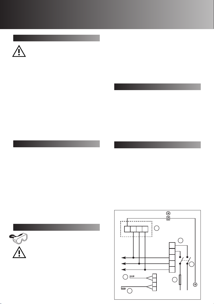
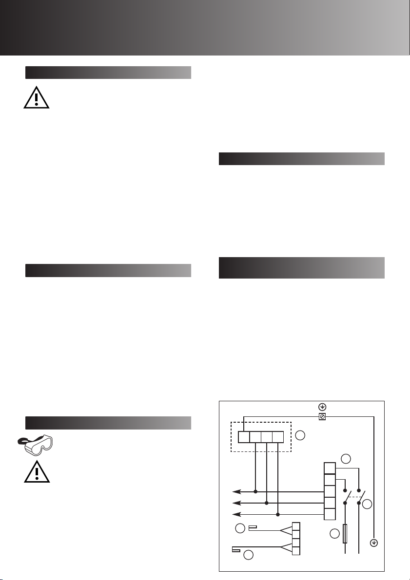
F1
Mounting the Wall Box
Eye protection must be worn during
all drilling and chiselling operations.
Check there are no buried Pipes or
Cables in the wall or obstructions on
the outside e.g. Electricity, Gas,
Water.
If surface mounting
1. Insert suitable glands into the knockouts.
2. Feed both cables through the glands.
3. Fix the Wall Box and Plastic Surround to the
wall, using the mounting holes provided.
4. Re-connect the earth lead to the Wall Box.
LF LR
EN
3
4
FUSE 6.3 AMP F RATED
1
LOW
HIGH
N
L
NF
LF
LR
2
5
6
LN
Page 4
Connect to Power Supply
1. Ensure power supply is isolated and fuses are
removed.
2. Route the Cable from the Isolating Switch to
the point of connection to the power supply.
3. Make all connections within the isolating
Switch in accordance with the manufacturers
instructions.
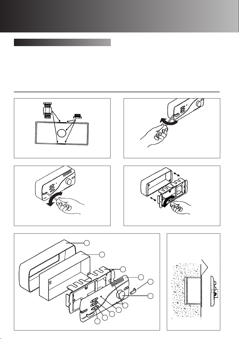
Fig 1. Cable gland positions Fig 2a. Removing screw covers
4. Following all IEE and local regulations make
connection at point of power supply.
5. Make a final check to ensure all earth points
are connected and all covers have been
correctly replaced on the fan, controller and
isolating switch.
6. Replace all fuses, and switch on the power
supply.
Fig 2b. Removing fascia Fig 2c. Removing mounting frame
F2
17
16
15
14
13
12
11
10
7
8
9
F3
Ensure mounting frame
flange fits flush to the wall
Page 5
KEY TO DIAGRAMS
F1
1) Fan terminal block
2) Controller terminal block
3) Low sensor
4) High sensor
5) Double pole isolator
6) Fuse (6.3 amp F rated)
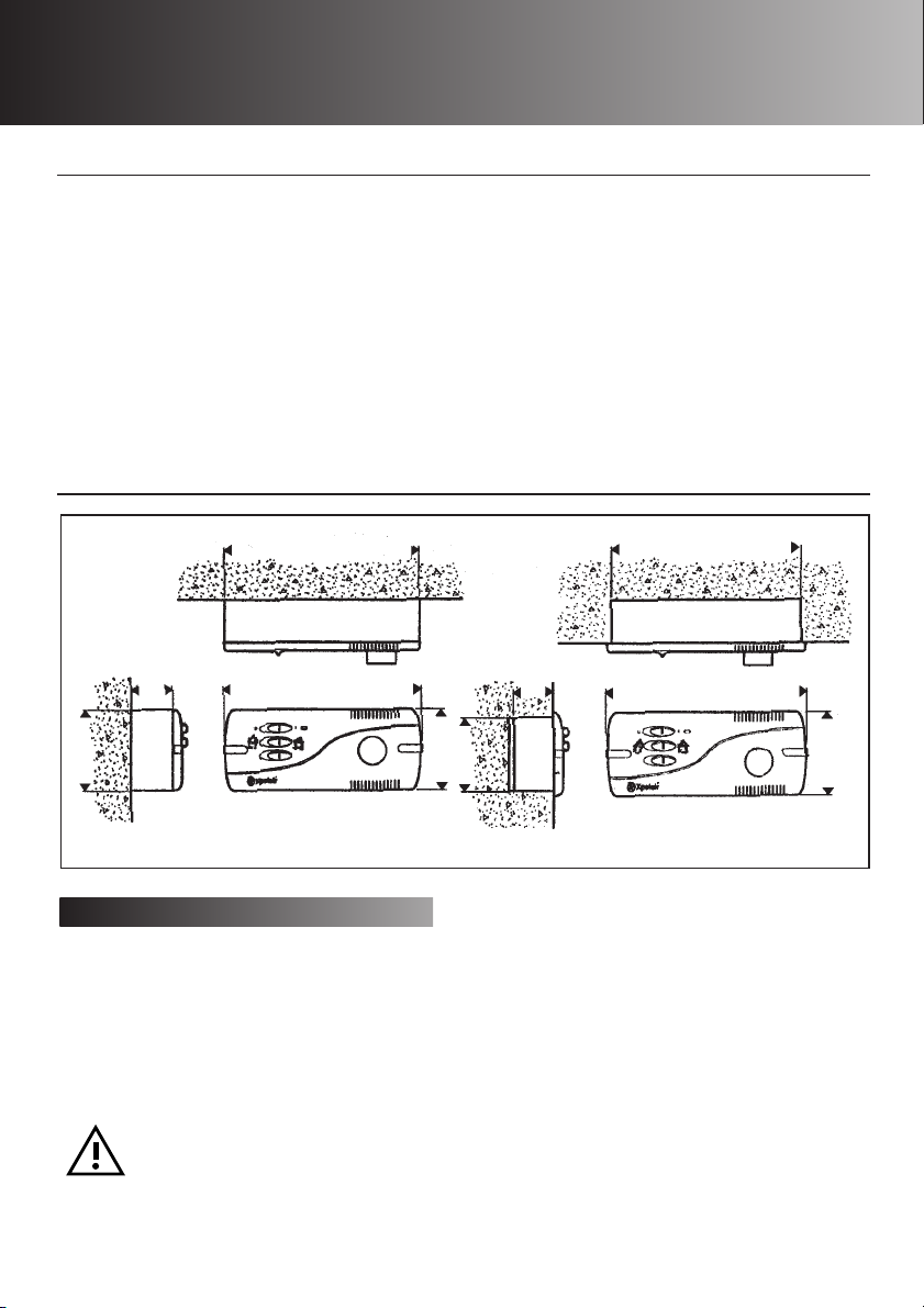
F4
45mm
86mm
F2
7) ON/OFF switch
8) Forward or reverse running
9) Automatic or manual mode
10) Fan running indicator light
11) Ventilation slots
12) Speed/temperature setting
13) Screw cover
14) Fascia
15) Mounting frame
16) Metal wall box
17) Plastic surround
206mm
210mm
86mm
81mm
41mm
182mm
210mm
86mm
Looking after the controller
CLEANING
1. Before cleaning isolate the controller
completely from the power supply.
2. Wipe the cover carefully with a damp cloth.
3. Dry thoroughly.
4. Ensure ventilation slots are free from
obstructions at all times.
• Never immerse the controller in
water or other liquids.
• Never use solvents to clean the
controller.
• Apart from cleaning, no other
maintenance is required.
Page 6
Xpelair AWC
Ventilatorregelaar
Deze instructies zijn alleen bedoeld voor de installatie en bediening van de
AWC Ventilatorregelaar. Voor de installatie- en bedieninginstructies van de
ventilator, zie de documentatie die bij de van toepassing zijnde ventilator is
geleverd.
Algemene informatie
Omschrijving
Dit apparaat is ontworpen om de bediening van Xpelair
NWAN Whispair ventilatoren te regelen.
Het is ontworpen om het temperatuurverschil tussen
hoge en lage niveaus in grote gebouwen te
minimaliseren. De unit is uitgerust met twee
temperatuursensors en kan worden gebruikt voor de
bediening van maximaal tien NWAN
plafondventilatoren.
De AWC kan ofwel in automatische of in handmatige
stand worden gebruikt.
IN AUTOMATISCHE STAND:
• Wanneer de regelknop volledig linksom is ingesteld,
is de ventilatorsnelheid minimaal wanneer het
temperatuurverschil tussen hoge en lage niveaus 3º
C of minder is; wanneer het verschil 6º C of meer is,
dan is de ventilatorsnelheid maximaal.
• Wanneer de regelknop volledig rechtsom is
ingesteld, is de ventilatorsnelheid minimaal wanneer
het temperatuurverschil tussen hoge en lage
niveaus 10º C of minder is; wanneer het verschil 13º
C of meer is, dan is de ventilatorsnelheid maximaal.
• Om het temperatuurverschil waarbij de
ventilatorsnelheid varieert te verlagen, dient de
regelknop linksom te worden gedraaid. Om het
temperatuurverschil te verhogen dient de regelknop
rechtsom te worden gedraaid.
IN HANDMATIGE STAND:
• Om de ventilatorsnelheid te verlagen, dient de
regelknop linksom te worden gedraaid. Om de
ventilatorsnelheid te verhogen, dient de regelknop
rechtsom te worden gedraaid.
IN AUTOMATISCHE EN HANDMATIGE STAND:
• In automatische stand draait de ventilator de eerste
10 seconden op volle snelheid voordat hij naar de
gekozen snelheid terugvalt.
• De AWC kan aan de oppervlakte of verzonken
worden gemonteerd met gebruik van de
meegeleverde metalen muurdoos.
Installeren van de regelaar
Deze installatie-instructies zijn bedoeld voor de
installatie van de regelaar wanneer deze wordt
gebruikt in combinatie met ventilatoren die door
Xpelair zijn geleverd.
De regelaar moet op vaste bedrading
worden aangesloten. Zorg dat de
elektrische gegevens die op de behuizing
van de regelaar staan vermeld
overeenkomen met de netvoeding.
DIT APPARAAT MOET GEAARD ZIJN!
Alle installatiewerkzaamheden moeten onder
toezicht van een gekwalificeerde elektricien
worden uitgevoerd.
Montage en bedrading moeten voldoen aan de
huidige IEE-voorschriften (VK), of plaatselijke
toepasselijke voorschriften (andere landen).
Wanneer u voor, tijdens of na het installeren van
de regelaar vragen heeft, kunt u contact
opnemen met de technische hotline van Xpelair
(nummer op achterblad).
Voor overzeese markten kunt u contact opnemen
met uw plaatselijke Xpelair distributeur.
Wat de installateur nodig heeft
• Een dubbelpolige isolatieschakelaar met een
minimum contactafstand van 3mm (muur- of
plafondbevestiging).
• Geschikte 4-aderige kabel om de regelaar op de
ventilator(en) aan te sluiten.
• Geschikte 3-aderige kabel om de regelaar op het
lichtnet aan te sluiten.
Wanneer een flexibele kabel wordt
gebruikt, dienen geschikte wartels met
kabelklemmen op de uitduwstukken in
de regeldoos te worden gemonteerd.
Zie figuur 1.
Plaats van de regelaar
• Niet daar waar de omgevingstemperatuur hoger
dan 50°C kan worden.
• Wanneer de regelaar in een keuken wordt
geïnstalleerd, mag hij niet direct boven een fornuis
of gril op ooghoogte worden gemonteerd.
• Wanneer de ventilator bedoeld is voor gebruik in
een mogelijk chemisch corrosieve omgeving,
moet u contact opnemen met onze technische
service-afdeling. (Voor overzeese markten kunt u
contact opnemen met uw plaatselijke Xpelair
distributeur).
• Wanneer hij in een doucheruimte of badkamer
wordt geïnstalleerd, moeten de regelaar en de
isolatieschakelaar zo worden geplaatst dat
personen die een douche of bad nemen de
ventilator niet kunnen aanraken.
Plaats van de sensors
• Niet daar waar de omgevingstemperatuur hoger
dan 35°C kan worden.
• Niet gericht op muren of andere obstructies, om
adequate ventilatie te verzekeren.
• Sensor op hoog niveau, boven hoogte van
ventilatorbevestiging.
• Sensor op laag niveau, binnen 1m van de
regellaar.
• Wanneer de ventilator bedoeld is voor gebruik in
een mogelijk chemisch corrosieve omgeving,
moet u contact opnemen met onze technische
service-afdeling. (Voor overzeese markten kunt u
contact opnemen met uw plaatselijke Xpelair
distributeur).
Page 7
Werken met de ventilator
Als u de bedrading op een bestaande
installatie aansluit, sluit dan, voordat
elektrische werkzaamheden worden
uitgevoerd, de netvoeding af en
verwijder de van toepassing zijnde
zekeringen.
Wanneer de ventilator reeds geïnstalleerd is
1. Zorg dat de netvoeding afgesloten is.
2. Maak de netvoedingaansluitingen los van de
klembus van de ventilator of van het contactblok.
3. Verwijder de bestaande bedrading en beveilig ze.
Wanneer de ventilator nog niet geïnstalleerd is
1 Controleer of de elektrische gegevens van de
ventilator overeenkomen met de netvoeding.
2. Monteer de ventilators in overeenstemming met
de meegeleverde instructies.
3. Leid de 4-aderige kabel van de plaats van de
regelaar naar elke ventilator.
4. Leid de 3-aderige kabel van de plaats van de
regelaar naar de plaats van de isolator.
Monteren van de regelaar
Verwijder de kap en het montageraam.
1. Maak de voorplaat los van het montageraam
door de schroefdoppen en twee schroeven te
verwijderen (Zie fig. 2a & b).
2. Maak het montageraam los van de muurdoos
door de twee schroeven te verwijderen (Zie fig.
2c).
3. Haal de muurdoos weg van de plastic
montageplaat.
4. Controleer of de elektrische gegevens van de
ventilator overeenkomen met de netvoeding.
5. Maak de aardingskabel los van de muurdoos.
6. Maak gaten voor de kabels in de plastic en
metalen dozen door van toepassing zijnde
uitduwstukken te verwijderen (Zie fig. 1).
Monteren van de muurdoos
Bij alle boor- en breekwerkzaamheden
moet oogbescherming worden
gedragen.
Controleer of er geen verborgen
leidingen of kabels van elektriciteit, gas,
of water door de muur lopen en of er
geen obstructies aan de buitenkant van
de muur zitten.
Montage aan de oppervlakte
1. Plaats geschikte wartels in de uitduwstukken.
2. Voer beide kabels door deze wartels.
3. Bevestig de muurdoos en plastic montageplaat
aan de muur en gebruik hierbij de voorziene
bevestigingsgaten.
4. Sluit de aardingskabel weer op de muurdoos aan.
Montage in de muur
1. Maak een gat in de muur dat groot genoeg is voor
de muurdoos.
2. Plaats geschikte wartels in de uitduwstukken.
3. Voer beide kabels door deze wartels.
4. Bevestig de muurdoos in de muur. Zorg dat de flens
van het montageraam gelijk ligt met de afgewerkte
oppervlakte van de muur. (Zie schema F3).
5. Sluit de aardingskabel weer op de muurdoos aan.
Monteren van de sensors
Monteer, met gebruik van de twee meegeleverde
klemmen, de temperatuursensors horizontaal zonder
de muren of het plafond te raken.
• Monteer de sensor met de 10m kabel in de
positie op hoog niveau.
• Monteer de sensor met de 1m kabel, goed
beschermd in de positie op laag niveau.
• Installeer de kabels in gesloten elektriciteitsbuizen,
en zorg dat de tegenoverliggende einden klaar
zijn om op de regelaar te worden aangesloten.
Sluit de elektrische verbindingen van de
regelaar aan
1. Monteer de isolatieschakelaar in overeenstemming
met de instructies van de fabrikant.
2. Sluit de bedrading van de regelaar op de
isolatieschakelaar en de ventilator aan, zoals in het
van toepassing zijnde schema F1 wordt vertoond.
3. Sluit de sensorkabels op de hoge en lage
sensoraansluitingen aan.
4. Sluit de overige ventilatoren parallel aan.
5. Monteer het montageraam weer aan de metalen
muurdoos.
6. Monteer het voorpaneel weer aan het
montageraam.
7. Breng de schroefdoppen weer aan.
F1
LF LR
EN
3
4
ZEKERING, SNEL 6.3 AMP
1
LAAG
HOOG
N
L
NF
LF
LR
2
5
6
LN
Page 8

Aansluiting op lichtnet
1. Sluit de netvoeding af en verwijder de
zekeringen.
2. Verbind de kabel vanuit de
scheidingsschakelaar met de elektrische
bedrading.
3. Maak alle verbindingen in de isolatieschakelaar
in overeenstemming met de instructies van de
fabrikant.
Fig 1. Plaatsen van kabelwartel Fig 2a. Verwijderen van schroefdoppen
4. Maak een verbinding met de netvoeding en volg
hierbij alle IEE- en plaatselijke voorschriften.
5. Voer een laatste controle uit om te verzekeren
dat alle aardpunten zijn aangesloten en dat alle
kappen goed op de ventilator, regelaar en
isolatieschakelaar zijn aangebracht.
6. Zet alle zekeringen terug en zet de stroom aan.
Fig 2b. Verwijderen van voorplaat Fig 2c. Verwijderen van montageraam
F2
17
16
15
14
13
12
11
10
7
8
9
F3
Zorg dat de flens van het
montageraam in lijn met
de muur is.
Page 9

LEGENDA
F1
1) Contactblok van ventilator
2) Contactblok van regelaar
3) Lage sensor
4) Hoge sensor
5) Dubbelpolige isolator
6) Zekering, snel (6.3 amp)
F4
45mm
86mm
F2
7) AAN-/UITSCHAKELAAR
8) Vooruit of achteruit draaien
9) Automatische of handmatige stand
10) Indicatielampje voor ventilator draait
11) Ventilatiesleuven
12) Instelling van snelheid/ temperatuur
13) Schroefdop
14) Voorpaneel
15) Montageraam
16) Metalen muurdoos
17) Plastic montageplaat
206mm
210mm
86mm
41mm
81mm
182mm
210mm
86mm
Onderhoud van de regelaar
REINIGEN
1. Sluit vóór het reinigen de regelaar volledig van de
netvoeding af.
2. Veeg de kap voorzichtig met een vochtige doek
af.
3. Droog hem zorgvuldig.
4. Zorg dat de ventilatiesleuven te allen tijde vrij van
obstructies zijn.
• Dompel de regelaar nooit onder
in water of in andere vloeistoffen.
• Gebruik nooit oplosmiddelen om
de regelaar te reinigen.
• Behalve het reinigen is er geen
verder onderhoud nodig.
Page 10

Xpelair AWC
Lüfterregler
Die vorliegende Betriebsanleitung dient nur zur Installation und
Bedienung des AWC Lüfterreglers. Zur Installation und Bedienung
des Lüfters siehe zum Lüfter zugehörige Dokumentation.
Allgemeine Informationen
Beschreibung
Dieses Gerät ist zur Regelung des Betriebs des Xpelair
NWAN Whispair Lüftersortiments ausgelegt.
Es dient dazu, die Temperaturdifferenz zwischen der
hohen und niedrigen Temperaturstufe in großen
Gebäuden zu minimieren. Das Gerät wird mit zwei
Temperatursensoren geliefert und kann zur Regelung
von bis zu zehn NWAN Deckenventilatoren verwendet
werden.
Der AWC kann in der automatischen oder manuellen
Betriebsart betrieben werden.
AUTOMATISCHE BETRIEBSART:
• Wird der Drehknopf vollständig gegen den Uhrzeig-
ersinn gedreht, so wird die minimale Lüfterdrehzahl
eingestellt, wenn der Unterschied zwischen der hohen
und niedrigen Temperaturstufe 3ºC oder weniger
beträgt; die maximale Drehzahl wird eingestellt, wenn
der Unterschied 6ºC oder darüber beträgt.
• Wird der Drehknopf vollständig im Uhrzeigersinn
gedreht, so wird die minimale Lüfterdrehzahl eingestellt, wenn der Unterschied zwischen der hohen
und niedrigen Temperaturstufe 10ºC oder weniger
beträgt; die maximale Drehzahl wird eingestellt, wenn
der Unterschied 13ºC oder darüber beträgt.
• Zur Senkung des Temperaturunterschieds, bei dem
die Lüfterdrehzahl variiert, wird der Drehknopf gegen
den Uhrzeigersinn gedreht. Um diesen zu erhöhen,
wird im Uhrzeigersinn gedreht.
MANUELLE BETRIEBSART:
• Zum Senken der Lüfterdrehzahl wird der Knopf
gegen den Uhrzeigersinn gedreht. Um diese zu
erhöhen, wird im Uhrzeigersinn gedreht.
AUTOMATISCHE UND MANUELLE BETRIEBSART:
• Der Lüfter schaltet sich automatisch ein und läuft die
ersten zehn Sekunden lang mit maximaler Drehzahl,
bevor er mit der eingestellten Drehzahl weiterläuft.
• Der AWC kann entweder auf Putz oder unter
Verwendung der beiliegenden Metall-Wanddose
unter Putz montiert werden
Installation des Reglers
Die folgende Montageanleitung gilt zur Installation des
Reglers, wenn dieser in Kombination mit von Xpelair
gelieferten Lüftern verwendet wird.
Die Verkabelung des Reglers muss fest
verlegt werden. Überzeugen Sie sich
davon, dass die Netzspannungsversorgung den auf dem Reglergehäuse
angegebenen Werten entspricht.
DIESES GERÄT MUSS GEERDET WERDEN!
Sämtliche Installationsarbeiten müssen von einem
qualifizierten Elektriker überwacht werden.
Installation und Anschlüsse müssen gemäß den
geltenden IEE-Vorschriften (GB) bzw. den im
jeweiligen Land geltenden Vorschriften (andere
Länder) vorgenommen werden.
Sollten Sie vor, während oder nach der Installation
des Reglers Fragen haben, so wenden Sie sich
bitte an den technischen Kundendienst von UK
Xpelair (die entsprechende Telefonnummer finden
Sie auf der Rückseite). Kunden außerhalb
Großbritanniens: Wenden Sie sich bitte an Ihre
zuständige Xpelair Regionalvertretung.
Was der Installateur benötigt
• Einen zweipoligen Trennschalter mit einem
Kontaktabstand von mindestens 3 mm
(Wand- oder Deckenmontage).
• Vieradriges Kabel geeigneter Bemessung
zum Anschluss des Reglers an den/die Lüfter.
• Dreiadriges Kabel geeigneter Bemessung
zum Anschluss des Reglers an die
elektrische Spannungsversorgung.
Wird biegsames Kabel verwendet, so
sind an den Ausdrückern der Reglerdose
geeignete Stopfbüchsen mit integrierten
Kabelklemmen anzubringen.
Siehe Abb. 1.
Wo sollte der Regler installiert werden?
• Nicht an Stellen, an denen Umgebungstemperaturen
von 50°C überschritten werden können.
• Bei der Installation in der Küche darf der Regler nicht
direkt über einem Herd oder einem auf Augenhöhe
befindlichen Grill angebracht werden.
• Vor der Installation des Reglers in Umgebungen mit
möglicher korrosiver Chemikalienbelastung lassen
Sie sich bitte von unserem technischen Kundendienst
beraten. (Außerhalb Großbritanniens wenden Sie sich
bitte an Ihre zuständige Xpelair Regionalvertretung.)
• Bei der Installation in einer Dusche oder im
Badezimmer müssen Regler und Trennschalter so
angebracht werden, dass eine Berührung während
des Duschens oder Badens ausgeschlossen ist.
Wo sollten die Sensoren installiert werden?
• Nicht an Stellen, an denen Temperaturen von 35°C
überschritten werden können.
• Die Sensoren müssen von Wänden oder anderen
Objekten wegweisen, damit eine adäquate
Ventilation gewährleistet ist.
• Der Sensor für die hohe Temperaturstufe muss
höher als der Lüfter angebracht werden.
• Der Sensor für die niedrige Temperaturstufe muss
innerhalb von einem Meter des Reglers angebracht
werden.
• Vor der Installation der Sensoren in Umgebungen
mit möglicher korrosiver Chemikalienbelastung
lassen Sie sich bitte von unserem technischen
Kundendienst beraten. (Außerhalb Großbritanniens
wenden Sie sich bitte an Ihre zuständige Xpelair
Regionalvertretung.)
Page 11

Arbeiten am Lüfter
Wird der Regler an einer vorhandenen
Installation angeschlossen, so sind vor dem
Ausführen der Arbeiten an der Elektrik die
Spannungsversorgung zu trennen und die
entsprechenden Sicherungen zu entfernen.
Bei bereits installiertem Lüfter:
1. Davon überzeugen, dass die Spannungsversorgung
getrennt ist.
2. Die Netzanschlüsse von der Anschlussklemme des
Lüfters bzw. vom Anschlussklemmenblock trennen.
3. Die vorhandene Verdrahtung entfernen und Gerät
sichern.
Bei noch nicht installiertem Lüfter:
1. Prüfen, dass die auf dem Lüfter angegebenen
elektrischen Betriebswerte mit der Netzversorgung
übereinstimmen.
2. Die Lüfter in Übereinstimmung mit der beiliegenden
Anleitung montieren.
3. Das vieradrige Kabel vom Regler zu den einzelnen
Lüftern führen.
4. Das dreiadrige Kabel vom Regler zum Trennschalter
führen.
Installation des Reglers
Abdeckung und Befestigungsrahmen entfernen.
1. Die Stirnplatte vom Befestigungsrahmen trennen.
Hierzu werden die beiden Schraubenkappen
entfernt und die zwei Schrauben herausgedreht
(siehe Abb. 2a & b).
2. Den Befestigungsrahmen von der Wanddose
trennen, indem die beiden Schrauben
herausgedreht werden (siehe Abb. 2c).
3. Die Wanddose aus der Kunststoff-Einfassung
herausheben.
4. Prüfen, dass die im Regler angegebenen
elektrischen Betriebswerte mit der Netzversorgung
übereinstimmen.
5. Das Massekabel von der Wanddose trennen.
6. Kabeleinlasslöcher in den Kunststoff- und
Metalldosen herstellen, indem die entsprechenden
Ausdrücker entfernt werden (siehe Abb. 1).
Montage der Wanddose
Bei Bohr- und Meißelarbeiten ist stets
eine Schutzbrille zu tragen.
Kontrollieren, dass hinter der geplanten
Dosenposition in der Wand oder außen an
der Wand keine Rohre oder Kabel für
Strom, Gas oder Wasser oder sonstige
Hindernisse verlaufen.
Bei Aufputzmontage
1. Geeignete Stopfbüchsen in die Ausdrücker einfügen.
2. Beide Kabel durch die Stopfbüchsen führen.
3. Die Wanddose und die Kunststoff-Einfassung unter
Verwendung der entsprechenden Befestigungslöcher
an der Wand befestigen.
4. Das Massekabel wieder an der Wanddose
anschließen.
Bei Unterputzmontage
1. Ein Loch in die Wand schneiden, das zur Aufnahme
der Wanddose groß genug ist.
2. Geeignete Stopfbüchsen in die Ausdrücker einfügen.
3. Beide Kabel durch die Stopfbüchsen führen.
4. Die Wanddose an der Wand sichern. Sicherstellen,
dass der Flansch des Befestigungsrahmens mit der
Wandfläche bündig ist (siehe Schema F3).
5. Das Massekabel wieder an der Wanddose
anschließen.
Installation der Sensoren
Mit den beiden beiliegenden Klemmen die
Temperatursensoren horizontal anbringen, ohne dass
diese die Wand oder die Decke berühren.
• Den Sensor mit dem 10 m langen Kabel in der
Stellung für die hohe Temperaturstufe anbringen.
• Den Sensor mit dem ein Meter langen Kabel in der
Stellung für die niedrige Temperaturstufe
entsprechend geschützt anbringen.
• Die Kabel in Isolierrohr verlegen; die beiden
Drahtenden zum Anschluss an den Regler
überstehen lassen.
Verdrahtung der elektrischen Regleranschlüsse
1. Den Trennschalter in Übereinstimmung mit der
Herstelleranleitung installieren.
2. Den Regler mit dem Trennschalter und dem Lüfter,
so, wie in Schema F1 gezeigt, verdrahten.
3. Die Sensorenkabel an den Anschlussklemmen für
die hohe und niedrige Temperaturstufe anschließen.
4. Alle übrigen Lüfter parallel anschließen.
5. Den Befestigungsrahmen wieder an der MetallWanddose anbringen.
6. Die Stirnplatte wieder am Befestigungsrahmen
anbringen.
7. Die Schraubenkappen wieder anbringen.
F1
LF LR
EN
3
4
SICHERUNG 6,3 A, F-BEMESSUNG
1
NIEDRIG
HOCH
N
L
NF
LF
LR
2
5
6
LN
Page 12

Anschluss an der Spannungsversorgung
1. Sicherstellen, dass die Netzversorgung
getrennt ist und die Sicherungen
herausgenommen wurden.
2. Das Kabel vom Trennschalter zum Anschlusspunkt der Spannungsversorgung führen.
3. Alle Anschlüsse im Trennschalter in Übereinstimmung mit der Herstelleranleitung
herstellen.
Abb. 1: Anordnung der Kabel-Stopfbüchsen Abb. 2a: Abnehmen der Schraubenkappen
4. Unter Einhaltung der IEE- und im jeweiligen
Land geltenden Vorschriften den Anschluss
am Punkt der Spannungsversorgung
herstellen.
5. Abschließend prüfen, dass alle Erdungspunkte
angeschlossen sind und alle Abdeckungen
wieder richtig am Lüfter, Regler und
Trennschalter angebracht sind.
6. Alle Sicherungen wieder einsetzen und
Netzversorgung einschalten.
Abb. 2b: Abnehmen der Stirnplatte Abb. 2c: Entfernen des Befestigungsrahmens
F2
17
16
15
14
13
12
11
10
7
8
9
F3
Sicherstellen, dass der Flansch
des Befestigungsrahmens
bündig an der Wand sitzt
Page 13

SCHLÜSSEL ZU DEN SCHEMATISCHEN ABBILDUNGEN
F1
1) Lüfter-Anschlussklemmenblock
2) Regler-Anschlussklemmenblock
3) Sensor für die niedrige
Temperaturstufe
4) Sensor für die hohe
Temperaturstufe
5) Zweipoliger Trennschalter
6) Sicherung (6,3 A, FBemessung)
F2
7) EIN-/AUS schalter
8) Vorwärts oder rückwärts laufend
9) Automatische oder manuelle
Betriebsart
10) Lüfter läuft mit Anzeigeleuchte
11) Ventilationsschlitze
12) Drehzahl-/Temperatureinstellung
13) Schraubenkappe
14) Stirnplatte
15) Befestigungsrahmen
16) Metall-Wanddose
17) Kunststoff-Einfassung
F4
45mm
86mm
206mm
210mm
Pflege des Reglers
REINIGUNG
1. Vor der Reinigung den Regler ganz von der
Netzversorgung trennen.
2. Das Gehäuse vorsichtig mit einem feuchten
Tuch abwischen.
3. Gründlich trocknen.
4. Darauf achten, dass die Ventilationsschlitze
jederzeit frei sind.
• Den Regler nicht in Wasser oder
andere Flüssigkeiten tauchen.
• Niemals Lösungsmittel zur Reinigung
des Reglers verwenden.
• Außer der Reinigung ist keine Wartung
erforderlich.
86mm
81mm
41mm
182mm
210mm
86mm
Page 14

AWC Variateur
de ventilateur
Cette notice s’applique uniquement à l’installation et à l’utilisation du
variateur de ventilateur AWC. Pour l’installation et l’utilisation dE
ventilateur, prière de se référer à la notice du ventilateur concerné.
Généralité
Description
Cet appareil sert à réguler le fonctionnement de la
gamme de ventilateurs NWAN Whispair Xpelair.
Il est conçu pour minimiser le différentiel des
températures entre les niveaux supérieur et inférieur dans
les grands bâtiments. Il est livré avec deux capteurs de
température et peut servir à réguler jusqu’à dix
ventilateurs de balayage au plafond NWAN. Le variateur
AWC fonctionne en mode automatique ou manuel.
EN MODE AUTOMATIQUE :
• Si la molette de commande est tournée à fond dans
le sens contraire des aiguilles d’une montre, le
ventilateur tourne à sa vitesse minimum lorsque la
différence entre les températures des niveaux
supérieur et inférieur est égale ou inférieure à 3º C. Le
ventilateur tourne à sa température maximum quand
la différence est égale ou supérieure à 6º C.
• Si la molette de commande est tournée à fond dans
le sens des aiguilles d’une montre, le ventilateur
tourne à sa vitesse minimum lorsque la différence
entre les températures des niveaux supérieur et
inférieur est égale ou inférieure à 10º C. Le ventilateur
tourne à sa température maximum quand la
différence est égale ou supérieure à 13º C.
• Pour diminuer la différence de températures à laquelle
la vitesse du ventilateur variera, tourner la molette de
commande dans le sens contraire des aiguilles d’une
montre. Pour l’augmenter, tourner la molette dans le
sens des aiguilles d’une montre.
EN MODE MANUEL :
• Pour diminuer la vitesse du ventilateur, tourner la
molette dans le sens contraire des aiguilles d’une
montre. Pour l’augmenter, tourner la molette dans le
sens des aiguilles d’une montre.
EN MODE AUTOMATIQUE ET MANUEL :
• Le ventilateur se déclenche automatiquement et
tourne à la vitesse maximum pendant les 10
premières secondes avant de revenir à la vitesse
sélectionnée.
• Le variateur AWC peut être monté en surface ou
encastré, à l’aide du boîtier métallique pour montage
mural fourni.
Installation du variateur
Cette notice d’installation est prévue pour l’installation
du variateur lorsque celui-ci est utilisé en conjonction
avec des ventilateurs de marque Xpelair.
Il faut raccorder le variateur à un câblage
fixe. Vérifier que l’alimentation électrique
secteur correspond à la tension nominale
indiquée sur le boîtier du variateur.
IL FAUT METTRE CET APPAREIL À LA MASSE
Toutes les installations doivent être effectuées sous
la supervision d’un électricien qualifié.
L’installation et le câblage doivent être conformes
aux règlements IEE (Royaume-Uni) relatifs au
câblage ou aux règlements du pays concerné
(pour les pays autres que le Royaume-Uni).
Pour toutes questions éventuelles avant, pendant
ou après l’installation du variateur, n’hésitez pas à
contacter la ligne Assistance Technique Xpelair
(numéro en dernière page). Pour les clients en
dehors du Royaume-Uni, prière de contacter le
revendeur Xpelair de votre région.
Outils nécessaires pour l’installateur
• Sectionneur bipolaire avec entrefer minimum de 3
mm (Montage mural ou au plafond).
• Câble à 4 conducteurs prévu pour la tension
nominale appropriée afin de relier le variateur au(x)
ventilateur(s).
• Câble à 3 conducteurs prévu pour la tension
nominale appropriée qui sert à relier le variateur à
l’alimentation électrique secteur.
Si l’installateur utilise un câble souple, il
est impératif de monter des passe-fils
appropriés incorporant des serre-câbles
dans les disques à défoncer prévus dans
le boîtier du variateur.
Voir Fig 1.
Choix de l’emplacement du variateur
• Ne pas l’installer si les températures ambiantes sont
susceptibles d’être supérieures à 50°C.
• Si le variateur est installé dans une cuisine, il ne faut
pas le placer juste au-dessus d’une cuisinière ou
d’un gril au niveau des yeux.
• Si le variateur est prévu pour fonctionner dans une
atmosphère chimique éventuellement corrosive,
consulter notre service technique (en dehors du
R.U., prière de consulter le revendeur Xpelair de la
région).
• Si le variateur est installé dans une salle de bains ou
de douches, il faut placer le variateur et le
sectionneur de manière à être hors de portée des
personnes utilisant la baignoire ou la douche.
Choix de l’emplacement des capteurs
• Ne pas les installer si les températures dépassent
35°C.
• Afin de procurer une ventilation adéquate, les
installer dans un emplacement où ils ne touchent ni
les murs ou ni toutes autres obstructions.
• Capteur de haut niveau : au-dessus de la hauteur
d’installation du ventilateur.
• Capteur de bas niveau : à moins d’1 m du variateur.
• S’ils doivent fonctionner dans une atmosphère
chimique éventuellement corrosive, consulter notre
service technique (en dehors du R.U., prière de
consulter le revendeur Xpelair de la région).
Page 15

Raccordement avec le ventilateur
S’il est raccordé à une installation en
place, couper l’alimentation secteur et
avant toute intervention électrique, retirer
les fusibles concernés.
Si le ventilateur est déjà installé.
1. Vérifier que l’alimentation électrique est coupée.
2. Déconnecter les connexions secteur de la prise ou
du bloc de raccordement avec le ventilateur.
3. Retirer le câblage existant et le sécuriser.
Si le ventilateur n’est pas déjà installé.
1. Vérifier que la tension nominale du ventilateur
convient à l’alimentation secteur.
2. Monter les ventilateurs conformément à la notice
fournie.
3. Acheminer le câble à trois conducteurs entre
l’emplacement du variateur et l’emplacement du
sectionneur.
4. Acheminer le câble à quatre conducteurs entre
l’emplacement du variateur et l’emplacement du
sectionneur.
Montage du variateur
Retirer le couvercle et le cadre de montage.
1. Pour détacher la façade du cadre de montage,
retirer les couvercles à visser et les deux vis (Voir
Fig. 2a et b).
2. Pour détacher le cadre de montage du boîtier
mural, retirer les deux vis (Voir fig. 2c).
3. Détacher le boîtier mural de l’encadrement en
plastique.
4. Vérifier que la tension nominale inscrite à l’intérieur
du variateur convient à l’alimentation secteur.
5. Déconnecter le fil de mise à la masse du boîtier
mural.
6. Pour obtenir des trous d’entrée dans le boîtier en
plastique et le boîtier métallique, retirer les disques à
défoncer requis (Voir Fig. 1).
Montage du boîtier mural
Le port des lunettes de protection est
impératif pendant toutes les opérations
de perçage et de découpage.
Vérifier qu’il n’y a pas de tuyaux ni de
câbles dissimulés sous la surface du mur,
ni d’obstructions sur le mur, ex.
tuyaux/câbles d’électricité, gaz, eau.
Pour un montage en surface
1. Insérer des passe-fils appropriés dans les disques
défoncés.
2. Faire passer les deux câbles dans les passe-fils.
3. Fixer le boîtier mural et l’encadrement en plastique
sur le mur, en utilisant les trous de montage prévus
pour cela.
4. Reconnecter le fil de mise à la masse dans le boîtier
mural.
Pour un montage encastré
1. Faire un trou dans le mur d’une dimension
suffisante pour recevoir le boîtier mural.
2. Insérer des passe-fils appropriés dans les disques
défoncés.
3. Faire passer les deux câbles dans les passe-fils.
4. Fixer le boîtier mural dans le mur. Vérifier que la
bride du cadre de montage est à ras de la surface
finie du mur (Voir schéma F3).
5. Reconnecter le fil de mise à la masse dans le boîtier
mural.
Montage des capteurs
À l’aide des deux clips fournis, monter les capteurs de
température à l’horizontale, sans toucher le mur ni le
plafond.
• Monter le capteur ayant un câble de 10 m à la
position du niveau supérieur.
• Monter le capteur ayant un câble de 1 m à la position
du niveau inférieur et le protéger de manière adéquate.
• Installer les câbles dans des conduits enfermés, en
laissant les extrémités prêtes à être raccordées dans
le variateur.
Raccordement des connexions électriques
du variateur
1. Monter le sectionneur conformément aux instructions
du fabricant.
2. Raccorder le variateur au sectionneur, et au
ventilateur, comme indiqué au schéma F1 approprié.
3. Raccorder les câbles des capteurs aux bornières de
capteurs inférieur et supérieur.
4. Raccorder les autres ventilateurs en parallèle.
5. Remonter le cadre de montage sur le boîtier
métallique dans le mur.
6. Remonter la façade sur le cadre de montage.
7. Remonter les couvercles à visser.
F1
LF LR
EN
3
4
FUSIBLE 6,3 A F NOMINAL
1
INFÉRIEUR
SUPÉRIEUR
N
L
NF
LF
LR
2
5
6
LN
Page 16

Raccordement à l’alimentation secteur
1. Vérifier que l’alimentation électrique est coupée et
que les fusibles ont été retirés.
2. Acheminer le câble entre le sectionneur et le point
de connexion à l’alimentation électrique.
3. Faire toutes les connexions dans le sectionneur
conformément aux instructions du fabricant.
4. En respectant tous les règlements IEE et les
règlements du pays, faire la connexion au point
d’alimentation électrique.
5. Faire un contrôle final pour vérifier que tous les
points de la mise à la masse sont reliés et que tous
les couvercles ont été correctement remis en place
sur le ventilateur, le variateur et le sectionneur.
6. Remettre en place tous les fusibles, et mettre
l’alimentation électrique sous tension.
Fig 1. Emplacements des passe-fils de câbles
Fig 2b. Retirer la façade Fig 2c. Retirer le cadre de montage
F2
17
16
8
9
Fig 2a. Retirer les couvercles à visser
15
14
13
12
11
10
7
F3
Vérifier que la bride du
cadre de montage est à
ras du mur
Page 17

LÉGENDE DES SCHÉMAS
F1
1) Bloc de raccordement du
ventilateur
2) Bloc de raccordement du
variateur
3) Capteur inférieur
4) Capteur supérieur
5) Sectionneur bipolaire
6) Fusible (6,3 A F nominal)
F4
45mm
86mm
F2
7) Molette MARCHE/ARRÊT
8) Molette Avant ou Arrière
9) Mode automatique ou manuel
10) Témoin de fonctionnement du ventilateur
11) Fentes de ventilation
12) Réglage de la vitesse/température
13) Couvercle à visser
14) Façade
15) Cadre de montage
16) Boîtier métallique mural
17) Encadrement en plastique
206mm
210mm
86mm
41mm
81mm
182mm
210mm
86mm
Entretien du variateur
NETTOYAGE
1. Avant de nettoyer le variateur, il faut totalement
l’isoler de l’alimentation électrique.
2. Essuyer soigneusement le couvercle avec un chiffon
humide.
3. Le sécher soigneusement.
4. Vérifier que les fentes de ventilation sont toujours
dégagées de toutes obstructions.
• Ne jamais immerger le variateur dans
l’eau ou dans d’autres liquides.
• Ne jamais utiliser de solvants pour
nettoyer le variateur.
• À part le nettoyage, il n’est requis
aucun autre entretien.
Page 18

Regolatore per
aspiratori Xpelair
AWC
Queste istruzioni sono esclusivamente relative all’installazione ed al
funzionamento del regolatore di aspiratori AWC. Per le istruzioni di
installazione e funzionamento dell’aspiratore, consultare la
documentazione fornita con l’aspiratore stesso.
Informazioni generali
Descrizione
Questo apparecchio è progettato per regolare il
funzionamento degli aspiratori Xpelair della gamma
NWAN Whispair. La funzione del regolatore è di
minimizzare il differenziale di temperatura tra i livelli
alti e bassi negli edifici di grandi dimensioni.
L’apparecchio è munito di due sensori della
temperatura e può controllare fino a dieci aspiratori
NWAN montati al soffitto. Il regolatore AWC può
essere azionato in modalità manuale od automatica.
IN MODALITÀ AUTOMATICA
• Se la manopola di controllo viene ruotata
completamente in senso antiorario, l’aspiratore
funzionerà a velocità minima quando il
differenziale di temperatura tra i livelli alti e bassi
non supera i 3°C ed alla velocità massima
quando il differenziale di temperatura è di 6°C o
più.
• Se la manopola di controllo viene ruotata
completamente in senso orario, l’aspiratore
funzionerà alla velocità minima quando il
differenziale di temperatura tra i livelli alti e
bassi è di 10°C o meno ed alla velocità
massima quando detto differenziale è di 13°C
o più.
• Per ridurre il differenziale di temperatura che
determinerà la variazione di velocità
dell’aspiratore, ruotare la manopola di controllo in
senso antiorario. Per incrementare il differenziale,
ruotare la manopola di controllo in senso orario.
IN MODALITÀ MANUALE:
• Per ridurre la velocità dell’aspiratore, ruotare
la manopola di controllo in senso antiorario.
Per incrementare la velocità dell’aspiratore,
ruotarla in senso orario.
NELLE MODALITÀ AUTOMATICA E MANUALE:
• L’aspiratore si accende automaticamente alla
massima velocità per i primi 10 secondi,
prima di ritornare alla velocità selezionata.
• Il regolatore AWC può essere montato in
superficie oppure ad incasso, usando l’apposita
scatola metallica.
Installazione del regolatore
Queste istruzioni di installazione si riferiscono
all’installazione del regolatore quando esso viene
usato unitamente ad aspiratori Xpelair.
Il regolatore deve essere installato con
collegamento fisso. Verificare che i dati
elettrici indicati sul regolatore
corrispondano a quelli della rete di
alimentazione elettrica.
QUESTO APPARECCHIO DEVE ESSERE
COLLEGATO A TERRA!
Tutte le installazioni devono essere controllate
da un elettricista qualificato.
L’installazione ed il collegamento elettrico
devono essere conformi alle vigenti normative
IEE (nel Regno Unito) e alle normative locali
appropriate (in altri paesi).
Se prima di installare o dopo aver installato
questo regolatore avete domande da rivolgere,
chiamate l’Ufficio Tecnico Xpelair nel Regno
Unito (il numero è a tergo). I clienti al di fuori del
Regno Unito possono mettersi in contatto con il
loro concessionario Xpelair
locale.
Cosa occorrerà all’installatore
• Un interruttore bipolare con una distanza minima
di 3 mm fra i contatti (montato su parete o soffitto).
• Un cavo quadripolare di sezione adeguata per
collegare il regolatore all’aspiratore/i.
• Un cavo tripolare di sezione adeguata per
collegare il regolatore alla rete elettrica di
alimentazione.
Se adoperate un cavo flessibile,
dovrete installare dei premistoppa
adatti, completi di morsetti serracavo
ai fori semitranciati passacavo della
scatola del regolatore.
Consultare la fig. 1.
Posizione del regolatore
• Non deve essere installato in un ambiente la cui
temperatura possa superare i 50°C.
• Se il regolatore viene installato in una cucina, non
deve essere collegato immediatamente al di sopra
del piano di cottura o del grill all’altezza degli occhi.
• Se intendete usare il regolatore in ambienti la cui
atmosfera potrebbe contenere sostanze chimiche
corrosive, consultate il nostro ufficio Assistenza
Tecnica (per l’estero, dovete mettervi in contatto
con il concessionario Xpelair locale)
• Se installati in un bagno od in una stanza
contenente una doccia il regolatore ed il
sezionatore devono essere situati in una posizione
in cui non possano essere toccati da chi sta
facendo il bagno o la doccia.
Posizione dei sensori
• Non deve essere installato in un ambiente la cui
temperatura superi i 35°C
• Non deve essere rivolto verso pareti od altri
ostacoli, onde assicurare una ventilazione
adeguata.
• Sensore di livello alto, al di sopra dell’altezza di
montaggio dell’aspiratore.
• Sensore di livello basso, in un raggio di 1 m dal
regolatore.
• Se destinato all’uso in ambienti la cui atmosfera
potrebbe contenere sostanze chimiche corrosive,
consultate il nostro ufficio Assistenza Tecnica (per
l’estero, dovete mettervi in contatto con il
concessionario Xpelair locale).
Page 19

Funzionamento con l’aspiratore
Se il regolatore viene collegato ad
un’installazione preesistente, isolate la rete
di alimentazione elettrica e togliete i fusibili
corrispondenti, prima di intraprendere
qualsiasi procedura elettrica.
Se l’aspiratore è già installato.
1. Assicuratevi che l’alimentazione elettrica sia isolata.
2. Scollegate i collegamenti dell’alimentazione di rete
dalla morsettiera o dalla presa terminale
dell’aspiratore.
3. Togliete il cablaggio esistente e mettete in
sicurezza.
Se l’aspiratore non è già installato.
1. Controllate che i dati elettrici dell’aspiratore
corrispondano a quelli della rete elettrica.
2. Montate gli aspiratori attenendovi alle relative
istruzioni in dotazione.
3. Disponete il cavo quadripolare dalla posizione del
regolatore a ciascun aspiratore.
4. Disponete il cavo tripolare dalla posizione del
regolatore alla posizione del sezionatore.
Montaggio del regolatore
Togliete il coperchio ed il telaio di montaggio.
1. Staccate il pannello frontale dal telaio di
montaggio togliendo i coperchi delle viti e le
due viti (consultate le figg. 2a e b).
2. Staccate il telaio di montaggio dalla
scatola togliendo le due viti (consultate la fig.
2c).
3. Asportate la scatola dalla cornice di plastica.
4. Controllate che i dati elettrici indicati all’interno
del regolatore corrispondano a quelli della rete
elettrica.
5. Scollegate il filo di messa a terra dalla
scatola.
6. Create delle aperture di ingresso dei cavi nelle
scatole di plastica e di metallo aprendo i fori
semitranciati predisposti (consultate la fig. 1).
Per il montaggio ad incasso
1. Praticate nella parete un foro abbastanza grande da
accogliere la scatola.
2. Inserite dei premistoppa adatti ai fori semitranciati
passacavo.
3. Fate passare i due cavi attraverso i suddetti
premistoppa.
4. Inserite la scatola nella parete. Assicuratevi che la flangia
del telaio di montaggio sia a filo con la superficie rifinita
della parete (Consultate lo schema F3).
5. Ricollegate il filo di messa a terra alla scatola.
Montaggio dei sensori
Con i due fermagli in dotazione, montate i sensori
della temperatura orizzontalmente, senza che
tocchino le pareti od il soffitto.
• Montate il sensore con il cavo di 10 m nella
posizione per il livello alto.
• Montate il sensore con il cavo di 1 m nella
posizione per il livello basso, opportunamente
protetto.
• Installate i cavi nei condotti chiusi, lasciando le
altre estremità pronte per il collegamento nel
regolatore.
Collegamenti elettrici del regolatore
1. Montate il sezionatore attenendovi alle istruzioni del
fabbricante.
2. Collegate il regolatore al sezionatore ed
all’aspiratore, come mostrato nello schema
appropriato F1.
3. Collegate i cavi dei sensori ai terminali dei sensori
del livello alto e del livello basso.
4. Collegate gli eventuali altri aspiratori in parallelo.
5. Rimontate il telaio di montaggio alla scatola
metallica.
6. Rimontate il pannello frontale al telaio di montaggio.
7. Riapplicate i coperchi delle viti.
F1
Montaggio della scatola
Vanno indossati occhiali protettivi
durante tutte le operazioni di
trapanatura e scalpellatura.
Controllate che non ci siano tubi o cavi
incassati nella parete od ostruzioni
sull’esterno, per es. condutture
dell’elettricità, del gas o dell’acqua.
Se installate il regolatore in superficie
1. Inserite dei premistoppa adatti nei fori
semitranciati.
2. Fate passare i due cavi attraverso i premistoppa.
3. Fissate la scatola e la cornice di plastica alla
parete, usando i fori di montaggio predisposti.
4. Ricollegate il filo di messa a terra alla scatola.
LF LR
EN
3
4
FUSIBILE DA 6,3 AMPERE TIPO F
1
NF
LF
LR
BASSO
ALTO
2
N
L
5
6
LN
Page 20

Collegamento alla rete elettrica
1. Assicuratevi che l’alimentazione elettrica sia
isolata e che i fusibili siano stati tolti.
2. Disponete il cavo dal sezionatore al punto di
collegamento con la rete elettrica.
3. Effettuate tutti i collegamenti all’interno del
sezionatore attenendovi alle istruzioni del
fabbricante.
Fig 1. Posizioni dei premistoppa Fig 2a. Rimozione dei coperchi delle viti
4. Attenendovi a tutte le norme locali ed IEE
stabilite il collegamento con la rete elettrica.
5. Eseguite un ultimo controllo per assicurarvi che
tutti i punti di messa a terra siano collegati e tutti
i coperchi siano stati correttamente rimessi a
posto sull’aspiratore, sul regolatore e sul
sezionatore.
6. Rimettete a posto tutti i fusibili ed inserite
l’alimentazione elettrica.
Fig 2b. Rimozione del pannello frontale Fig 2c. Rimozione del telaio di montaggio
F2
17
16
15
14
13
12
11
10
7
8
9
F3
Assicuratevi che la flangia
del telaio di montaggio sia
a filo con la parete
Page 21

LEGENDA
F1
1) Morsettiera dell’aspiratore
2) Morsettiera del regolatore
3) Sensore basso
4) Sensore alto
5) Sezionatore bipolare
6) Fusibile (6,3 ampere tipo F)
F4
45mm
86mm
F2
7) Interruttore ACCESO/SPENTO
8) Funzionamento in aspirazione od immissione
9) Modalità automatica o manuale
10) Indicatore luminoso di funzionamento dell’aspiratore
11) Fessure di ventilazione
12) Impostazione di velocità/temperatura
13) Coperchio vite
14) Pannello frontale
15) Telaio di montaggio
16) Scatola metallica
17) Cornice in plastica
206mm
210mm
86mm
41mm
81mm
182mm
210mm
86mm
Cura del regolatore
PULIZIA
1. Prima di pulire il regolatore, isolarlo
completamente dall’alimentazione elettrica.
2. Pulite accuratamente il coperchio con un panno
umido.
3. Asciugate accuratamente.
4. Assicuratevi che le fessure di ventilazione siano
sempre libere da ostruzioni.
• Non immergete mai il regolatore in
acqua od altri liquidi.
• Non adoperate mai dei solventi per
pulire il regolatore.
• Oltre alla pulizia, il regolatore non
richiede altra manutenzione.
Page 22

Page 23

Page 24

Guarantee (UK)
Customers outside UK - see international below.
• The controller is guaranteed against defects for 3 years from the date of purchase.
• Please keep your purchase receipt.
• If you have any problems, contact Xpelair's Head Office at the address shown below.
Technical advice and service (UK)
Customers outside UK - see international below.
UK: Xpelair have a comprehensive range of services including:
• Free technical advice help-desk from Engineers on all aspects of ventilation.
• Free design service, quotations and site surveys.
• Service and maintenance contracts to suit all requirements.
Please ask for details:
• By telephone on Techline: +44 (0) 8709 000430
• By fax on Techfax: +44 (0) 8709 000530
• At the address below
Head Office, UK Sales Office and Spares
Applied Energy Products Ltd, Morley Way, Peterborough, PE2 9JJ England
Telephone: +44 (0) 1733 456789
Fax: +44 (0) 1733 310606
Sales Hotline: +44 (0) 8709 000420
http:\\www.xpelair.co.uk
International
• Guarantee: Contact your local distributor or Xpelair direct for details.
• Technical Advice and Service: Contact your local Xpelair distributor.
Part No. 567 2061 01
(Revision B)
 Loading...