

Page 1
331114-1
INSTRUCTION SHEET
Instructions for Installation, Operation and Maintenance of:
"WSRD" Interlocked Receptacles — 30, 60 & 100 Ampere
Read instructions carefully and with full
understanding for safe installation and
operation.
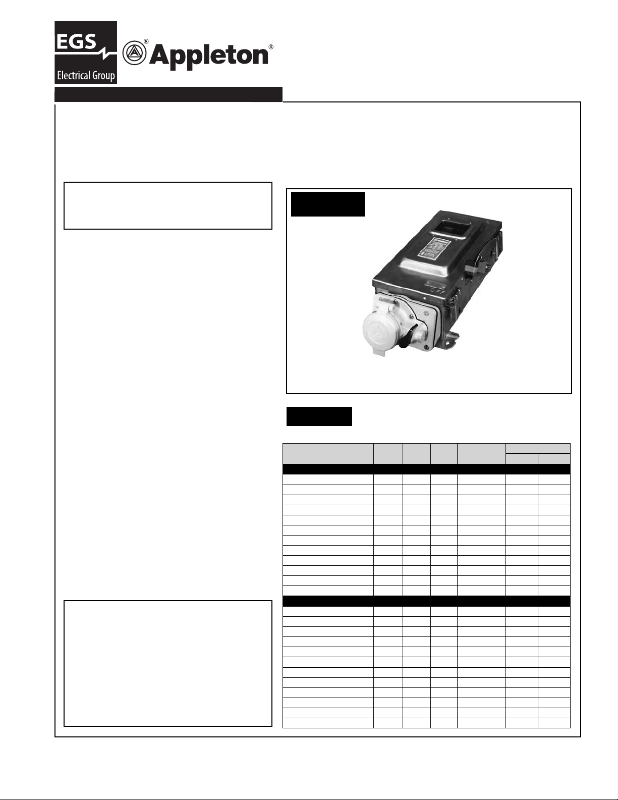
WSRD NEMA 4 Series:
Interlocked Appleton Powertite™ Compatible
Receptacle with heavy duty single throw disconnect switch.
ELECTRICAL RATINGS:
Maximum Voltage: 600VAC at 50-60 Hz*,
250 VDC 30, 60,100 Amperes — Continuous
Line Current not to exceed 80% of fuse rating
employed in other than motor circuits.
* For 400 Hz applications, consult factory.
Compliances:
• UL Listed
• UL50 for Enclosures
• UL1682 for Receptacles
• NEC wire bending space, Table 373-6(b)
• Federal Specifi cation WS865C
• Major automotive specifi cations
STANDARD FEATURES:
• Epoxy coated fi nish on receptacle and switch
housing.
• Factory installed fuse pullers for fusible
disconnect switch.
OPTIONS:
• Electrical Interlocks : 1 N.O. or 1 N.C.
2 N.O. or 2 N.C.
Except as expressly provided by Appleton
Electric LLC (Appleton) in writing, Appleton
products are intended for ultimate purchase
by industrial users and for operation by persons trained and experienced in the use and
maintenance of this equipment and not for
consumers or consumer use. Appleton
warranties do not extend to, and no reseller
is authorized to extend Appleton's warranties
to, any consumer.
FIGURE A
WSRD SERIES
TABLE A
Shown Above:
Non-Fused Version Catalog Number
WSRD63542N4WSD
HORSEPOWER RATING:
DC
Catalog Number
WSRD3352SQ 250 600 30 Fused 7.5 20
WSRD33542SQ 250 600 30 Non-Fused -- 30
WSRD3352WSQ 250 600 30 Fused 7.5 20
WSRD33542WSQ 250 600 30 Non-Fused -- 30
WSRD6352SQ 250 600 60 Fused 15 50
WSRD63542SQ 250 600 60 Non-Fused -- 60
WSRD6352WSQ 250 600 60 Fused 15 50
WSRD63542WSQ 250 600 60 Non-Fused -- 60
WSRD10352SQ 250 600 100 Fused 30 75
WSRD10342SQ 250 600 100 Non-Fused -- 75
WSRD10352WSQ 250 600 100 Fused 30 75
WSRD103542WSQ 250 600 100 Non-Fused -- 75
Stainless Steel Enclosure NEMA 3, 3R, 4, 4X, 12
WSRD3352N4SD 250 600 30 Fused 7.5 20
WSRD33542N4SD 250 600 30 Non-Fused -- 30
WSRD3352N4WSD 250 600 30 Fused 7.5 20
WSRD33542N4WSD 250 600 30 Non-Fused -- 30
WSRD6352N4SD 250 600 60 Fused 15 50
WSRD63542N4SD 250 600 60 Non-Fused -- 60
WSRD6352N4WSD 250 600 60 Fused 15 50
WSRD63542N4WSD 250 600 60 Non-Fused -- 60
WSRD10352N4SD 250 600 100 Fused 30 75
WSRD10342N4SD 250 600 100 Non-Fused -- 75
WSRD10352N4WSD 250 600 100 Fused 30 75
WSRD103542N4WSD 250 600 100 Non-Fused -- 75
Volts
Sheet Metal Enclosure NEMA 12
AC
Volts
Amp
Switch
Type
HP Rating AC
Stand. Max
Rev. B 08/12/08 Page 1
Page 2
APPLICATION:
• Designed to supply power to portable or fi xed
electrical equipment such as welders, infrared
ovens, batch feeders, conveyors and truck and
marine docks.
• Designed to supply three (3) phase, grounded
electrical power to the aforementioned electrical
equipment.
• Designed to provide an interlocked receptacle
for use in ordinary (non-hazardous) locations, as
defi ned by the National Electrical Code (NEC). In
addition, the receptacle is designed such that a
mating plug can only be engaged and disengaged
when the switch handle is in the "OFF" position.
• Ideal for use on shipping docks, ports, and
other "ship to shore" applications.
• Suitable for use in locations that require a degree
of protection from the elements (See TABLE
A). Enclosure cover and receptacle housing are
sealed with gaskets. The receptacle housing fl ip
cover is gasketed to seal against the housing.
In addition, mating plugs can be engaged to the
receptacle face to provide weatherproof union,
SHORT CIRCUIT RATING FUSED/
NONFUSED:
• Suitable for use on a circuit capable of delivering
not more than 10,000 RMS symmetrical Amperes,
600 VAC maximum .
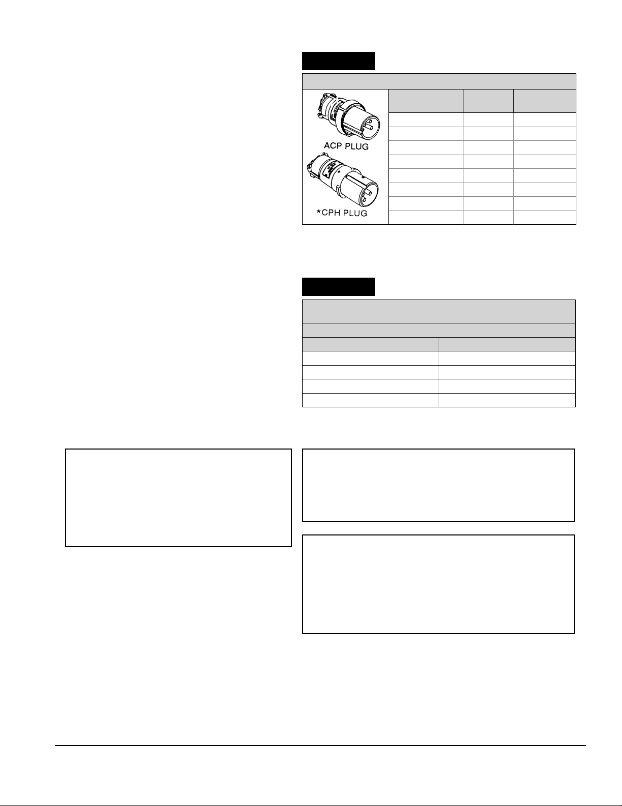
TABLE B
ACP & CPH PLUGS FOR "WSR" RECEPTACLES
CABLE
DIAMETER (In.)
.390 - 1.375 30 ACP3034BC
.500 - .875 30 CPH3034B
.500 - 1.375 60 ACP6034BC
.500 - .750 60 CPH6034A
.750 - 1.00 60 CPH6034B
1.000 - 1.375 60 CPH6034C
.500 - 1.375 60 CPH6034BC
.875 - 1.906 100 ACP1034C
*CPH Plug is rated for NEMA 3R applications only.
TABLE C
TIGHTENING TORQUE — LINE SIDE
DISCONNECT SWITCH LUG SCREWS
SLOTTED HEAD SCREWS
WIRE SIZE (AWG)
#14 -#10 AWG
#8 AWG
#6 - #4 AWG
#3 - #2 AWG
CURRENT
RATING
TORQUE (LB.-IN.)
35
40
45
70
CATALOG
NUMBER
WARNING
• Do not modify these devices in any way.
Replace missing or broken parts with the proper
replacement parts from Appleton Electric, LLC.
• Modifi cation of these devices or substitution
of parts with non-standard parts may result in
serious or fatal personal injury from electrocution.
WARNING
• Turn off power supplying WSRD interlocked receptacle
before and during installation and maintenance.
• Failure to do so may result in serious or fatal injury
from electrocution.
WARNING
• If any part(s) of "WSRD" unit or the mating plug appear
to be missing, broken or show signs of damage:
DISCONTINUE USE IMMEDIATELY!
This condition could cause serious or fatal personal injury
due to electrocution and/or equipment damage. Repair with
the proper replacement part(s) before continuing service.
331114-1 Rev. B 08/12/08 Page 2
Page 3
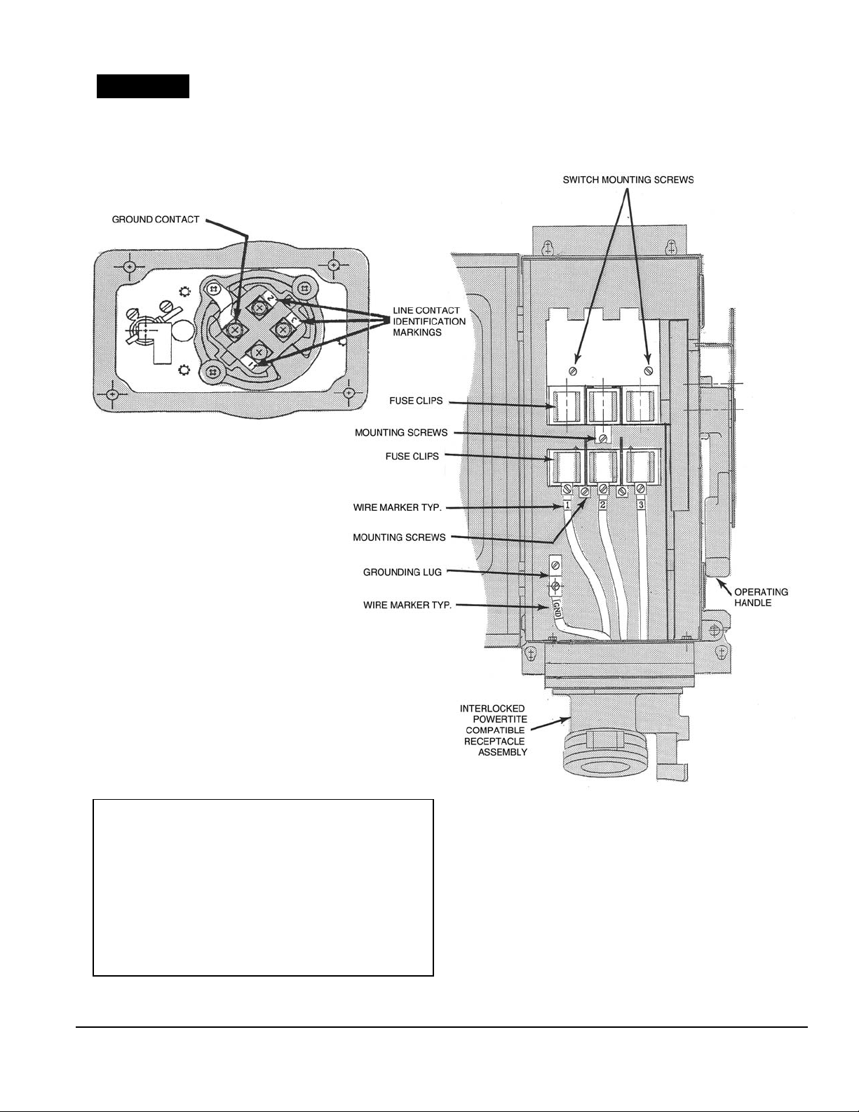
FIGURE B
IDENTIFICATION MARKINGS
REAR VIEW OF RECEPTACLE
ASSEMBLY SHOWING CONTACT
IDENTIFICATION MARKINGS ON
RECEPTACLE INTERIOR.
CONTACT PHASE
WARNING
• Use only cable or wire per the National Electrical Code
(NEC) for the given amp rating of the receptacle.
• Tighten the disconnect switch lug screws to the torques
given in TABLE C and TABLE E for the listed wire ranges.
• Failure to do so may result in over-stressed wire terminations which could cause the conductors to pull out of the
disconnect switch lugs.
fatal injuries due to electrocution.
This could cause serious or
331114-1 Rev. B 08/12/08 Page 3
Page 4

DIMENSIONS: WSRD INTERLOCKED RECEPTACLE
FIGURE C
(ASSEMBLY VIEW WITH COVER OPEN)
Unit shown is Catalog Number WSRD6352SQ (NEMA 12 Version)
Device Rating
30 & 60 Amp 16.75 16.50 22.25
100 Amp 20.75 20.50 26.25
Dimension in Inches
ABC
331114-1 Rev. B 08/12/08 Page 4
Page 5

INSTALLATION INSTRUCTIONS FOR
“WSRD” INTERLOCKED RECEPTACLES
The WSRD receptacles are designed to accept clamping rings of the "ACP" plugs. Clamping rings fi t onto the
receptacle to provide a degree of protection against the
elements and to prevent plug fallout when the receptacle
is in the "OFF" position. When the plug is withdrawn from
the receptacle, the gasketed fl ip cover closes tightly against
the receptacle housing to provide weather-proof conditions
(NEMA TYPE 12 ). Screw cap is required for NEMA TYPE
4 applications.
INSTALLATION
1. PREPARE MOUNTING POSITION:
Owners are responsible for damages or injuries if these
rules are not followed.
WARNING
• Before starting with the installation, make sure the
WSRD interlocked receptacle is suitable for the intended location according to the National Electrical Code or
Canadian Electrical Code.
• If the interlocked receptacle is not suitable, serious
damage and injuries may result.
A. The WSRD interlocked receptacle must be mounted on
four (4) 1/4" maximum diameter steel bolts, securely fastened to wall, column, strut or other vertical structure, in one
plane, and must be capable of supporting the unit, as well
as its associated conduit and wiring.
NOTE: These bolts are not provided with the WSRD interlocked receptacle.
B. Referring to "FIGURE C" for dimensions of the WSRD
interlocked receptacle, prepare the structure for the mounting bolts by drilling, tapping, securing nuts or another method of providing threaded anchors for the bolts.
C. Install the two top bolts leaving 3/16" to 5/16" under the
heads.
• The bolts must be engaged at least fi ve (5) full threads.
2. MOUNTING THE WSRD INTERLOCKED
RECEPTACLE:
Place the interlocked receptacle on the previously prepared
mounting bolts, with the receptacle face
position ( See FIGURE C ). Make sure that the shanks of the
bolts are in the small part of the key-hole slot in the mounting
bracket. Install the two lower bolts. Tighten mounting bolts to
18-20 lb.-ft. torque to secure assembly in place.
3. OPENING ENCLOSURE COVER:
A. Referring to "FIGURE C", loosen the two (2) door
latches.
B. The cover
C. Note that the cover
the housing
is adequate to service the inside of the unit.
is now free to swing open on its hinges.
➂
is not intended to be removed from
, since the range of travel (swing) of the cover
➃
➂
at the lower-most
①
4. CONDUIT INSTALLATION:
A. Drill appropriate trade size hole in the top of the housing
according to the size of hub used. Drill this hole in the location
suggested in "FIGURE C".
B. Make sure hole is free of all burrs and sharp edges.
C. Install the corresponding hub in this hole according to the
instructions given with the hub kit.
D. At this point, ensure that all hubs are tightened appropriately.
TABLE D
TERMINAL WIRE RANGE AND STRIPPING GUIDE
AMPERE
RATING
30 .63
60 .63
100 .63
STRIP LENGTH (In.) TERMINAL WIRE RANGE (AWG)
CONDUCTOR
A
A
BUILDING WIRE
#14 - #2 (Cu)
#6 - #2 (Cu)
#4 - #1/0 (Cu)
LINE CONDUCTORS
GROUNDING CONDUCTOR
5. WIRING:
A. Referring to "FIGURE C", feed line side wiring into housing
through hub opening. Note - wiring must be rated 60
➃
deg. C. or 75 deg. C. copper.
B. Strip the individual conductors per "TABLE D".
C. Connect wires to the proper disconnect switch lugs
loosening, but not removing, lug screws
including all strands into lugs according to your established
wiring scheme. Tighten lug screws
shown in "TABLE C". Please note the wire markers on the
wires
switch lugs
identifi cation markings found on the back of the receptacle
contact block. Refer to "FIGURE B".
connected between the receptacle ➇ and disconnect
➆
. These wire markers correspond to the contact
➄
➅
. Insert conductors
➅
to the appropriate value
➄
by
6. ELECTRICAL TESTING:
All wiring must be checked and tested to ensure that all circuits
are according to plan and that there are no unwanted opens,
shorts or grounds. Do not apply power until the following
steps are completed:
A. Test to verify correct phasing and ground connections.
B. Test insulation resistance by meggering, high voltage or hi-
pot test, to be sure the system does not have any short circuits
or unwanted grounds.
331114-1 Rev. B 08/12/08 Page 5
Page 6

7. CLEAN COVER AND HOUSING:
Before closing the cover ➂, it is strongly recommended that
all dirt, debris and other foreign materials be removed from
the interior.
• This action should be taken to help eliminate the possibility
of unwanted shorts or grounds.
• Make sure the cover gasket surface is clean and free of any
tears or damage.
• Clean the mating surface of the housing
manner as the enclosure cover
➂
.
in the same
➃
8. CLOSE ENCLOSURE COVER:
A. Close the cover ➂.
B. Engage latches
➁
.
9. POWER:
With all electrical tests successfully completed, the door
latched closed and the receptacle turned "OFF", power may
be applied to the WSRD unit.
10. OPERATION:
A. The WSRD interlocked receptacle can now be turned to
the "ON" position by lifting the operating handle
upper-most position.
Note that the WSRD interlocked receptacle cannot be
turned "ON" without a mating plug engaged.
• SAFETY FEATURE - The receptacle is interlocked to the
operating handle mechanism so that a mating plug cannot be
removed when the switch is in the "ON" position.
B. A hole is provided in the housing lock-out ➈ and operat-
ing handle
prevent unauthorized movement of the operating handle
from the "OFF" position.
for the use of a padlock ( See "FIGURE C" ) to
➉
to the
➉
➉
11. MAINTENANCE:
A. INSPECTION: Complete unit must be inspected regularly.
Schedule of inspections is determined by frequency of use
and environmental conditions.
• It is recommended that inspections be carried out at
least once a year.
WARNING
• If any part(s) of the "WSRD" unit or the mating plug
appear to be missing, broken or show signs of damage:
DISCONTINUE USE IMMEDIATELY!
This condition could cause serious or fatal personal injury
due to electrocution and/or equipment damage. Repair with
the proper replacement part(s) before continuing service.
DURING THE INSPECTIONS, PERFORM AT LEAST
THE FOLLOWING:
1. Electrical power supplying the WSRD interlocked receptacle
must be turned "OFF" before performing maintenance.
2. Inspect all conductor terminations for secureness.
• Confi rm torque values given in "TABLE C" and "TABLE E".
• Discoloration due to excessive heat is an indication of
possible problems and should be thoroughly
investigated and repaired as necessary.
3. Check grounding and bonding effectiveness/continuity.
• Retorque connections to original values.
04.
Check gaskets for damage. Replace as necessary.
05.
Check all hubs for tightness and retorque as necessary.
06.
Clean interior of all foreign materials.
07.
Make sure all openings are closed.
08.
Make sure that receptacle assembly fl ip-cover 11 seals
againts the receptacle housing.
09.
Make sure the receptacle assembly nameplate located
on the outside of the cover remains clean and legible.
• Do not paint nameplate
10. Make sure the assembly labels located on the inside of
the cover remain clean and legible.
• It is recommended that an electrical preventive maintenance program, such as found in the National Fire
Protection Bulletin NFPA 70B, be followed in addition to
the above.
.
B. DISCONNECT SWITCH:
Disconnect switches occasionallt fail with use and need to
be replaced.
The disconnect switch used in this receptacle must only be
replaced with the same type and brand as factory installed.
Doing so will not affect the UL Listing.
To replace disconnect switch -
• Referring to "FIGURE C", loosen the line and load side lug
screws h of the disconnect switch and remove wires from
the switch. Take note of the orination of these wires for proper
reassembly. Also note that the wires i that connect the
recptacle to either the disconnect switcch directly (non-fused
version), or connect the receptacle to the fuse base (fused
version) are numbered according to the phase location (See
"FIGURE B").
• Remove disconnect switch and fuse base (if applicable)
mounting screws mountin screws
switch 12 and fuse base 13 (if applicable).
• Replace disconnect switch and fuse base, if applicable, with
the appropriate switch kit as shown in "TABLE E", reversing
the steps taken to remove them. Make sure to reconnect the
wires to the same locations as before disassembly. Replace
fuses, if necessary, for fused receptacle.
used in this interlocked receptacle is not replaceable. In case
of disconnect switch failure, entire unit must be replaced.
TABLE F
Appleton
Disconnect Switch
Cat. No.
WSRNT30F Fused WSRD3352SQ
WSRNT30U Non-Fused WSRD33542SQ
WSRNT60F Fused WSRD6352SQ
WSRNT60U Non-Fused WSRD63542SQ
WSRNT100F Fused WSRD10352SQ
WSRNT100U Non-Fused WSRD103542SQ
• Torque the mounting screw l to 15-20 lb. -in. to secure disconnect switch and fuse base, if applicable, in place.
• Torque the lug screw h to the appropriate value shown in
"TABLE C" and "TABLE F".
SWITCHING KITS
Switch Type Assembly Used In
14
. Remove disconnect
331114-1 Rev. B 08/12/08 Page 6
Page 7

C. RECEPTACLE ASSEMBLY:
The receptacle assemblies shown in "Table F" can be
replaced without affecting the U.L. Listing.
To replace the receptacle assembly -
• Referring to "FIGURE C", loosen the load side lug screws
of the disconnect switch 12 or fuse base 13, (if applicable),
➅
and remove wires.
• Remove the four
16
that fasten the assembly to the housing ➃. Support the
(4)
assembly so that it does not fall from unit.
• Do not allow unit to be used until problem is
corrected.
receptacle assembly mounting screws
• Place the appropriate wires into the correct lug locations
and tighten lug screws to the appropriate value shown in
"TABLE E".
• Test the unit for proper function by performing the following
tasks: ELECTRICAL POWER MUST BE TURNED "OFF"
BEFORE PERFORMING TESTS. Close the cover
throw the switch to the "ON" position to make sure that no
➂
and
interference between new receptacle assembly and switch
exists. Also verify that a mating plug can not be removed
from the receptacle when the switch is in the "ON" position.
If unit functions properly, it can be returned to service. If unit
does not function properly, check the mounting of the receptacle assembly to the housing.
TABLE E
When fi nished with installation, fi le and retain
these instructions for future reference during
inspection and maintenance.
• Remove the old receptacle assembly and replace it with the
new unit. Replacing the unit can be accomplished by reversing the steps needed to remove it. Tighten the four (4) receptacle assembly mounting screws
unit to housing.
TABLE F
REFERENCE
NUMBER
1
2
"WSRD" INTERLOCKED RECEPTACLE REPLACEMENT PARTS
AMPACITY DESCRIPTION PART NUMBER
30
60
100
30
60
100
30 RECEPTACLE ASSEMBLY - 3W - 4P WRDK3034 1
60 RECEPTACLE ASSEMBLY - 3W - 4P WRDK6034 1
100 RECEPTACLE ASSEMBLY - 3W - 4P WRDK1034 1
16
to 19-25 Ib.-in. to secure
ELECTRICAL INTERLOCK, 1 N.O., 1 N.C. WSAUX1 1 WSRD3352SQ &
ELECTRICAL INTERLOCK, 2 N.O., 2 N.C. WSAUX2 1 WSRD33542SQ
ELECTRICAL INTERLOCK, 1 N.O., 1 N.C. WS30AUX1 1 WSRD3352N4SD &
ELECTRICAL INTERLOCK, 2 N.O., 2 N.C. WS30AUX2 1 WSRD33542N4SD
ELECTRICAL INTERLOCK, 1 N.O., 1 N.C. WSAUX1 1 WSRD6352SQ &
ELECTRICAL INTERLOCK, 2 N.O., 2 N.C. WSAUX2 1 WSRD63542SQ
ELECTRICAL INTERLOCK, 1 N.O., 1 N.C. WS60AUX1 1 WSRD6352N4SD &
ELECTRICAL INTERLOCK, 2 N.O., 2 N.C. WS60AUX2 1 WSRD63542N4SD
ELECTRICAL INTERLOCK, 1 N.O., 1 N.C. WSAUX1 1 WSRD10352SQ &
ELECTRICAL INTERLOCK, 2 N.O., 2 N.C. WSAUX2 1 WSRD103542SQ
ELECTRICAL INTERLOCK, 1 N.O.,1 N.C. WS100AUX1 1 WSRD10352N4SD &
ELECTRICAL INTERLOCK, 2 N.O., 2 N.C. WS100AUX2 1 WSRD103542N4SD
Switching Kit - Fused WSRNT30F 1 WSRD3352SQ
Switching Kit - Non-Fused WSRNT30U 1 WSRD33542SQ
Switching Kit - Fused WSRNT60F 1 WSRD6352SQ
Switching Kit - Non-Fused WSRNT60U 1 WSRD63542SQ
Switching Kit - Fused WSRNT100F 1 WSRD10352SQ
Switching Kit - Non-Fused WSRNT100U 1 WSRD103542SQ
TIGHTENING TORQUE — LINE SIDE
DISCONNECT SWITCH LUG SCREWS
SLOTTED HEAD SCREWS
WIRE SIZE (AWG)
#14 -#10 AWG
#8 AWG
#6 - #4 AWG
#3 - #2 AWG
QUANTITY PER
ASSEMBLY
TORQUE (LB.-IN.)
35
40
45
70
ASSEMBLY USED IN
WSRD3352SQ&
WSDR33542SQ
WSRD3352N4SD
WSDR33542N4SD
WSRD6352SQ
WSRD63542SQ
WSRD6352N4SD
WSRD63542N4SD
WSRD10352SQ
WSRD103542SQ
WSRD10352N4SD
WSRD103542N4SD
All statements, technical information and recommendations contained herein are based on information and tests we
believe to be reliable. The accuracy or completeness thereof are not guaranteed. In accordance with Appleton Electric, LLC
"Terms and Conditions of Sale", and since conditions of use are outside our control, the purchaser should determine the suitability of the product for his intended use and assume all risk and liability whatsoever in connection herewith.
331114-1 Rev. B 08/12/08 Page 7
 Loading...