

Appleton Rigmaster LED Series Luminaires, Class I, Division 2, 650609-000 Instruction Sheet
Page 1

650609-000 INSTRUCTION SHEET
Installation Instructions for the Appleton™ Rigmaster™ LED Luminaire
FOR PROPER AND SAFE INSTALLATION OF THIS PRODUCT, PLEASE READ THE FOLLOWING INSTRUCTIONS.
Product Safety
Signal Words Defined
DANGER indicates a hazardous situation which, if not avoided, will result in death or serious injury. WARNING indicates a hazardous situation
which, if not avoided, could result in death or serious injury. CAUTION indicates a hazardous situation which, if not avoided, could result in minor or
moderate injury. NOTICE is used to address practices not related to physical injury.
Safety Instructions for Luminaire
WARNING:
• Before installation, ensure that the unit complies with the hazardous area classication. Refer to luminaire nameplate, located on
exterior of housing body, for suitability in specic hazardous locations.
• Do not open or remove luminaire when supply is ON.
• Do not use luminaire on ungrounded systems. Failure to ground this luminaire can result in an electric shock, which may be fatal.
• Disconnect the luminaire from the supply circuit before opening to reduce the risk of ignition in hazardous atmospheres. Keep
tightly closed when in operation.
• Do not mount near gas or electric heaters.
• De-energize the unit ve (5) minutes before opening.
• Use two safety cables for installations experiencing high vibrations.
CAUTION:
• Do not look directly at the LEDs when energized.
• Lens cleaning instructions: Wipe/clean from the outside only with a moist cloth. (Beware of electrostatic charges.)
• When installing in a hazardous location, it is necessary that the reector, lens, and all certied conduit plugs be in place and
tightened securely to the housing.
NOTICE:
• Do not touch the LEDs; touching could leave oily deposits, causing hot spots and potential premature failure.
• The LED lens should be cleaned periodically from the outside only with a moist cloth to maintain lighting efciency.
• The use of accessory equipment not recommended by the manufacturer may cause an unsafe condition.
• This luminaire is designed for and should be installed with hazardous locations wiring method required in accordance with the
National Electrical Code
• This product must be installed in accordance with the applicable installation code by a person familiar with the construction and
operation of the product and hazards involved.
®
/Canadian Electrical Code and all applicable local codes.
Applications/Intended Use
• Make sure to tighten unused close-up plugs after applying TLNC4 grease. TLNC4 grease shall be applied in 3 lines, spaced
approximately 120 degrees apart, perpendicular to the threads.
• Areas where ammable gases and vapors are present under conditions dened by the ratings below.
• Areas of low clearance, low ceiling heights, or where luminaire weights must be minimized.
• Non-hazardous locations where severe weather conditions, excessive moisture, dirt, dust, corrosive atmospheres, and high
ambient temperatures are encountered.
• Where exible cord is used, it should be approved for extra hard, wet location usage and shall have a separate ground conductor.
Appleton • 1.800.621.1506 • www.appletonelec.com 650609-000 Rev. 03 11/02/20 • Page 1 of 24
Page 2

Agency Ratings : (NEC/CEC)
• Class I, Division 2, Groups A, B, C, D • Class I, Zone 2, Group II C
• Class II, Division 1, Groups E, F, G • Zone 20
• Class III • Wet Locations
• Type 3R, 4 & 4X • Simultaneous Exposure
• IP66
• Marine Outside Type (Salt Water) (For installations in USA only)
NOTES:
Refer to the product nameplate, located on the housing body, for details.
Dimensions/Details
LUMINAIRE DIMENSIONS
FIGURE 1: RIGMASTER 2 FT. LUMINAIRE
FIGURE 2: RIGMASTER 4 FT. LUMINAIRE
650609-000 Rev. 03 11/02/20 • Page 2 of 24Appleton • 1.800.621.1506 • www.appletonelec.com
Page 3

Mounting Instructions
1. Make sure power is disconnected before installing the luminaire.
2. Determine appropriate mounting distance between mounting holes for your application.
3. Use bolts (not supplied) appropriate for the structural support member.
4. Secure luminaire to structural support element having through holes that can handle the weight of the luminaire in accordance with
local building code and all other code requirements.
5. Tighten the bolts to secure the luminaire in place.
Mounting Brackets
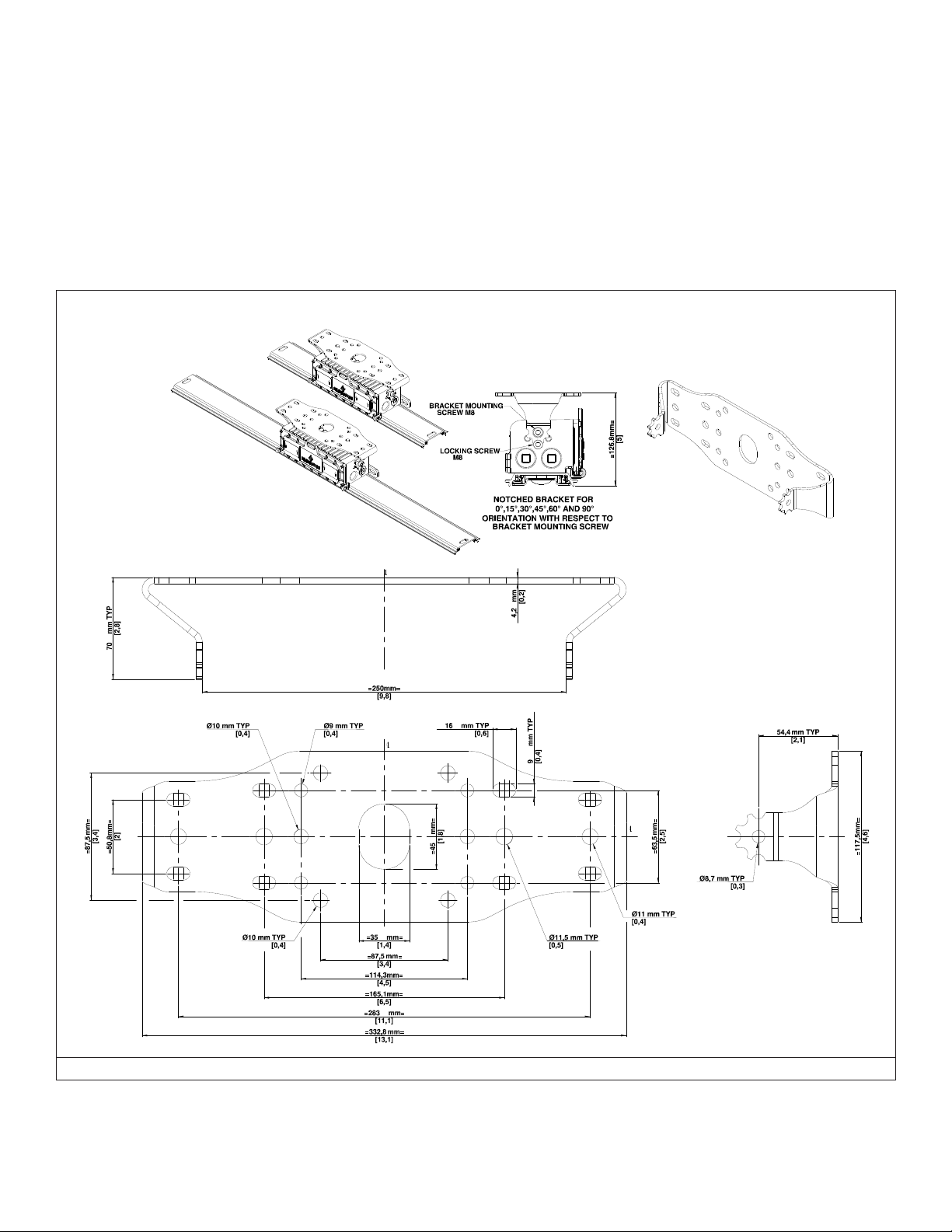
SMALL SWIVEL BRACKET (RMSSB)
1. Make sure power is disconnected & circuit is de-energized before installing the bracket.
2. Determine appropriate mounting distance between holes on the brackets for your application. Refer to Figure 3.
3. Secure RMSSB bracket to structural support member with appropriate bolts (not supplied) that can handle the weight of luminaire in accordance
with local building code and all other code requirements.
4. Raise luminaire to mounted RMSSB bracket and secure it using M8 washer and bracket mounting screw (M8) supplied with the bracket on both
sides. Refer to Figure 3 for hole locations.
5. Align the luminaire to the desired aiming position with your free hand and use Locking screw (M8) supplied with the bracket to hold at that position.
Refer to Figure 3.
6. Tighten all the screws to secure the luminaire in place with a torque of 15 N.m (133 Lb.in)
FIGURE 3: MOUNTING OPTIONS – RMSSB BRACKET
650609-000 Rev. 03 11/02/20 • Page 3 of 24Appleton • 1.800.621.1506 • www.appletonelec.com
Page 4
LARGE SWIVEL BRACKET (RMLSB)
1. Make sure power is disconnected & circuit is de-energized before installing the bracket.
2. Determine appropriate mounting distance between holes on the brackets for your application. Refer to gure 4.
3. Secure RMLSB bracket to structural support member with appropriate bolts (not supplied) that can handle the weight of luminaire
in accordance with local building code and all other code requirements.
4. Raise luminaire to mounted RMLSB bracket and secure it using M8 washer and bracket mounting screw (M8) supplied with the
bracket on both sides. Refer to gure 4 for hole locations.
5. Align the luminaire to the desired aiming position with your free hand and use Locking screw (M8) supplied with the bracket to hold
at that position. Refer to gure 4.
6. Tighten all the screws to secure the luminaire in place with a torque of 15 N.m (133 Lb.in)
FIGURE 4: MOUNTING OPTIONS – RMLSB BRACKET
650609-000 Rev. 03 11/02/20 • Page 4 of 24Appleton • 1.800.621.1506 • www.appletonelec.com
Page 5
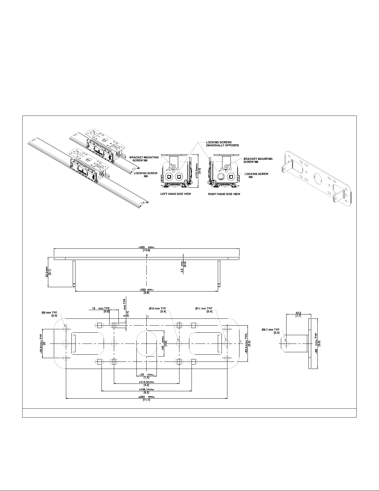
LOW PROFILE FIXED BRACKET (RMLPB)
1. Make sure power is disconnected and circuit is de-energized before installing the bracket.
2. Determine appropriate mounting distance between holes on the brackets for your application. Refer to gure 5.
3. Secure RMLPB bracket to structural support member with appropriate bolts (not supplied) that can handle the weight of luminaire
in accordance with local building code and all other code requirements.
4. Raise luminaire to mounted RMLPB bracket and secure using M8 washer and bracket mounting screw (M8) supplied with the
bracket on both sides. Refer to gure 5.
5. Use locking screw (M8) supplied with the bracket such that they are diagonally opposite to each other on either side. Refer to gure
5 for hole locations. Make sure bracket is locked to its position.
6. Tighten all the screws to secure the luminaire in place with a torque of 15 N.m (133 Lb.in)
FIGURE 5: MOUNTING OPTIONS – RMLPB BRACKET
650609-000 Rev. 03 11/02/20 • Page 5 of 24Appleton • 1.800.621.1506 • www.appletonelec.com
Page 6

TABLE 1: MOUNTING BRACKET COMPATIBILITY CHART FOR RETROFIT INSTALLATIONS
Appleton Part Number
Manufacturer Part Number
RMSSB
Small Swivel Bracket
RMLSB
Large Swivel Bracket
RMLPB
Low Profile Fixed Bracket
Crouse Hinds DP1057MTK X X
Dialight
LTXW4 X X
LTXW4LP X X
AZZ™ Rigalite 53050 X X
Appleton™ Viamaster™ GRFC75A X
Wiring
WARNING: The luminaire must be grounded as required by the National Electrical Code (Paragraph 410.21 and Article 250) or
Canadian Electrical Code (Rule 30-500 and Section 10). Verify that ground continuity has been established by using an Ohm meter or
other suitable testing equipment before energizing the luminaire. Failure to properly ground the luminaire will create an electric shock
hazard, which can cause serious injury or death.
Please use supply wires with temperature rating 90°C or above
Wiring the Rigmaster™ LED Luminaire with Wire Nut Option
Note: Each wire nut can accept 2 # AWG12 (user wires) with 1 # AWG18 wires (Luminaire wire). Use the appropriate wire gauge based on the
application. Refer to the table below for power system application.
TABLE 2
POWER SYSTEM BLACK WHITE GREEN
L-N AC POWER SYSTEM HOT / LINE NEUTRAL GROUND
L-L AC POWER SYSTEM HOT 1 / LINE 1 HOT 2 / LINE 2 GROUND
DC POWER SYSTEM +VE -VE GROUND
1. Make sure power is disconnected before wiring the luminaire.
2. A. Wiring with Cable: Strip the cable outer jacket as required. Strip the insulation of individual wire by approximately
13 mm (0.5 in)
B. Wiring with Individual Wires: Strip the insulation of individual wire by approximately 13 mm (0.5 in)
3. For standard Wiring:
A. For Luminaire with ¾ inch hub size - Connect electrical power supply leads to the 3 wire conductors coming out of
wiring compartment with the help of wire nuts supplied with luminaire by holding wires together with even ends: see gure
6. After completing the wiring, insert wire nuts in wiring compartment through the Conduit / Cable entry hole. For Wiring
diagram refer Figure 7, 8.
B. For Luminaire with ½ inch OR M20 hub size-
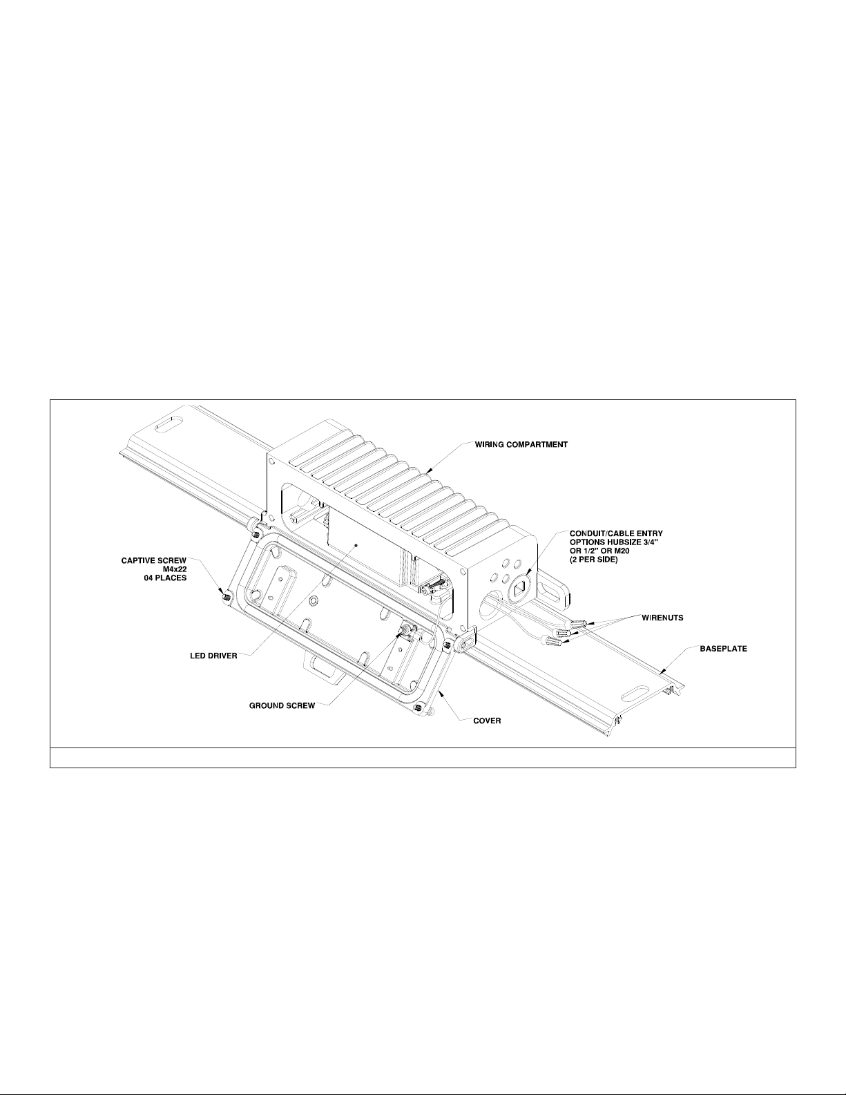
1. Open the luminaire wiring compartment by loosening the four captive screws. Allow the cover to swing open,
enabling access to the wiring compartment. See Figure 6. Pull in the luminaire’s supply input side driver wires (by
removing wire nuts) through the cable entry hole, inside the wiring compartment.
2. Pull in the facility electrical supply wires through the same conduit entry hole.
3. Connect electrical power supply leads to the 3 wire conductors with the help of wire nuts by holding wires together
with even ends. For Wiring diagram refer Figure 7, 8.
4. Check all connections for continuity and ground integrity and close the luminaire wiring compartment cover.
5. Tighten the four captive screws by applying a torque of 2.25 N.m (20 Lb.in) using the sequence shown as in gure 9.
Make sure wires do not pinch between cover and wiring compartment while closing.
650609-000 Rev. 03 11/02/20 • Page 6 of 24Appleton • 1.800.621.1506 • www.appletonelec.com
Page 7
4. For through feed Wiring (for all conduit sizes):
A. Open the luminaire wiring compartment by loosening the four captive screws. Allow the cover to swing open,
enabling access to the wiring compartment. See Figure 6. Pull in the luminaire’s supply input side driver wires (by
removing wire nuts) through the cable entry hole, inside the wiring compartment.
B. Pull in the facility electrical supply wires from both sides through the conduit entry holes on luminaire input side.
C. Connect electrical power supply leads to the respective wires with the help of wire nuts supplied with luminaire by
holding wires together with even ends. For Wiring diagram refer Figure 7, 8.
D. Check all connections for continuity and ground integrity and close the luminaire wiring compartment cover.
E. Tighten the four captive screws by applying a torque of 2.25 N.m (20 Lb.in) using the sequence shown as in gure 9.
Make sure wires do not pinch between cover and wiring compartment while closing.
5. Apply TLNC4 grease on plugs (3 supplied) in 3 lines, spaced approximately 120 degrees apart, perpendicular to the threads. After
applying TLNC4 grease close all unused conduit entries with plugs. Apply torque of 45 N.m (400 Lb.in.) for 3/4" NPT plug, 28 N.m
(250 Lb.in.) for ½" NPT plug and 25 N.m (225 Lb. in.) for M20 plug.
6. For continuous row mounting, below mentioned number of luminaires can be connected.
Maximum 28 luminaires of 4300 lm. connected in series
Maximum 15 luminaires of 7600 lm. connected in series
7. Power can now be applied to the luminaire.
FIGURE 6: RIGMASTER LUMINAIRE WITH WIRE NUT OPTION
650609-000 Rev. 03 11/02/20 • Page 7 of 24Appleton • 1.800.621.1506 • www.appletonelec.com
Page 8
Wiring Diagrams
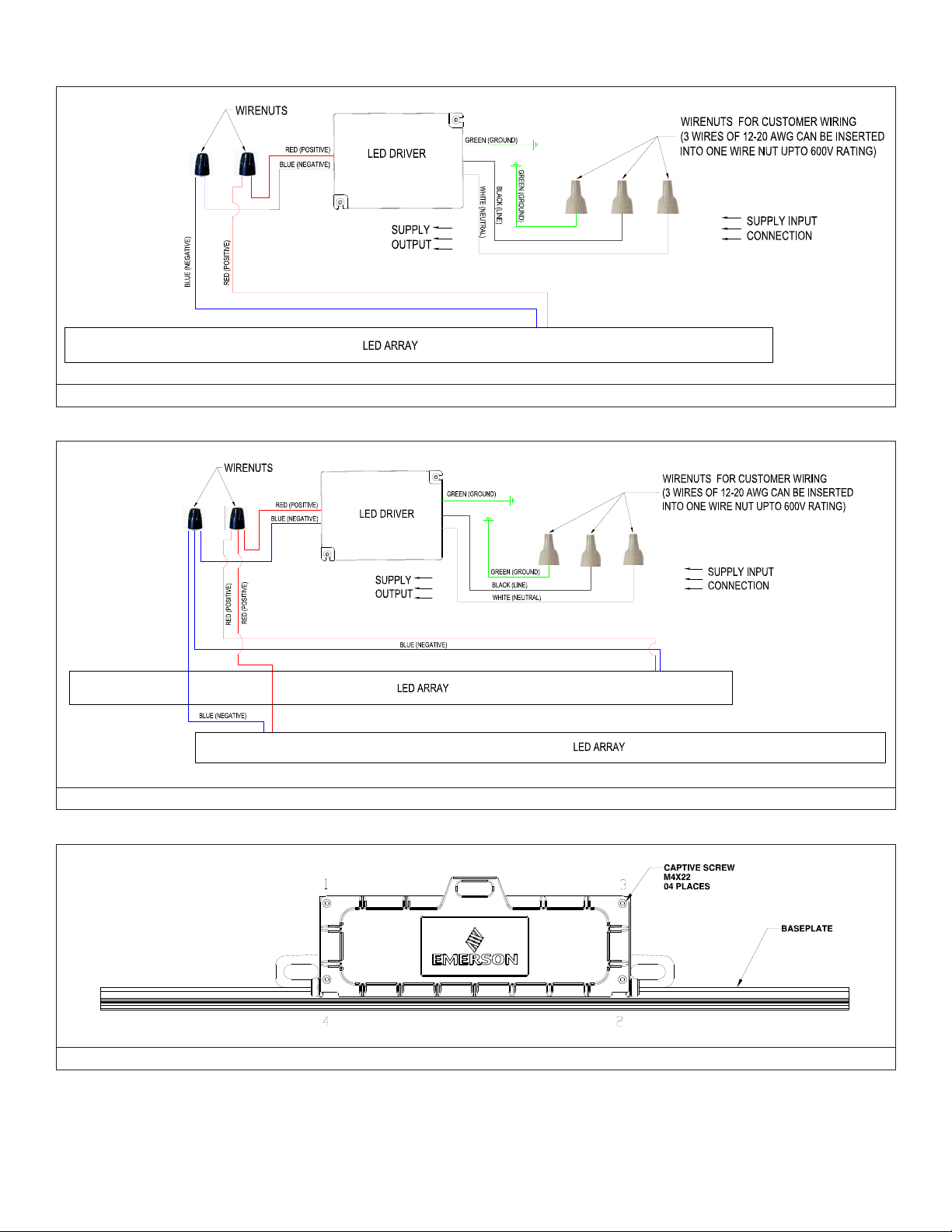
FIGURE 7: FOR RIGMASTER 2 FT WITH WIRE NUTS FOR CUSTOMER WIRING
FIGURE 8: FOR RIGMASTER 4 FT WITH WIRE NUTS FOR CUSTOMER WIRING
FIGURE 9: SCREW TIGHTENING SEQUENCE
650609-000 Rev. 03 11/02/20 • Page 8 of 24Appleton • 1.800.621.1506 • www.appletonelec.com
Page 9

Wiring the Rigmaster™ LED Luminaire with Fixed Screw Terminal Option
Note: See the product nameplate for supply wire requirements. The terminal block can accept 12-20 AWG wire. Use the appropriate wire gauge based
on the application. Refer table below for power system application.
TABLE 3
POWER SYSTEM L N PE
L-N AC POWER SYSTEM HOT / LINE NEUTRAL GROUND
L-L AC POWER SYSTEM HOT 1 / LINE 1 HOT 2 / LINE 2 GROUND
DC POWER SYSTEM +VE -VE GROUND
1. Make sure power is disconnected before wiring the luminaire.
2. Open the luminaire wiring compartment by loosening the four captive screws. Allow the cover to swing open, enabling access to the wiring
compartment. see gure 10.
3. A. Wiring with Cable
1. Strip the cable outer jacket as required.
2. Insert the cable through the conduit entry (with appropriate cable tting attached) to the luminaire wiring compartment.
B. Wiring with Individual Wires
1. Run conductors down through the conduit to the luminaire wiring compartment.
4. Strip the individual wires by approximately 5 mm (0.2 in) and insert them into the proper terminal block connections. The connection points are
identied on the terminal block as: "L" = Line, "N" = Neutral, and "PE" = Ground. Tighten down the terminal block screws onto the wire with torque
of 0.75 N.m (6.5 Lb.in) See Figure 10.
5. Check all connections for continuity and ground integrity.
6. Once the terminal block is wired to incoming power, close the luminaire wiring compartment cover.
7. Tighten the four captive screws by applying a torque of 2.25 N.m (20 Lb.in) using the sequence shown as in gure 9. Make sure wires do not pinch
between cover and wiring compartment when closing.
8. Apply TLNC4 grease on plugs (3 supplied) in 3 lines, spaced approximately 120 degrees apart, perpendicular to the threads. After applying TLNC4
grease close all unused conduit entries with plugs. Apply torque of 45 N.m (400 Lb.in.) for 3/4" NPT plug, 28 N.m (250 Lb.in.) for ½’" NPT plug and
25 N.m (225 Lb. in.) for M20 plug.
9. For continuous row mounting below mentioned number of luminaires can be connected.
Maximum 28 luminaires of 4300 lm. connected in series.
Maximum 15 luminaires of 7600 lm. connected in series
10. Power can now be applied to the luminaire.
FIGURE 10: RIGMASTER LUMINAIRE WITH SCREW TERMINAL OPTION
650609-000 Rev. 03 11/02/20 • Page 9 of 24Appleton • 1.800.621.1506 • www.appletonelec.com
Page 10

Wiring Diagrams
FIGURE 11: FOR RIGMASTER 2 FT WITH TERMINAL BLOCKS FOR CUSTOMER WIRING
FIGURE 12: FOR RIGMASTER 4 FT WITH TERMINAL BLOCKS FOR CUSTOMER WIRING
650609-000 Rev. 03 11/02/20 • Page 10 of 24Appleton • 1.800.621.1506 • www.appletonelec.com
Page 11

TABLE 4: RECOMMENDED APPLETON™ CABLE CONNECTORS - REFER TO THE TABLE BELOW
COMPATIBLE CORD GRIPS
Appleton Part Number Recommendation
CG3150 Suitable for through wiring using either side (2 CG on either side)
CG6250 Suitable for through wiring using either side (2 CG on either side)
CG5075 Suitable for through wiring using either side (2 CG on either side)
CG3150S Suitable for through wiring using either side (2 CG on either side)
CG6250S Suitable for through wiring using both sides (1 CG on each side)
CG5075S Suitable for through wiring using both sides (1 CG on each side)
COMPATIBLE TRAY CABLE CONNECTORS
Appleton Part Number Recommendation
TC050055 Suitable for through wiring using both sides (1 connector on each side)
Installation of the Safety Cable
TABLE 5: SAFETY CABLE SPECIFICATION
Cable Diameter Length Tolerance
4 mm (5/32 in.) 1219 mm (48 in.) +50/-25 mm (+2.0/-1.0 in.) 316 Stainless Steel 113 kg Max. (250 lbs. Max.)
FIGURE 13: SAFETY CABLE
1. Install luminaire with supplied bracket using desired mounting means.
2. Insert closed loop of safety cable through a minimum of two retention slots on the luminaire. For a more secure installation, it is
recommended to loop the cable through the slots provided on the cover, wiring compartment and baseplate. (See gure 14,15)
3. Insert eyelet (carabiner clip) through the center of the closed end loop and pull until the end is tight.
4. Attach safety cable to desired support structure using eyelet (carabiner clip) end.
5. Tighten the threaded locknut (gate) until tight.
Material Carabiner/
Sleeve/Cable
Safe Working Load at 5:1
Safety Factor
650609-000 Rev. 03 11/02/20 • Page 11 of 24
Page 12

FIGURE 14: RIGMASTER 2 FT. LUMINAIRE WITH SAFETY CABLES
FIGURE 15: RIGMASTER 4 FT. LUMINAIRE WITH SAFETY CABLES
Except as expressly provided by Appleton Grp, LLC (Appleton), Appleton products are intended for ultimate purchase by industrial users and for operation by persons trained and experienced in the use and maintenance of this equipment
and not for consumers or consumer use. Appleton warranties DO NOT extend to, and no reseller is authorized to extend Appleton’s warranties to any consumer.
While every precaution has been taken to ensure accuracy and completeness in this manual, Appleton Grp, LLC. assumes no responsibility, and disclaims all liability for damages resulting from use of this information or for any errors or
omissions. Specications are subject to change without notice. The Appleton and Emerson logos are registered in the U.S. Patent and Trademark Ofce. All other product or service names are the property of their registered owners.
©2020 Appleton Grp, LLC. All rights reserved.
650609-000 Rev. 03 11/02/20 • Page 12 of 24
Page 13

650609-000 FEUILLE D'INSTRUCTION
Instructions d’Installation du Luminaire à LED Appleton™ Rigmaster™
POUR UN INSTALLATION CORRECTE ET SÛRE DE CE PRODUIT, VEUILLEZ LIRE LES INSTRUCTIONS SUIVANTES.
Sécurité du Produit
Définitions des termes de mise en garde
DANGER indique une situation dangereuse qui, si elle n’est pas évitée, entraînera la mort ou des blessures graves.
AVERTISSEMENT indique une situation dangereuse qui, si elle n’est pas évitée, pourrait entraîner la mort ou des blessures graves.
ATTENTION indique une situation dangereuse qui, si elle n’est pas évitée, pourrait entraîner des blessures mineures ou modérées.
AVIS est utilisé pour aborder des pratiques non liées à des blessures physiques.
Instructions de Sécurité Pour le Luminaire
AVERTISSEMENT:
• Avant l’installation, assurez-vous que l’appareil est conforme à la classication de zone dangereuse. Consultez la plaque signalétique du luminaire, située à l’extérieur du corps du boîtier, pour savoir quelle est sa position dans des zones dangereuses spéciques.
• N’ouvrez pas et ne retirez pas le luminaire lorsque l’alimentation est en marche.
• N’utilisez pas le luminaire sur des systèmes non mis à la masse. Ne pas mettre ce luminaire à la masse peut entraîner un choc
électrique pouvant être fatal.
• Déconnectez le luminaire du circuit d’alimentation avant de l’ouvrir pour réduire le risque d’inammation dans les atmosphères
dangereuses. Maintenir hermétiquement fermé en utilisation.
• Ne pas installer à proximité de radiateurs à gaz ou électriques.
• Mettez l’appareil hors tension cinq (5) minutes avant de l’ouvrir.
• Utilisez deux câbles de sécurité pour les installations soumises à de fortes vibrations.
ATTENTION:
• Ne regardez pas directement les luminaires lorsqu’ils sont sous tension.
• Instructions de nettoyage de la lentille : Essuyez / nettoyez de l’extérieur uniquement avec un chiffon humide. (Attention aux
charges électrostatiques).
• Lors d’une installation dans une zone dangereuse, il est nécessaire que le réecteur, la lentille et tous les bouchons de conduit
certiés soient en place et bien serrés sur le boîtier.
AVIS:
• Ne touchez pas au LEDs ; les toucher pourraient laisser des dépôts gras, provoquant des points chauds et une possible défaillance
prématurée.
• La lentille du LED doit être nettoyée périodiquement de l’extérieur uniquement avec un chiffon humide pour maintenir l’efcacité de
l’éclairage.
• L’utilisation d’accessoires non recommandés par le fabricant peut créer des conditions dangereuses.
• Ce luminaire est conçu pour et doit être installé avec la méthode de câblage pour zones dangereuses requise conformément au
Code Electrique National
• Ce produit doit être installé conformément au code d’installation en vigueur par une personne familiarisée avec la construction et le
fonctionnement du produit et des risques qui y sont associés.
®
/ Code Canadien de l’Electricité (CEN / CCE) et à tous les codes locaux applicables.
Applications/Usage Prévu
• Assurez-vous de serrer les bouchons de gros plan non utilisés après avoir appliqué de la graisse TLNC4. La graisse TLNC4 doit
être appliquée en 3 lignes espacées d’environ 120 degrés, perpendiculairement aux ls.
• Les zones où des gaz et des vapeurs inammables sont présents dans des conditions dénies par les indices ci-dessous.
• Les zones où l’espacement est faible, les hauteurs de plafond basses ou les poids des luminaires doivent être minimisés.
• Endroits non dangereux où se rencontrent des conditions météorologiques extrêmes, une humidité excessive, de la saleté, de la
poussière, des atmosphères corrosives et des températures ambiantes élevées.
• Lorsqu’un cordon souple est utilisé, il doit être approuvé pour une utilisation dans des endroits extrêmement durs et humides et
doit comporter un conducteur de terre séparé.
Appleton • 1.800.621.1506 • www.appletonelec.com 650609-000 Rev. 03 11/02/20 • Page 13 of 24
Page 14

Classements d’agence: (NEC/CEC)
• Class I, Division 2, Groups A, B, C, D • Class I, Zone 2, Group II C
• Class II, Division 1, Groups E, F, G • Zone 20
• Class III • Emplacements Humides
• Type 3R, 4 & 4X • Exposition Simultanée
• IP66
• Type marin extérieur (eau salée) (uniquement pour les installations aux États-Unis)
REMARQUES :
Se référer à la plaque signalétique du produit, située sur le corps du boîtier, pour plus de détails.
Dimensions/Détails
DIMENSIONS du LUMINAIRE
FIGURE 1 : RIGMASTER 2 FT LUMINAIRE
FIGURE 2 : RIGMASTER 4 FT LUMINAIRE
650609-000 Rev. 03 11/02/20 • Page 14 of 24Appleton • 1.800.621.1506 • www.appletonelec.com
Page 15

Instructions de montage
1. Assurez-vous que l’alimentation est débranchée avant d’installer le luminaire.
2. Déterminez la distance de montage appropriée entre les trous de xation pour votre utilisation.
3. Utilisez des boulons (non fournis) adaptés à l’élément de support structurel.
4. Fixez le luminaire à l’élément de support structurel ayant des trous. pouvant supporter le poids du luminaire conformément au
code du bâtiment local et à toutes les autres exigences du code.
5. Serrez les boulons pour maintenir le luminaire en place.
Supports de Fixation
Petit Support Pivotant Rigmaster (RMSSB)
1. Assurez-vous que l’alimentation est débranchée et que le circuit est hors tension avant d’installer le support.
2. Déterminer la distance de montage appropriée entre les trous des supports pour votre application. Voir la gure 3.
3. Fixez le support RMSSB à l’élément de support structurel avec des boulons appropriés (non fournis) pouvant supporter le poids du
luminaire conformément au code du bâtiment local et à toutes les autres exigences du code.
4. Soulevez le luminaire sur le support monté RMSSB et xez-le à l'aide de la rondelle M8 et de la vis de montage du support (M8)
fournies avec le support des deux côtés. Reportez-vous à la gure 3 pour connaître l'emplacement des trous.
5. Alignez le luminaire avec la main libre sur la position de visée souhaitée et utilisez la vis de verrouillage (M8) fournie avec le support
pour la maintenir dans cette position. Voir la gure 3.
6. Serrez toutes les vis pour xer le luminaire avec un couple de 15 N.m (133 Lb.in)
FIGURE 3 : OPTIONS DE MONTAGE – SUPPORT RMSSB
650609-000 Rev. 03 11/02/20 • Page 15 of 24Appleton • 1.800.621.1506 • www.appletonelec.com
Page 16

GRAND SUPPORT PIVOTANT Rigmaster (RMLSB)
1. Assurez-vous que l’alimentation est débranchée et que le circuit est hors tension avant d’installer le support.
2. Déterminer la distance de montage appropriée entre les trous des supports pour votre application. Voir la gure 4.
3. Fixez le support RMLSB à l’élément de support structurel avec des boulons appropriés (non fournis) pouvant supporter le poids du
luminaire conformément au code du bâtiment local et à toutes les autres exigences du code.
4. Soulevez le luminaire sur le support monté RMLSB et xez-le à l'aide de la rondelle M8 et de la vis de montage du support (M8)
fournies avec le support des deux côtés. Reportez-vous à la gure 4 pour connaître l'emplacement des trous.
5. Alignez le luminaire avec la main libre sur la position de visée souhaitée et utilisez la vis de verrouillage (M8) fournie avec le support
pour la maintenir dans cette position. Voir la gure 4.
6. Serrez toutes les vis pour xer le luminaire avec un couple de 15 N.m (133 Lb.in)
FIGURE 4 : OPTIONS DE MONTAGE – SUPPORT RMLSB
650609-000 Rev. 03 11/02/20 • Page 16 of 24Appleton • 1.800.621.1506 • www.appletonelec.com
Page 17

SUPPORT FIXE à PROFIL BAS Rigmaster (RMLPB)
1. Assurez-vous que l’alimentation est débranchée et que le circuit est hors tension avant d’installer le support.
2. Déterminer la distance de montage appropriée entre les trous des supports pour votre application. Voir la gure 5.
3. Fixez le support RMLPB à l’élément de support structurel à l’aide des boulons appropriés (non fournis) pouvant supporter le poids
du luminaire conformément au code du bâtiment local et à toutes les autres exigences du code.
4. Soulevez le luminaire sur le support RMLPB et xez-le à l'aide de la rondelle M8 et de la vis de montage (M8) fournies avec le
support des deux côtés. Voir la gure 5.
5. Utilisez la vis de blocage (M8) fournie avec le support de sorte qu’ils soient diagonalement opposés les uns des autres. Reportez-
vous à la gure 5 pour connaître l'emplacement des trous. Assurez-vous que le support est verrouillé à sa position.
6. Serrez toutes les vis pour xer le luminaire avec un couple de 15 N.m (133 Lb.in)
FIGURE 5 : OPTIONS DE MONTAGE – SUPPORT RMLPB
650609-000 Rev. 03 11/02/20 • Page 17 of 24Appleton • 1.800.621.1506 • www.appletonelec.com
Page 18

TABLE 1: TABLEAU DE COMPATIBILITE DES SUPPORTS DE FIXATION POUR MONTAGES ULTERIEURS
Numéro de Pièce Appleton
Fabricant Numéro de Pièce
Crouse Hinds DP1057MTK X X
LTXW4 X X
Dialight
LTXW4LP X X
AZZ™ Rigalite 53050 X X
Appleton™ Viamaster™ GRFC75A X
RMSSB
Petit Support Pivotant
RMLSB
Large Support Pivotant
RMLPB
Support à Profil Bas
Câblage
AVERTISSEMENT : Le luminaire doit être immobilisé conformément au Code National de l’Electricité (Paragraphe 410.21 et
Article 250) ou au Code Canadien de l’Electricité (Règle 30-500 et à la Section 10). Vériez que la continuité de masse a été établie en
utilisant un ohmmètre ou un autre équipement de test approprié avant de mettre le luminaire sous tension. Si vous n’immobilisez pas
correctement le luminaire, vous vous exposez à un risque de choc électrique pouvant entraîner des blessures graves, voire mortelles.
Veuillez utiliser des câbles d’alimentation avec une température de 90°C ou plus
Câblage du luminaire à LED Rigmaster™ avec Option Connecteur Electrique
REMARQUE: Chaque écrou de câble peut accepter 2 # AWG12 (l du circuit d’attaque) avec 1 # AWG18 (l du luminaire). Reportez-vous au tableau
ci-dessous pour l'application du système d'alimentation.
TABLE 2
SYSTÈME D'ALIMENTATION NOIR BLANC VERT
L-N SYSTÈME D'ALIMENTATION en CA CHAUD / LIGNE NEUTRE SOL
L-L SYSTÈME D'ALIMENTATION en CA CHAUD 1 / LIGNE 1 CHAUD 2 / LIGNE 2 SOL
SYSTÈME D'ALIMENTATION en CC +VE -VE SOL
1. Assurez-vous que l'alimentation est débranchée avant de câbler le luminaire.
2. A. Câblage avec câble: Dénudez la gaine extérieure du câble si nécessaire. Dénudez l'isolant de chaque l d'environ
13 mm (0,5 po)
B. Câblage avec des ls individuels: Dénudez l'isolant de chaque l d'environ 13 mm (0,5 po)
3. Pour câblage standard:
A. Pour luminaire avec ¾ pouce de taille de moyeu - Reliez les ls d’alimentation électrique aux conducteurs à 3 ls
sortant du compartiment de câblage à l’aide des écrous fournis avec le luminaire, en tenant les ls ensemble par des
extrémités paires: voir la gure 6. Une fois l’écrou de câblage inséré dans le compartiment de câblage par le conduit /trou
d'entrée de câble. Pour le schéma de câblage, voir Figure 7, 8.
B. Pour luminaire avec taille de moyeu ½ pouce OU M20 -
• Ouvrez le compartiment de câblage du luminaire en desserrant les quatre vis imperdables. Laisser le couvercle s'ouvrir
pour permettre l'accès au compartiment de câblage. Voir la gure 6. Tirez les ls du circuit d’attaque du côté de
l'alimentation du luminaire (en retirant les écrous de l) à travers le trou d'entrée de câble, à l'intérieur du compartiment de
câblage.
• Tirez sur les ls d’alimentation électrique de l’installation à travers le même trou d’entrée du conduit.
• Reliez les ls d’alimentation électrique aux conducteurs à 3 ls à l’aide d’écrous en maintenant les ls ensemble avec des
extrémités paires. Pour le schéma de câblage, voir Figure 7, 8.
• Vériez toutes les connexions pour la continuité et l'intégrité de la mise à la terre et fermez le couvercle du compartiment
de câblage du luminaire.
• Serrez les quatre vis imperdables en appliquant un couple de serrage de 2,25 N.m (20 Lb.in) en suivant la séquence illustrée à la gure 9. Assurez-vous que les ls ne se coincent pas entre le couvercle et le compartiment de câblage lors de la
fermeture.
650609-000 Rev. 03 11/02/20 • Page 18 of 24Appleton • 1.800.621.1506 • www.appletonelec.com
Page 19

4. Pour le câblage traversant (pour toutes les tailles de conduit):
A. Ouvrez le compartiment de câblage du luminaire en desserrant les quatre vis imperdables. Laisser le couvercle s'ouvrir
pour permettre l'accès au compartiment de câblage. Voir la gure 6. Tirez les ls du circuit d’attaque du côté de
l'alimentation du luminaire (en retirant les écrous de l) à travers le trou d'entrée de câble, à l'intérieur du compartiment de
câblage.
B. Tirez les ls d’alimentation électrique de l’installation des deux côtés à travers les trous d’entrée du conduit du côté entrée
du luminaire.
C. Connectez les câbles d’alimentation électrique aux câbles respectifs à l’aide des écrous fournis avec le luminaire en
maintenant les câbles avec les extrémités paires. Pour le schéma de câblage, voir Figure 7, 8.
D. Vériez toutes les connexions pour la continuité et l'intégrité de la mise à la terre et fermez le couvercle du compartiment
de câblage du luminaire.
E. Serrez les quatre vis imperdables en appliquant un couple de 2,25 N.m (20 Lb.in) en respectant la séquence illustrée
à la gure 9. Assurez-vous que les ls ne se coincent pas entre le couvercle et le compartiment de câblage lors de la
fermeture.
5. Appliquez de la graisse TLNC4 sur les bouchons (3 fournis) en 3 lignes espacées d'environ 120 degrés, perpendiculairement aux
ls. Après application de la graisse TLNC4, fermez toutes les entrées de conduit inutilisées avec des bouchons. Appliquez un
couple de serrage de 45 N.m (400 Lb.in) pour un bouchon 3/4 "NPT, 28 N.m (250 Lb.in.) pour un bouchon 1/2" NPT et
25 N.m (225 Lb.) pour un bouchon M20.
6. Pour le montage en rangée continue, le nombre de luminaires indiqué ci-dessous peut être connecté.
28 luminaires maximum de 4300 lm. connecté en série
15 luminaires maximum de 7600 lm. connecté en série
7. Le luminaire peut maintenant être allumé.
FIGURE 6: LUMINAIRE RIGMASTER AVEC CONNECTEUR ELECTRIQUE
650609-000 Rev. 03 11/02/20 • Page 19 of 24Appleton • 1.800.621.1506 • www.appletonelec.com
Page 20

Schémas de Câblage
FIGURE 7 : RIGMASTER 2 FT AVEC CONNECTEURS ELECTRIQUE POUR LE CÂBLAGE CLIENT
FIGURE 8 : POUR RIGMASTER 4 FT AVEC CONNECTEURS ELECTRIQUE POUR LE CÂBLAGE CLIENT
FIGURE 9 : SEQUENCE DE SERRAGE DES VIS
650609-000 Rev. 03 11/02/20 • Page 20 of 24Appleton • 1.800.621.1506 • www.appletonelec.com
Page 21

Câblage du luminaire à LED Rigmaster™ avec option de borne à vis fixe.
Remarque : Voir la plaque signalétique du produit pour connaître les spécications du câble d’alimentation. Le bornier peut accepter
des câbles 12-20 AWG. Utilisez le calibre de l approprié en fonction de l’utilisation.
TABLE 3
SYSTÈME D'ALIMENTATION L N PE
L-N SYSTÈME D'ALIMENTATION en CA CHAUD / LIGNE NEUTRE SOL
L-L SYSTÈME D'ALIMENTATION en CA CHAUD 1 / LIGNE 1 CHAUD 2 / LIGNE 2 SOL
SYSTÈME D'ALIMENTATION en CC +VE -VE SOL
1. Assurez-vous que l'alimentation est débranchée avant de xer le luminaire.
2. Ouvrez le compartiment de câblage du luminaire en desserrant les quatre vis imperdables. Laisser le couvercle s'ouvrir pour
permettre l'accès au compartiment de câblage. voir la gure 10.
3. A. Installation avec Câble
1. Dénudez la gaine extérieure du câble comme prévu
B. Insérez le câble dans l'entrée du conduit (avec le raccord de câble approprié) dans le compartiment de câblage du luminaire.
C. Installations avec Câbles Individuels
1. Faites passer les conducteurs par le conduit jusqu'au compartiment de câblage du luminaire.
4. Dénudez les ls individuels d'environ 5 mm et insérez-les dans les connecteurs appropriés du bornier. Les points de connexion
sont identiés sur le bornier comme suit : "L" = Ligne, "N" = Neutre et "PE" = Masse. Serrer les vis du bornier sur le l avec un
tournevis de 0,75 N.m (6,5 lb.in). Voir la gure 10.
5. Vériez tous les branchements pour la continuité et l'intégrité de la masse.
6. Une fois le bornier relié à l'entrée d’alimentation, fermez le couvercle du compartiment de câblage du luminaire.
7. Serrez les quatre vis imperdables en appliquant un couple de serrage de 2,25 N.m (20 Lb.in) en suivant la séquence illustrée à la
gure 9. Assurez-vous que les ls ne se coincent pas entre le couvercle et le compartiment de câblage lors de la fermeture.
8. Appliquez de la graisse TLNC4 sur les bouchons (3 fournis) en 3 lignes espacées d'environ 120 degrés, perpendiculairement aux
ls. Après application de la graisse TLNC4, fermez toutes les entrées de conduit inutilisées avec des bouchons. Appliquez un
couple de serrage de 45 N.m (400 Lb.in) pour un bouchon 3/4 "NPT, 28 N.m (250 Lb.in.) pour un bouchon 1/2" NPT et
25 N.m (225 Lb.) pour un bouchon M20.
9. Pour le montage en rangée continue, le nombre de luminaires indiqué ci-dessous peut être connecté.
28 luminaires maximum de 4300 lm. connecté en série
15 luminaires maximum de 7600 lm. connecté en série
10. Le luminaire peut maintenant être allumé.
FIGURE 10 : LUMINAIRES RIGMASTER AVEC OPTION DE BORNES A VIS FIXES
650609-000 Rev. 03 11/02/20 • Page 21 of 24Appleton • 1.800.621.1506 • www.appletonelec.com
Page 22

Schémas de Câblage
FIGURE 11 : POUR RIGMASTER 2 FT AVEC BORNIERS POUR LE CÂBLAGE CLIENT
FIGURE 12 : POUR RIGMASTER 4 FT AVEC BORNIERS POUR LE CÂBLAGE CLIENT
650609-000 Rev. 03 11/02/20 • Page 22 of 24Appleton • 1.800.621.1506 • www.appletonelec.com
Page 23

TABLE 4: CONNECTEURS POUR CÂBLE APPLETON™ RECOMMANDÉS - VOIR TABLEAU CI-DESSOUS
SERRE-CÂBLES COMPATIBLES
Numéro de Pièce Appleton Recommandation
CG3150 Adapté pour un câblage traversant utilisant l’un ou l’autre côté (2 SC de chaque côté)
CG6250 Adapté pour un câblage traversant utilisant l’un ou l’autre côté (2 SC de chaque côté)
CG5075 Adapté pour un câblage traversant utilisant l’un ou l’autre côté (2 SC de chaque côté)
CG3150S Adapté pour un câblage traversant utilisant l’un ou l’autre côté (2 SC de chaque côté)
CG6250S Convient pour un câblage traversant utilisant les deux côtés (1 SC de chaque côté)
CG5075S Convient pour un câblage traversant utilisant les deux côtés (1 SC de chaque côté)
CÂBLE D’ INTERCONNECTION COMPATIBLE
Numéro de Pièce Appleton Recommandation
TC050055 Convient pour un câblage traversant utilisant les deux côtés (1 connecteur de chaque côté)
Installation du Câble de Sûreté
TABLE 5: CARACTÉRISTIQUES DU CÂBLE DE SÛRETÉ
Diamètre du Câble Longueur Tolérance
4 mm (5/32 in.) 1219 mm (48 in.) +50/-25 mm (+2.0/-1.0 in.) 316 Acier Inoxydable 113 kg Max. (250 lbs. Max.)
FIGURE 13: CABLE DE SURETE
1. Installez le luminaire avec le support fourni en utilisant le moyen de montage souhaité.
2. Insérez la boucle fermée du câble de sécurité dans un minimum de deux fentes de retenue du luminaire. Pour une installation
plussécurisée, il est Il est recommandé de faire passer le câble par les fentes prévues à cet effet sur le couvercle, le compartiment
de câblage et la plaque de base. (Voir gure 14,15).
3. Insérez l’œillet (boucle) au centre de l’extrémité bouclée et fermée et tirez jusqu’à ce que l’extrémité soit serrée.
4. Fixez le câble de sûreté à la structure de support souhaitée à l’aide de l’extrémité de l’œillet (boucle).
5. Serrez le raccord vissé (porte) jusqu’à ce qu’il soit serré.
Matériaux Boucle/Gaine/
Câble
Charge de travail Sécurisée avec
un Facteur de Sécurité de 5.1
650609-000 Rev. 03 11/02/20 • Page 23 of 24
Page 24

FIGURE 14 : LUMINAIRE RIGMASTER 2 FT AVEC CÂBLES DE SURETE
FIGURE 15 : LUMINAIRE RIGMASTER 4 FT AVEC CÂBLES DE SURETE
Sauf disposition contraire expresse d’Appleton Grp, LLC (Appleton), les produits Appleton sont conçus pour un achat par des utilisateurs industriels et pour une utilisation par des personnes qualiées et expérimentées dans l’utilisation et
l’entretien de cet équipement, et non par des clients ou des utilisateurs particuliers. Les garanties d’Appleton ne s’étendent PAS à des utilisateurs particuliers, et aucun détaillant n’est autorisé à étendre les garanties d’Appleton pour quelque
consommateur que ce soit.
Bien que toutes les précautions possibles aient été prises pour garantir l’exactitude et l’exhaustivité de ce manuel, Appleton Grp, LLC. décline toute responsabilité quant aux dommages résultant de l’utilisation de ces informations ou aux
erreurs ou omissions éventuelles. Les spécications sont sujettes à modication sans préavis. Les logos Appleton et Emerson sont déposés auprès du bureau des brevets et des marques déposées des États-Unis (U.S. Patent and Trademark
Ofce). Tous les autres noms de produits ou de services appartiennent à leurs propriétaires respectifs.
©2020 Appleton Grp, LLC. Tous droits réservés.
650609-000 Rev. 03 11/02/20 • Page 24 of 24
 Loading...