

Page 1
INSTRUCTION SHEET 502884-1
INSTRUCTION FOR UL LISTED EYAX AND EYDX SERIES EXPANDED FILL
SEALING FITTINGS APPROVED FOR USE WITH:
®
APPLETON "Kwiko
• The National Electrical Code in Article 501 Section 501.15 Class I, Division 1 and 2, requires that seals be installed in specific locations. This
is to prevent the passage of gases, vapors or flames through the conduit from one portion of the electrical installation to another portion.
• O-Z/Gedney sealing fittings are UL listed for use in hazardous locations with Appleton Kwiko A or Crouse-Hinds Chico A compound only.
These compounds, when properly mixed and poured, harden into a dense and strong mass which is insoluble in water, is not attacked by
petroleum products and is not softened by heat.
A" AND CROUSE-HINDS "Chico® A" SEALING CEMENT
WARNING:
Failure to follow safety instructions may cause ignition of hazardous atmosphere resulting in serious personal injury
and / or property damage.
CAUTION: TEMPERATURE/CURE TIME
APPLETON Kwiko A and CROUSE-HINDS Chico A CEMENT
FOR GROUPS C AND D APPLICATIONS: Sealing compound to
be mixed ONLY at temperatures above 35º F (1.7º C) and ONLY
Mineral Fiber Filler
“Asbestos Free”
STEP 1.
Install sealing fitting and pull conductors through.
• Remove plug(s) from sealing fitting and use fiber filler to make
dam (s) in hub(s).
STEP 2.
DAMMING: Separate each conductor and pack fiber filler tightly
into hub(s) behind conductors and around each conductor.
• These conductors must not touch each other nor the sealing
fitting wall.
• Clean fiber shreds away from walls or conductors to prevent
them from causing flame and / or leakage of gases. Finished
dam must be flush with conduit hub
bushing.
STEP 3.
Mixing: Prepare sealing compound using a completely clean
mixing vessel in each batch. Shake the sealing cement
thoroughly in all directions. Mix sealing cement with correct
proportion of clean water as noted below.
APPLETON Kwiko A and CROUSE-HINDS Chico A CEMENT.
Add one (1) part water to two (2) parts cement by volume. Use
cold water, warm water increases setting speed. Add water and
stir immediately and thoroughly.
• DO NOT mix more than can be poured in 15 minutes after adding
water.
• These cements are NOT INSULATING COMPOUNDS and
MUST NOT be used for such purposes.
STEP 4.
VERTICAL CONDUIT RUN. Pour sealing cement mixture into the
small pipe opening until the cement is level with the last thread of
the opening. Replace and tighten small pipe plug.
HORIZONTAL CONDUIT RUN. Pour sealing cement mixture into
the sealing fitting through the large opening until two (2) to three
(3) threads are covered with the cement.
• Replace and tighten in sequence the large pipe plug or cover the
small pipe plug into the sealing fitting and the small pipe plug
into the cover.
“Asbestos Free” Sealing Cement.
Be sure to read the mixing
instructions on Sealing cement can.
poured into fittings that have been brought to a temperature above
35º F (1.7º C). Seals must NOT be exposed to temperatures below
35º F (1.7º C) for a least 8 hours. Compound must be allowed 8
hours to cure to full strength before energizing system.
FOR GROUPS A AND B APPLICATIONS: Sealing compound to
be mixed ONLY at temperatures above 40º F (4.4º C) and ONLY
poured into fittings that have been brought to a temperature above
40º F (4.4º C). Seals must NOT be exposed to temperatures below
40º F (4.4º C) for a least 72 hours. Compound must be allowed 72
hours to cure to full strength before energizing system.
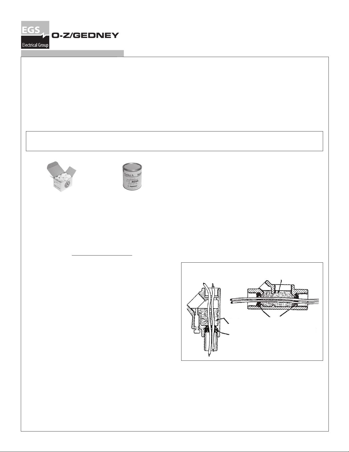
Damming and Pouring:
Sealing Compound
Sealing
Compound
Fiber Filler
Vertical Conduit
Fiber Filler
Horizontal Conduit
Rev. A 09/13/2011
Page 2
CAUTION
Remove any cement from threads in order to allow a minimum of 5 threads engagement of fitting threads, close plug
and drain / breather.
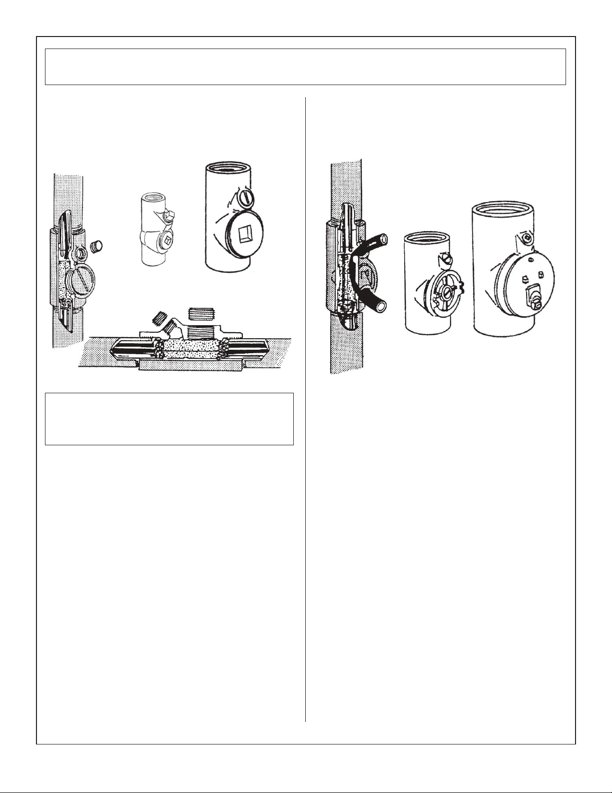
EYAX SEALING SEALING FITTINGS 1/2" TO 4"
EXPLOSION PROOF, DUST-IGNITION-PROOF FOR USE IN: IN
VERTICAL AND / OR HORIZONTAL CONDUIT RUNS
VERTICAL CONDUI
t
EYAX
1/2" - 1"
EYAX
1-1/4" - 4"
HORIZONTAL
CONDUIT
EYDX DRAIN AND SEALING SEALING FITTINGS
CLOSE TURNING RADIUS DRAIN AND SEALING SEALING
FITTINGS, EXPLOSIONPROOF, DUST-IGNITIONPROOF, FOR
USE IN VERTICAL CONDUIT RUNS
EYDX
1" - 2-1/2"
3" - 4"
EYDX
NOTE: On sizes 3", 3-1/2" and 4" the cover should be tightened
down with the small pipe plug removed from it. This will allow
excess cement or air to escape out rather than seeping through or
pushing the dam into the conduit. When the large cover has been
tightened fully, replace pipe plug.
Vertical conduit
1. Install sealing fitting and pull conductors through.
2. Remove the pipe plug where the cement will be poured through
and the large pipe plug or cover with the small pipe plug for size
3", 3-1/2" and 4" at the center of the sealing fitting.
3. Dam the lower hub with fiber filler. (Page 1, Steps 1 & 2.)
4. Replace the large pipe plug or cover with the small pipe plug
for 3", 3-1/2" and 4" sealing fitting, tighten all threaded joints
securely.
5. Mix Sealing Cement with the correct proportion of water per
instructions provided with the cement. (Page 1, Step 3).
6. Pour Sealing Cement mixture into the small pipe plug opening
until the cement is level with the last thread of the opening.
7. Replace and tighten small pipe plug.
Horizontal conduit
1. Install sealing fitting and pull conductors through.
2. Remove all pipe plugs and / or cover from the sealing fitting.
3. Dam both hubs with fiber filler. (Page 1, Steps 1 & 2)
4. Mix Sealing Cement with the correct proportion of water per
instructions provided with the cement. (Page 1, Step 3.)
5. Pour Sealing Cement mixture into the sealing fitting through the
large opening until 2-3 threads are covered with the cement. Fill
hole must be oriented in the upright position.
6. Replace and tighten in sequence the large pipe plug or cover,
the small pipe plug into the sealing fitting and the small pipe
plug into the cover.
1. Install sealing fitting and pull conductors through.
EYDX Series 1" TO 4"
2. Remove the large threaded cover from the sealing fitting.
3. Dam the lower hub opening with fiber filler. (Page 1, Step 2).
4. Replace the large threaded cover so that the threaded hole is
facing downward.
5. Insert the tube and wire drain core into the opening of the large
threaded cover so that the end being inserted will be above the
compound in a completed seal. (See illustration on this page).
6. Be sure that the tube and wire drain core do not touch any of the
conductors, Otherwise, this will expose the conductors in the
completed and hardened seal. (See illustration on this page).
7. Mix Sealing Cement with the correct proportion of water per
instructions provided with the cement. (Page 1, Step 3).
8. Pour Sealing Cement mixture into the sealing fitting through the
opening located above the large cover until the last thread is
covered with cement.
9. After cement has cured, (see page 1, "Caution: For temperature/
cure time") pull out the old tube and wire drain core and discard.
10. Thread the small pipe plug into this opening and tighten .
11. Thread ECDB drain-breather fitting into large cover threaded
hole and tighten securely.
Page 2 502884-1 Rev. A 09/13/2011
Page 3

CAUTION
Remove any cement from threads in order to allow a minimum of 5 threads engagement of fitting threads, close plug
and drain / breather.
FIVE
THREADS
ENGAGEMENT
WASHER
(PROVIDED)
DRAIN
HOLE CORE
EXPLOSION PROOF, DUST IGNITION PROOF FOR USE IN VERTICAL CONDUIT RUNS
EYDX DRAIN AND SEALING SEALING FITTINGS
FIVE THREADS
CONDUCTORS
SHOULD NOT
TOUCH EACH
OTHER
SEALING
COMPOUND
MINERAL FIBER
ASBESTOS FREE
FILLER DAM
MINERAL FIBER
ASBESTOS FREE
FILLER DAM
ECDB
EXPLOSIONPROOF
DRAIN PLUG
ENGAGEMENT
SEALING
COMPOUND
ECDB Explosion-Proof Drain\Breather Application
Drain/breather installed in bottom of housing
to drain water formed by condensation within
system.Drain must be vertical and pointing down
when installed.
EYDX Fitting with a ECDB
Explosion-Proof Drain application
EYDX Series 1/2" and 3/4"
1. Install sealing fitting and pull conductors through.
2. Remove the pipe plug.
3. Dam the lower hub opening with fiber filler. (See page 1, steps 1 and 2)
4. Insert rubber drain-hole core through drain opening and washer (provided) high enough so inner end of core will be above sealing compound
in completed seal.
Note: Washer (provided) must be inserted to last thread to form dam for sealing compound. (See illustration above).
5. Be sure that the rubber drain - hole - core does not touch any of the conductors.
6. Mix Sealing Cement with the correct proportion of water per instructions provided with the cement (Page 1, Step 3.).
7. Pour Sealing Cement mixture into the sealing fitting opening until the cement is level with the last thread of the opening.
8. Replace and tighten pipe plug.
9. When cement has cured (see page 1, Caution: Temperature / cure time") remove drain - hole - core.
10. Thread ECDB drain - breather fitting into threaded hole and tighten securely.
502884-1 Rev. A 09/13/2011 Page 3
Page 4

3 No. 10 THWN cross sectional area = 3.0 x 0.0184 = 0.0552
5 No. 12 THW cross sectional area = 5.0 x 0.0172 = 0.0860
Illustration No. 1 (Wires or conductors of different sizes and types). ‡
Determine required conduit size sealing fitting based on this maximum 40% fill ruling for: 3 No. 10
THWN, 5 No. 12 THW and 5 No. 250 kcmil XHHW conductors.
5 No. 250 kcmil XHHW cross sectional area = 5.0 x 0.4026 = 2.0130
Solution:
Total area occupied by conductors = 2.1542
Hence 40% maximum conductor fill for 3" size sealing fitting = 2.95 sq. inches (meets this requirement).
Class I, Groups B, C & D ‡ Class I, Groups C & D
No. 12 THHN cross sectional area = 0.0117
Illustration No. 1 (Wires or conductors of the same sizes and types). ‡
Determine required conduit size sealing fitting based on this maximum 40%
Total conductor area = 16 x 0.0117 = 0.1872
fill ruling for: 16 No. 12 THHN conductors.
Solution:
Hence 40% maximum conductor fill for 3/4" size sealing fitting = 0.21 sq.
inches (meets this requirement).
2 3 4 5 6 7 9 11 12 14 15 18
TABLE 1: MAXIMUM NUMBER OF CONDUCTORS THAT CAN BE SEALED IN A SEALING FITTING, O-Z/GEDNEY CATALOG NUMBER SERIES EYAX AND EYDX
1/2” Seal 3/4” Seal 1” Seal 1-1/4” Seal 1-1/2” Seal 2” Seal 2-1/2” Seal 3” Seal 3-1/2” Seal 4” Seal
Max. % Fill = 40% Max. % Fill = 40% Max. % Fill = 40% Max. % Fill = 40% Max. % Fill = 40% Max. % Fill = 40% Max. % Fill = 40% Max. % Fill = 40% Max. % Fill = 40% Max. % Fill = 40%
X-Sect. Area = .12 † X-Sect. Area = .21 † X-Sect. Area = .34 † X-Sect. Area = .60 † X-Sect. Area = .82 † X-Sect. Area = 1.34 † X-Sect. Area = 1.92 † X-Sect. Area = 2.95 † X-Sect. Area = 3.96 † X-Sect. Area = 5.00 †
Size
AWG or
A B A B A B A B A B A B A B A B A B A B
Kcmil
18 13 19 24 34 39 55 68 97 92 131 152 217 217 309
16 11 15 19 27 31 43 55 76 75 103 123 170 176 242
14 6 14 10 24 16 39 29 69 39 94 65 154 93 220 143 192
12 5 10 8 18 13 29 24 51 32 69 53 115 76 164 117 157
A Only)
the NEC Dimensions of insulated Conductors and Fixture Wires)
to or greater than calculated total area occupied by conductors versus total
maximum percentage fill area allowed by each corresponding size sealing
Steps to determine size of sealing fitting to use based on 40% fill ruling:
fitting. (See table below for values)
1. Determine cross sectional areas of conductors. (Refer. Chapter 9, Table 5 of
2. Determine total area occupied by conductors.
3. Determine required conduit size sealing fittings based upon a value equal
Wire Types (Column
RHW and RHH
TW, THW, RHW, RHH
8 2 3 3 5 6 9 10 16 13 22 22 36 32 51 49 79 66 106 85 136
10 4 6 7 11 11 18 19 32 26 44 43 73 61 104 95 160 127 163
14 9 14 15 24 25 39 44 69 60 94 99 154 142 220
(without outer
covering), THW
12 7 10 12 18 20 29 35 51 47 69 78 115 111 164 171
TW, XHHW (AWG
10 5 6 9 11 15 18 27 32 37 44 60 73 86 104 133 160 178
14-6)
8 2 3 4 5 7 9 12 16 17 22 28 36 40 51 62 79 84 106 108 136
6 1 2 2 4 4 6 7 11 10 15 16 26 23 37 36 57 48 76 62 98
4 1 1 2 2 3 4 5 7 7 9 12 16 17 22 27 35 36 47 47 60
3 1 1 1 2 2 3 5 6 6 8 10 13 15 19 23 29 31 40 40 51
2 1 1 1 2 2 3 4 5 5 7 9 11 13 16 20 25 27 33 34 43
1 1 1 1 1 2 3 4 4 5 6 8 9 12 14 18 19 25 25 32
1/0 1 1 1 2 2 3 3 4 5 7 8 10 12 15 16 21 21 27
4/0 1 1 1 2 2 2 3 4 5 6 7 9 10 12 13 15
2/0 1 1 1 1 2 2 3 3 5 6 7 8 10 13 14 17 18 22
3/0 1 1 1 2 2
250 1 1 1 1 2 3 3 4 5 6 7 8 10 10 12
300 1 1 1 1 2 3 3 4 5 6 7 8 9 10
350 1 1 1 1 2 2 3 3 4 5 6 7 8 9
400 1 1 1 2 2 2 3 4 5 5 6 7 8
500 1 1 1 2 2 2 3 4 5 5 6 7
600 1 1 1 1 2 2 3 3 4 4 5 5
700 1 1 1 1 2 2 3 3 4 4 5
750 1 1 1 1 2 2 3 3 3 4 4
800 1 1 1 1 2 2 3 3 4 4
900 1 1 1 1 2 2 3 3 3 4
1000 1 1 1 1 2 2 2 3 3 3
1250 1 1 2 2
1500 1 1 2
1750 1 1 2
2000 1 1 1
covering)
thru 2), RHW and
TW, THW, FEPB (6
RHH (without outer
Column B = FEP, THHN, THWN, TFN, PF, PGF, XHHW (AWG4-2000 MCM), FEPB (AWG 14-9)
† Maximum usable conduit cross section area as specified. (Example: For 3 conduit seal 100%) cross sectional area = 7.38 sq. inches. therefor from above maximum fill, i.e., 40% x 7.38 = 2.95 sq inches).
‡ Aluminum EYAX-AL and EYDX-AL Sizes 1-1/2" thru 3-1/2" are UL Listed for Class I, Groups C,D; CSA Certified for Class I, Groups B,C,D
 Loading...