

Appleton Instructions: PlexPower Factory Sealed Contactor and Motor Starter, 504148 | Appleton Manuals & Guides

504148 INSTRUCTION SHEET
Appleton™ PlexPower™ Factory-Sealed Contactor and Motor Starter
Installation and Operation Instructions
FOR PROPER AND SAFE INSTALLATION OF THIS PRODUCT, PLEASE READ THE FOLLOWING INSTRUCTIONS
Signal Words Defined
DANGER indicates a hazardous situation which, if not avoided, will result in death or serious injury. WARNING indicates a hazardous
situation which, if not avoided, could result in death or serious injury. CAUTION indicates a hazardous situation which, if not avoided,
could result in minor or moderate injury. NOTICE is used to address practices not related to physical injury.
Product Safety
The PlexPower™ Contactor and Motor Starter with or without a main breaker is rated 125 amps maximum. For individual breaker
disconnect, maximum rating applies at 30 amps. Contactor and overload relay are rated up to 27 amps, 600 volts AC maximum.
Safety Instructions
WARNING: Ensure that the power to the panel mains is switched off before replacing any parts or accessories in the contactor
and motor starter.
CAUTION: Only authorized personnel may open the unit because live components are installed behind the cover.
NOTICE: To ensure nger-safe operation, a dead pan is supplied inside the unit.
Applications
The Appleton™ PlexPower™ Contactor and Motor Starter provides
electrical protection and control of electrical circuits in hazardous
environments such as:
• Petroleum plants
• Chemical plants
• Reneries
• Wastewater treatment plants
• Paper and pulp industry facilities
• Other process facilities
Appleton • 1.800.621.1506 • www.appletonelec.com 504148 Rev. 04 10/07/19 • Page 1 of 22

Installation
Multiple S1 Motor Starter Panel (Combination)
Single Contactor and Motor Starter - Approximate Weight: 70 kg
15.16
[385]
MTG.
29.5285
[750]
11.5157
[292.5]
MTG.
11.5157
[292.5]
MTG.
13.78
[350]
7.88
[200]
FRONT VIEW
SIDE VIEW
Multiple Contactor and Motor Starter - Approximate Weight: 225 kg
40.75
[1035]
39.37
[1000]
26.28
[667.5]
59.06
[1500]
26.28
[667.5]
9.85
[250]
INTERNAL VIEW
FRONT VIEW
SIDE VIEW
INTERNAL VIEW
504148 Rev. 04 10/07/19 • Page 2 of 22Appleton • 1.800.621.1506 • www.appletonelec.com

Owner’s Responsibilities
• Ensuring that all installation instructions are followed.
• Carefully reading, understanding and following the current edition of the National Electrical Code® (NEC®) or the
Canadian Electrical Code.
• Inspecting the contactor and motor starter thoroughly before operating.
• Understanding how to operate all standard and accessory equipment.
• Ensuring that anyone operating or maintaining the contactor and motor starter is qualied and has been
fully instructed on how to perform those tasks.
• Retaining and storing these instructions for reference during future inspections and maintenance.
Lifting and Transfer
To lift the contactor and motor starter, insert the supplied shackle into the top mounting foot of the enclosure. Lift the unit vertically
with the help of a crane, wire rope, chain, or at lifting belt to enable the movement/transfer to the mounting location.
504148 Rev. 04 10/07/19 • Page 3 of 22Appleton • 1.800.621.1506 • www.appletonelec.com
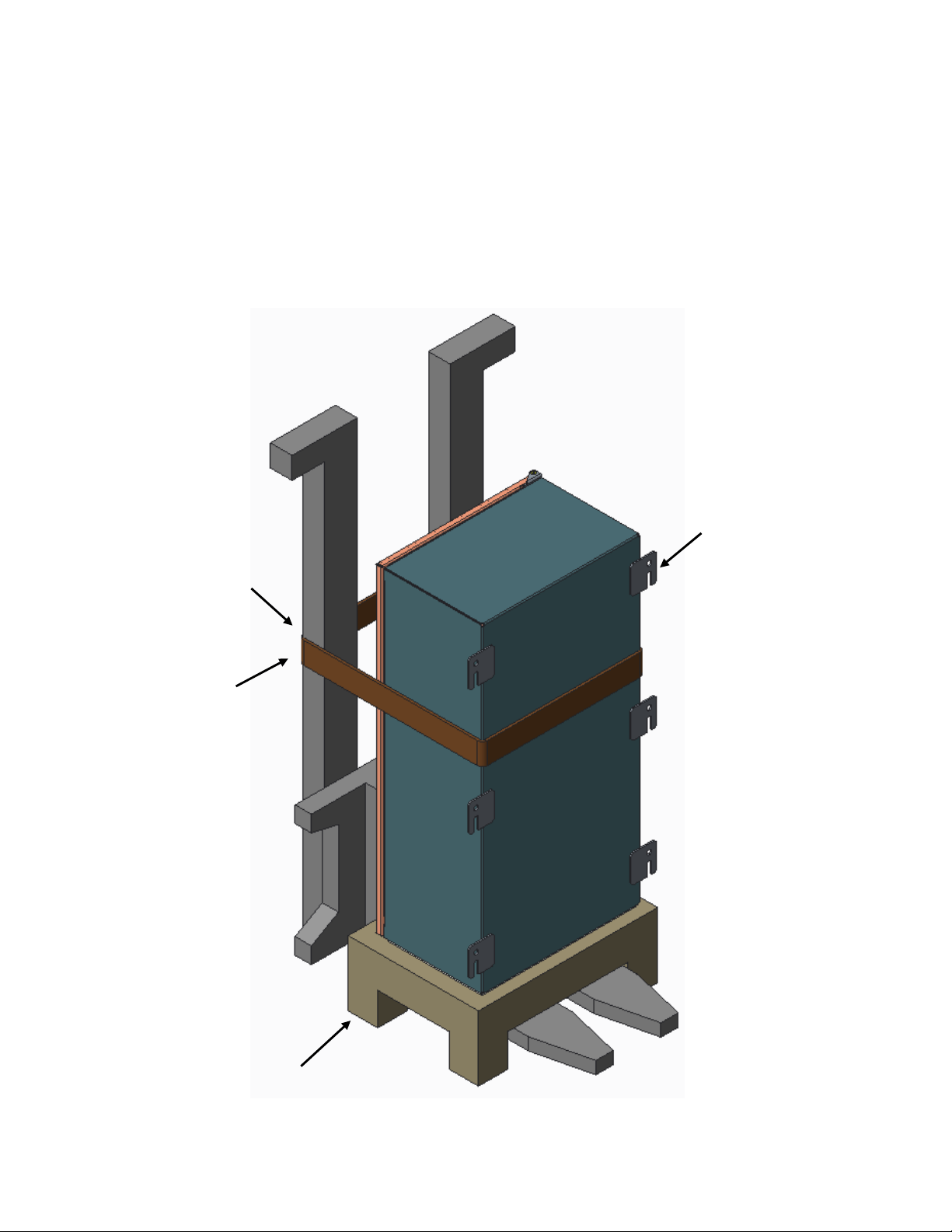
Lifting and Transfer by Forklift Truck:
Anchor Belt for
Additional Safety
Mounting Foot
Pallet
Additional steps need to be taken when transferring the contactor and motor starter from one location to another using a forklift.
1. First, install a pallet or stand onto the forks of the forklift.
2. Then, set the contactor and motor starter vertically onto the pallet or stand.
3. The unit can then be lifted and transferred to the desired location. Moving the unit with a forklift without using a pallet or stand
could damage the gland plate on the bottom of the contactor and motor starter.
4. Ensure that contactor and motor starter’s mounting side is facing forward as the unit is set onto the pallet or stand.
5. For additional safety during the transfer using a forklift, it is necessary to secure the unit to the forklift with a belt, wire rope,
or chain.
6. To prevent injuries, ensure that the forklift operator understands all the steps for the transfer before beginning the process.
504148 Rev. 04 10/07/19 • Page 4 of 22Appleton • 1.800.621.1506 • www.appletonelec.com

Before Mounting the Contactor and Motor Starter
Mounting Foot
U-Slot
Contactor and Motor Starter
• Inspect the mounting feet on unit before beginning the installation. Consult the factory immediately if you nd a mounting foot
damaged or missing. All mounting feet must be in perfect condition to install the unit safely and correctly.
• Make sure that the mounting studs/bolts are in place on the mounting frame, mounting strut, or wall according to the dimensions
specied on the drawings in the “Installation” section of this document.
• The contactor and motor starter is intended to be mounted vertically. Use the “U-Slot” on each mounting foot for positioning and
fastening the unit to the mounting frame, mounting strut, or wall.
• All mounting locations must be secured properly to avoid any damage to the unit or injuries to personnel.
504148 Rev. 04 10/07/19 • Page 5 of 22Appleton • 1.800.621.1506 • www.appletonelec.com

Mounting Procedures
• If the unit was moved by using the eye bolt, secure the bottom mounting locations rst.
• Once the bottom mounting locations are securely fastened, release the lifting accessories and fasten the upper mounting locations
to the mounting frame, mounting strut, or wall.
• After the bottom middle mounting feet are fastened to the mounting frame, mounting strut or wall, remove the eye bolt from top
mounting foot and secure it to the mounting frame, mounting strut or wall with an M10 bolt.
• Make sure that all bolts are fully tightened.
• The number of bolts required to mount the panel should be equal to the number of mounting feet on the panel.
• For the Multiple Contactor and Motor Starter:
- Allow 20 inches of clearance to the left of the panel to facilitate the 120˚ swing of the door.
- The maximum clearance between the oor and bottom side of the panel should be one foot to facilitate the easy operation of
switches and handles.
• For the Single Contactor and Motor Starter:
- Allow 8 inches of clearance to the left of panel to the facilitate the 120˚ swing of the door.
- The maximum clearance between the oor and the bottom side of the panel should be 2'3" to facilitate the easy operation of
switches and handles.
504148 Rev. 04 10/07/19 • Page 6 of 22Appleton • 1.800.621.1506 • www.appletonelec.com

Electrical Connections
Bus Bar
Auxiliary
Block
Terminal
Block
Starter-4
F-Frame
Module
Fuse
Starter-1
Starter-2
Starter-3
F-Frame
Module
F-Frame
Module
F-Frame
Module
Heater
Ground Bar
Bus Bar
Fig.1
Auxiliary
Block
Load Side
Terminal Block
Terminal
Block
F-Frame
Module
Fuse
Thermostat
Starter-1
Starter-2
Starter-3
F-Frame
Module
F-Frame
Module
F-Frame
Module
Ground Lug
Heater
Transformer
1. To open the cover for access to wiring, unlock the latch using a screwdriver.
2. Incoming supply can be wired to the line side main of the main breaker. Figures 1 and 2 represent main connection through the
main breaker. Load side connections are hard-wired (customer wiring). A main ground lug is provided for system ground.
Load Side Connections
(Main Breaker)
Main
Main
Breaker
Breaker
Branch
Branch
Breaker
Breaker
OLR
OLR
Electrical
Connecons
Through
Terminal
Terminal
Contactor
Contactor
504148 Rev. 04 10/07/19 • Page 7 of 22Appleton • 1.800.621.1506 • www.appletonelec.com
 Loading...