

Appleton Instructions: PlexPower Factory Sealed Contactor and Motor Starter, 504148 Manuals & Guides
Page 1

504148 INSTRUCTION SHEET
Appleton™ PlexPower™ Factory-Sealed Contactor and Motor Starter
Installation and Operation Instructions
FOR PROPER AND SAFE INSTALLATION OF THIS PRODUCT, PLEASE READ THE FOLLOWING INSTRUCTIONS
Signal Words Defined
DANGER indicates a hazardous situation which, if not avoided, will result in death or serious injury. WARNING indicates a hazardous
situation which, if not avoided, could result in death or serious injury. CAUTION indicates a hazardous situation which, if not avoided,
could result in minor or moderate injury. NOTICE is used to address practices not related to physical injury.
Product Safety
The PlexPower™ Contactor and Motor Starter with or without a main breaker is rated 125 amps maximum. For individual breaker
disconnect, maximum rating applies at 30 amps. Contactor and overload relay are rated up to 27 amps, 600 volts AC maximum.
Safety Instructions
WARNING: Ensure that the power to the panel mains is switched off before replacing any parts or accessories in the contactor
and motor starter.
CAUTION: Only authorized personnel may open the unit because live components are installed behind the cover.
NOTICE: To ensure nger-safe operation, a dead pan is supplied inside the unit.
Applications
The Appleton™ PlexPower™ Contactor and Motor Starter provides
electrical protection and control of electrical circuits in hazardous
environments such as:
• Petroleum plants
• Chemical plants
• Reneries
• Wastewater treatment plants
• Paper and pulp industry facilities
• Other process facilities
Appleton • 1.800.621.1506 • www.appletonelec.com 504148 Rev. 04 10/07/19 • Page 1 of 22
Page 2

Installation
Multiple S1 Motor Starter Panel (Combination)
Single Contactor and Motor Starter - Approximate Weight: 70 kg
15.16
[385]
MTG.
29.5285
[750]
11.5157
[292.5]
MTG.
11.5157
[292.5]
MTG.
13.78
[350]
7.88
[200]
FRONT VIEW
SIDE VIEW
Multiple Contactor and Motor Starter - Approximate Weight: 225 kg
40.75
[1035]
39.37
[1000]
26.28
[667.5]
59.06
[1500]
26.28
[667.5]
9.85
[250]
INTERNAL VIEW
FRONT VIEW
SIDE VIEW
INTERNAL VIEW
504148 Rev. 04 10/07/19 • Page 2 of 22Appleton • 1.800.621.1506 • www.appletonelec.com
Page 3

Owner’s Responsibilities
• Ensuring that all installation instructions are followed.
• Carefully reading, understanding and following the current edition of the National Electrical Code® (NEC®) or the
Canadian Electrical Code.
• Inspecting the contactor and motor starter thoroughly before operating.
• Understanding how to operate all standard and accessory equipment.
• Ensuring that anyone operating or maintaining the contactor and motor starter is qualied and has been
fully instructed on how to perform those tasks.
• Retaining and storing these instructions for reference during future inspections and maintenance.
Lifting and Transfer
To lift the contactor and motor starter, insert the supplied shackle into the top mounting foot of the enclosure. Lift the unit vertically
with the help of a crane, wire rope, chain, or at lifting belt to enable the movement/transfer to the mounting location.
504148 Rev. 04 10/07/19 • Page 3 of 22Appleton • 1.800.621.1506 • www.appletonelec.com
Page 4
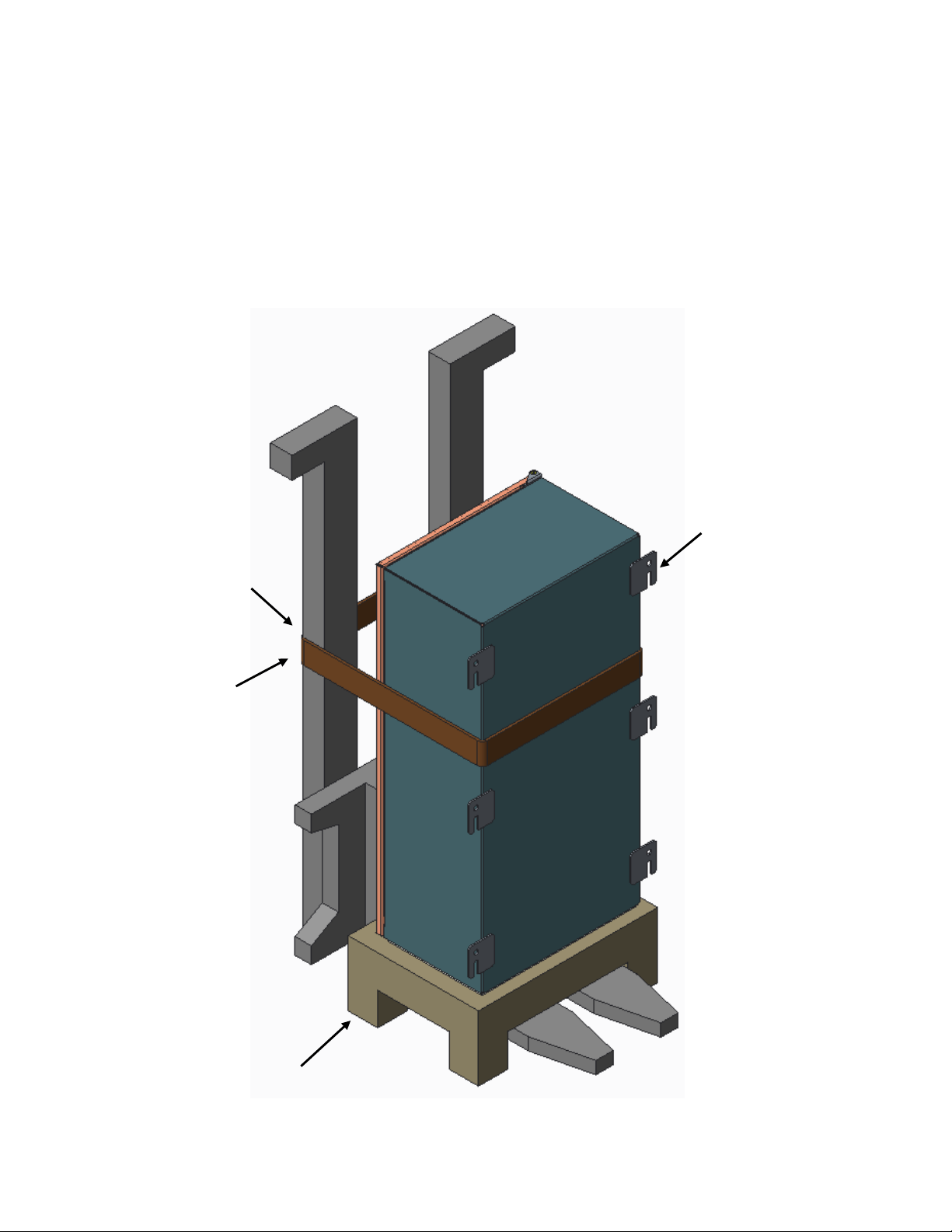
Lifting and Transfer by Forklift Truck:
Anchor Belt for
Additional Safety
Mounting Foot
Pallet
Additional steps need to be taken when transferring the contactor and motor starter from one location to another using a forklift.
1. First, install a pallet or stand onto the forks of the forklift.
2. Then, set the contactor and motor starter vertically onto the pallet or stand.
3. The unit can then be lifted and transferred to the desired location. Moving the unit with a forklift without using a pallet or stand
could damage the gland plate on the bottom of the contactor and motor starter.
4. Ensure that contactor and motor starter’s mounting side is facing forward as the unit is set onto the pallet or stand.
5. For additional safety during the transfer using a forklift, it is necessary to secure the unit to the forklift with a belt, wire rope,
or chain.
6. To prevent injuries, ensure that the forklift operator understands all the steps for the transfer before beginning the process.
504148 Rev. 04 10/07/19 • Page 4 of 22Appleton • 1.800.621.1506 • www.appletonelec.com
Page 5

Before Mounting the Contactor and Motor Starter
Mounting Foot
U-Slot
Contactor and Motor Starter
• Inspect the mounting feet on unit before beginning the installation. Consult the factory immediately if you nd a mounting foot
damaged or missing. All mounting feet must be in perfect condition to install the unit safely and correctly.
• Make sure that the mounting studs/bolts are in place on the mounting frame, mounting strut, or wall according to the dimensions
specied on the drawings in the “Installation” section of this document.
• The contactor and motor starter is intended to be mounted vertically. Use the “U-Slot” on each mounting foot for positioning and
fastening the unit to the mounting frame, mounting strut, or wall.
• All mounting locations must be secured properly to avoid any damage to the unit or injuries to personnel.
504148 Rev. 04 10/07/19 • Page 5 of 22Appleton • 1.800.621.1506 • www.appletonelec.com
Page 6

Mounting Procedures
• If the unit was moved by using the eye bolt, secure the bottom mounting locations rst.
• Once the bottom mounting locations are securely fastened, release the lifting accessories and fasten the upper mounting locations
to the mounting frame, mounting strut, or wall.
• After the bottom middle mounting feet are fastened to the mounting frame, mounting strut or wall, remove the eye bolt from top
mounting foot and secure it to the mounting frame, mounting strut or wall with an M10 bolt.
• Make sure that all bolts are fully tightened.
• The number of bolts required to mount the panel should be equal to the number of mounting feet on the panel.
• For the Multiple Contactor and Motor Starter:
- Allow 20 inches of clearance to the left of the panel to facilitate the 120˚ swing of the door.
- The maximum clearance between the oor and bottom side of the panel should be one foot to facilitate the easy operation of
switches and handles.
• For the Single Contactor and Motor Starter:
- Allow 8 inches of clearance to the left of panel to the facilitate the 120˚ swing of the door.
- The maximum clearance between the oor and the bottom side of the panel should be 2'3" to facilitate the easy operation of
switches and handles.
504148 Rev. 04 10/07/19 • Page 6 of 22Appleton • 1.800.621.1506 • www.appletonelec.com
Page 7

Electrical Connections
Bus Bar
Auxiliary
Block
Terminal
Block
Starter-4
F-Frame
Module
Fuse
Starter-1
Starter-2
Starter-3
F-Frame
Module
F-Frame
Module
F-Frame
Module
Heater
Ground Bar
Bus Bar
Fig.1
Auxiliary
Block
Load Side
Terminal Block
Terminal
Block
F-Frame
Module
Fuse
Thermostat
Starter-1
Starter-2
Starter-3
F-Frame
Module
F-Frame
Module
F-Frame
Module
Ground Lug
Heater
Transformer
1. To open the cover for access to wiring, unlock the latch using a screwdriver.
2. Incoming supply can be wired to the line side main of the main breaker. Figures 1 and 2 represent main connection through the
main breaker. Load side connections are hard-wired (customer wiring). A main ground lug is provided for system ground.
Load Side Connections
(Main Breaker)
Main
Main
Breaker
Breaker
Branch
Branch
Breaker
Breaker
OLR
OLR
Electrical
Connecons
Through
Terminal
Terminal
Contactor
Contactor
504148 Rev. 04 10/07/19 • Page 7 of 22Appleton • 1.800.621.1506 • www.appletonelec.com
Page 8

Electrical Connections (Continued)
Ground
Bar
Heater
Line Side Electrical Connections (MAIN BREAKER)
Ground Lug
F-Frame
Module
F-Frame
Module
F-Frame
Module
Fuses
Transformer
Thermostat
Load Side Electrical Connections
Fig.2
Control
Blocks
Terminal
Main Breaker
Contactor
Overload Relay
504148 Rev. 04 10/07/19 • Page 8 of 22Appleton • 1.800.621.1506 • www.appletonelec.com
Page 9

Wiring Connections for Customer Input and Output
Incoming and outgoing connection to panel:
• To facilitate wiring connection to both the line side and load side of the panel, two holes need to be drilled on the gland plate
provided on the bottom side of enclosure.
- Make sure to utilize the correct and required wire size according to the panel specications.
504148 Rev. 04 10/07/19 • Page 9 of 22Appleton • 1.800.621.1506 • www.appletonelec.com
Page 10

Wiring Diagram
4.2 Wiring Diagram
4.2 Wiring Diagram
To connect wires from load side to the terminal blocks, refer to the wiring diagram below. Also note the terminal block markings.
To connect wires to control terminals for the auxiliary block, refer to the wiring diagram below and to the terminal block markings.
Note: The following directions must be followed for wiring routing through the contactor and motor starter enclosure.
• All wires must be routed in such a way that they will not interfere with each other.
• All wires should be tied with cable ties.
• All wires must be appropriately tagged for easy identication.
• Secure wires rmly by applying the required torque on the pressure screw.
• Special care needs to be taken while connecting wires to line side and load side. Wires routed close to the heater
must be examined carefully as well.
504148 Rev. 04 10/07/19 • Page 10 of 22Appleton • 1.800.621.1506 • www.appletonelec.com
Page 11

Wire Information as per Ampacity
Current (amps) Required Wire Size
15 or less 10 AWG minimum
20–25 8 AWG minimum
30 6 AWG minimum
40–50 4 AWG minimum
60–70 3 AWG minimum
80 2 AWG minimum
90 1 AWG minimum
100 1/0 AWG minimum
110 2/0 AWG minimum
125 3/0 AWG minimum
Terminals - Connection Devices
Purpose
Line Phase 1, 2, 3 6 AWG 1/2" 30 35 in-lbs.
Auxiliary Terminal Blocks 14 AWG 3/8" 10 10 in-lbs.
Control Terminal Blocks 14 AWG 3/8" 10 10 in-lbs.
Power Terminal Blocks 6 AWG 1/2" 30 10 in-lbs.
Ground Lug 4/0 AWG 7/8" 150 150 in-lbs.
Ground Lug 2/0 AWG 7/8" 110 150 in-lbs.
Conductor Size
(UL/CSA)
Conductor Strip Length Maximum Amps Pressure Screw Torque
Electrical Testing
WARNING: All wiring must be checked and tested to ensure all circuits are wired correctly and there are no unwanted opens,
shorts or grounds. Do not apply power until the following steps are completed:
• Test each circuit to verify correct phasing and ground connections.
• Test each circuit for insulation resistance by hi-pot test; to be sure the system does not have any short circuits
or unwanted grounds.
• All wiring completed at the factory will have passed a hi-pot test.
• If any circuit displays a resistance to another circuit or to ground of 1 megaohm or less, that circuit must be analyzed, corrected
and tested to be good to more than 1 megaohm before applying power.
• Perform these tests with the circuit breakers in both the “ON” and “OFF” positions.
• Check the terminals and connectors for looseness or signs of overheating.
• Overheating will show as discoloration, melting, or blistering of conductor/connector insulation, or as pitting or melting of
conductor surfaces due to arcing.
• If there is evidence of overheating, terminations should be cleaned or replaced.
• Before re-energizing the contactor and motor starter, all terminations and cable should be refurbished to the condition
of the original install.
504148 Rev. 04 10/07/19 • Page 11 of 22Appleton • 1.800.621.1506 • www.appletonelec.com
Page 12

Operation
Main Breaker
The status of the breaker is determined by the position of the knob indicated on the label. Operation simply consists of twisting
the handle to the desired position.
Contactor
The status of the contactor is determined by illuminated lights as indicated by the label.
Resetting Tripped Overload Relay
• Simply push the reset button on the panel.
• If it the unit cannot be turned on, it is either not reset, or it is being subjected to conditions which are causing an immediate trip.
Investigate the circuit immediately.
504148 Rev. 04 10/07/19 • Page 12 of 22Appleton • 1.800.621.1506 • www.appletonelec.com
Page 13

Position Selector Switch Operation
Auto Mode
• “Auto” mode allows the user to operate the motor from a remote location. By selecting the “auto” mode, the user does not
need to start and stop the motor locally provided there is an electrical switch connected from Terminal Block 2 (TB2) to Terminal
Block 4 (TB4) as depicted in the diagram below.
Hand Mode
• “Hand” mode enables the user to start and stop the motor manually.
Off Mode
• When the “Off” mode is selected, the user cannot start the motor remotely or manually.
504148 Rev. 04 10/07/19 • Page 13 of 22Appleton • 1.800.621.1506 • www.appletonelec.com
Page 14

General Maintenance
WARNING: Electrical power must be disconnected before and during maintenance. Modication of this contactor and motor
starter or substitution of parts with non-standard parts may result in serious/fatal injury.
Maintenance
• Before carrying out any work on equipment, cited safety instructions must be very carefully observed.
1. Disconnect power to the contactor and motor starter panel before opening the panel.
2. The main breaker and branch breaker should be locked and tagged out for safety during maintenance procedures.
3. The hardware installed shall be inspected on regular schedule.
4. It is the user’s responsibility to ensure these inspections are implemented according to the protection modes of the equipment
hardware installed.
5. Before use of the contactor and motor starter, check that all module cover attaching screws are properly tightened to ensure that
the product remains explosion-proof.
6. The ameproof function for product must be kept for complete duration of service life therefore joints must be maintained
in good condition.
• No scratches, marks or modications are allowed on parts such as the module body and module cover which are critical
for amepath integrity.
• To ensure the security and electrical safety of the unit, the external lug assembly and connecting wires from other devices should
be checked on a regular basis
• Any appliance found to be defective should be replaced as quickly as possible.
• Perform visual, electrical, and mechanical checks on all components on a regular basis.
• Visually check for undue heating as evidenced by discoloration of wires or other components, damaged or worn parts, or leakage
as evidenced by water or corrosion of the interior.
• Electrically check to ensure that all connections are clean and tight.
• Mechanically check that all parts are properly assembled, and operating mechanisms move freely.
• Contact Appleton if the contactor and motor starter does not function correctly.
• Maintenance should be done only by skilled and authorized personnel who have complete knowledge and understanding of the
product, its applications, and requirements.
504148 Rev. 04 10/07/19 • Page 14 of 22Appleton • 1.800.621.1506 • www.appletonelec.com
Page 15

Module Assembly General Maintenance
**Important: No modification allowed to these areas.
IMPORTANT: No scratch marks or modications are allowed on parts or features which are critical for amepath integrity.
In general, no scratches/marks/modication are allowed on the body ange and cover ange areas. Damage to these parts/features
may compromise the ameproof function of entire housing.
Alignment of Mistake-proof Feature
While assembling the body and cover, ensure the alignment of the mistake-proof feature orientation on the body and cover. Also
check for correct orientation and placement of the cover to avoid any damage.
504148 Rev. 04 10/07/19 • Page 15 of 22Appleton • 1.800.621.1506 • www.appletonelec.com
Page 16

Replacement Of F-Frame Main/Branch Breaker
Replacement of Contactor: Replacement of Overload Relay:
Replacement of Contactor: Replacement of Overload Relay:
Replacement of Contactor: Replacement of Overload Relay:
Replacement of Contactor: Replacement of Overload Relay:
Replacement of Contactor: Replacement of Overload Relay:
Replacement of Contactor: Replacement of Overload Relay:
1. Remove F-Frame cover from body by unscrewing M8 screws.
2. Once the cover is off, unscrew the #10-32 screws from the body, The main/branch breaker can now be uninstalled
from the body.
3. Install new breaker into the body. While installing the breaker into the body, make sure that it is installed with the correct orientation
(line side/load side).
4. After installing the breaker, secure it with the #10-32 screws to a torque value of 35 in-lbs.
5. After installing the breaker into the body, check the mistake-proof feature orientation, then replace the cover. Fasten the M8 screws
to a torque value of 90 in-lbs.
1. REMOVE COVER.
4. SECURE MAIN/BRANCH
BREAKER WITH SCREWS.
2. UNINSTALL MAIN/BRANCH
BREAKER FROM BODY.
5. REPLACE COVER AND
FASTEN WITH M8 SCREWS.
3. INSTALL NEW MAIN/BRANCH
BREAKER INTO BODY.
CLOSE-UP VIEW OF ASSEMBLED
F-FRAME MAIN/BRANCH BREAKER.
504148 Rev. 04 10/07/19 • Page 16 of 22Appleton • 1.800.621.1506 • www.appletonelec.com
Page 17

Replacement of Contactor
Replacement of Contactor: Replacement of Overload Relay:
1. Remove the F-Frame cover from the body by unscrewing the M8 screws.
2. Once the cover is removed, unscrew power and control connection from the contactor and auxiliary, respectively. Then,
remove contactor from DIN rail.
3. Install the new contactor into the body. While installing the new contactor into the body, make sure that it is installed with the
correct orientation (line side/load side).
4. After installing the contactor into its designated place, make all power and control connections.
5. After installing the contactor into the body, check the mistake-proof feature orientation, then replace the cover. Fasten the M8
screws to a torque value of 90 in-lbs.
1. REMOVE COVER.
2. UNINSTALL CONTACTOR
FROM DIN RAIL.
3. INSTALL NEW CONTACTOR
ONTO DIN RAIL.
CLOSE-UP VIEW AFTER
CONTACTOR REPLACEMENT.
4. MAKE ALL POWER AND
CONTROL CONNECTIONS.
5. REPLACE COVER AND
FASTEN WITH M8 SCREWS.
504148 Rev. 04 10/07/19 • Page 17 of 22Appleton • 1.800.621.1506 • www.appletonelec.com
Page 18

Replacement of Overload Relay
1. Remove the F-Frame cover from the body by unscrewing the M8 screws.
2. Once the cover is removed, unscrew the power and control connection from the overload relay and auxiliary switch. Then,
remove the overload relay with its stand from the DIN rail.
3. Push the new overload relay into the stand and install overload relay with stand into the body. While installing the overload relay
into the body, make sure that it is installed with the correct orientation (line side/load side).
4. After installing the overload relay into its designated place, make all power and control connections.
5. After installing the overload relay into the body, check the mistake-proof feature orientation, then replace the cover. Fasten the M8
screws to a torque value of 90 in-lbs. NOTE: If the overload relay is damaged, order a new relay with mounting stand.
1. REMOVE COVER.
4. MAKE ALL POWER AND
CONTROL CONNECTIONS.
2. UNINSTALL OVERLOAD RELAY
FROM DIN RAIL.
5. REPLACE COVER AND
FASTEN WITH M8 SCREWS.
3. INSTALL NEW OVERLOAD
RELAY ONTO DIN RAIL.
CLOSE-UP VIEW AFTER
OVERLOAD RELAY REPLACEMENT.
504148 Rev. 04 10/07/19 • Page 18 of 22Appleton • 1.800.621.1506 • www.appletonelec.com
Page 19

Wiring Connection for Contactor and Line Bushing Installed in Housing
After installing the new contactor into the housing, make line bushing connections on the contactor as shown in the diagram below.
Once the connections are completed, verify that all wires are secured into their correct locations as per the wiring diagram. Pay careful
attention to the markings on contactor terminals and on line bushing wires.
Wiring Connection for Overload Relay and Line Bushing Installed in Housing
After installing the new overload relay into the housing, make line bushing connections on the overload relay as shown in the diagram
below. Once the connections are completed, verify that all wires are secured into their correct locations as per the wiring diagram. Pay
careful attention to the markings on overload relay terminals and on line bushing wires.
504148 Rev. 04 10/07/19 • Page 19 of 22Appleton • 1.800.621.1506 • www.appletonelec.com
Page 20

Replacement of Fuses
1. Unscrew Cap
2. Extract Fuse
from Fuse Holder
3. Install New Fuse
into Fuse Holder
4. Replace Cap
5. Final Assembly
After Replacement of Fuse
• Check the continuity of the fuse. If it is broken, replace fuse from the fuse holder.
1. Unscrew the FU40 fuse holder cap.
2. Remove the fuse from the fuse holder body.
3. Install a new fuse into the fuse holder.
4. Replace cap by screwing onto the body until it is securely fastened hand-tight.
504148 Rev. 04 10/07/19 • Page 20 of 22Appleton • 1.800.621.1506 • www.appletonelec.com
Page 21

Replacement Parts
Description Quantity Catalog No.
Illuminated PB - Red 1 59550745000
Illuminated PB - Green 1 59550746000
Push Button - Start 1 UA0GP
Push Button - Stop UA0RP
Push Button - Reset 1 59550751000
Pilot Light - Red 1 UPR0P
Pilot Light - Green 1 UPG0P
Pilot Light - Yellow 1 UPY0P
Selector Switch - 3 position 1 59550747000
Heater ON LED light 1 59351106000
Push Button Insert - Black 2 UIAN
Illuminated Push Button Insert - Red 1 UILR
Illuminated Push Button Insert - Green 1 UILG
Hand - Off - Auto Legend Plate 1 ULPSJ04
Run Legend Plate 1 ULPSA06
Start Legend Plate 1 ULPSA07
Stop Legend Plate 1 ULPSA08
Reset Legend Plate 1 ULPSA20
Heater Legend Plate 1 ZF8603
Quarter turn latch - Padlockable 1 59303581000
Quarter turn latch - Slotted Head 1 59303512000
Gland Plates
Gland Plate for enclosure M1 and W1 1 JBESGP3720
Gland Plate Gasket for enclosure M1 and W1 1 JBESGP3720GKT
Gland Plate Hardware for enclosure M1 and W1 1 JBESGP3720HDW
Gland Plate for enclosure N1 and R1 1 JBESGP3520
Gland Plate Gasket for enclosure N1 and R1 1 JBESGP3520GKT
Gland Plate Hardware for enclosure N1 and R1 1 JBESGP3520HDW
Gland Plate for enclosure T1 1 JBESGP4520
Gland Plate Gasket for enclosure T1 1 JBESGP4520GKT
Gland Plate Hardware for enclosure T1 1 JBESGP4520HDW
Gland Plate for enclosure I1, E1, and G1 1 JBESGP7525
Gland Plate Gasket for enclosure I1, E1, and G1 1 JBESGP7525GKT
Gland Plate Hardware for enclosure I1, E1, and G1 1 JBESGP7525HDW
Gland Plate for enclosure Q1 and P1 1 JBESGP1025
Gland Plate Gasket for enclosure Q1 and P1 1 JBESGP1025GKT
Gland Plate Hardware for enclosure Q1 and P1 1 JBESGP1025HDW
504148 Rev. 04 10/07/19 • Page 21 of 22Appleton • 1.800.621.1506 • www.appletonelec.com
Page 22

Description Quantity Catalog No.
Heater - HEF 50W 1 59550866000
Heater - MicroTherm 75W 1 59550838001
Heater - MultiTherm 100W 1 59503930000
Thermostat 1 59503931000
Transformer - 50VA 1 E050JN
Transformer - 100VA 1 E100JN
Transformer - 150VA 1 E150JN
Transformer - 250VA 1 E250JN
Transformer Terminal Cover 1 IP20
Fuses
Fuse Holder 1 FU40
Fuse - 0.5A 1 59503856003
Fuse - 1A 1 59503856002
Fuse - 2A 1 59503856001
Fuse - 4A 1 59503856000
Hardware kit - contains screws, cover bolts, lugs and ground bar RMSHDWKIT
Except as expressly provided by Appleton Grp, LLC (Appleton), Appleton products are intended for ultimate purchase by industrial users and for operation by persons trained and experienced in the use and maintenance of this equipment
and not for consumers or consumer use. Appleton warranties DO NOT extend to, and no reseller is authorized to extend Appleton’s warranties to any consumer.
While every precaution has been taken to ensure accuracy and completeness in this manual, Appleton Grp, LLC. assumes no responsibility, and disclaims all liability for damages resulting from use of this information or for any errors or
omissions. Specications are subject to change without notice. The Appleton and Emerson logos are registered in the U.S. Patent and Trademark Ofce. All other product or service names are the property of their registered owners.
©2019 Appleton Grp, LLC. All rights reserved.
504148 Rev. 04 10/07/19 • Page 22 of 22
 Loading...