

Instruction Sheet: Rigmaster™ LED Series Luminaires, Class I, Division 2 with Emergency Battery Backup, 650610-000 | Appleton
Appleton Instruction Sheet: Rigmaster™ LED Series Luminaires, Class I, Division 2 with Emergency Battery Backup, 650610-000 | Appleton Manuals & Guides

650610-000 INSTRUCTION SHEET
Installation Instructions Appleton™ Rigmaster™ LED Luminaire
with Emergency Battery Backup
FOR PROPER AND SAFE INSTALLATION OF THIS PRODUCT, PLEASE READ THE FOLLOWING INSTRUCTIONS.
Product Safety
Signal Words Defined
DANGER indicates a hazardous situation which, if not avoided, will result in death or serious injury. WARNING indicates a hazardous
situation which, if not avoided, could result in death or serious injury. CAUTION indicates a hazardous situation which, if not avoided,
could result in minor or moderate injury. NOTICE is used to address practices not related to physical injury.
Safety Instructions for Luminaire
WARNING:
• Before installation, ensure that the unit complies with the hazardous area classication. Refer to luminaire nameplate, located on
exterior of housing body, for suitability in specic hazardous locations.
• Do not open or remove the luminaire with the circuit energized.
• Do not remove or replace fuse when luminaire is energized.
• Do not use luminaire on ungrounded systems. Failure to ground this luminaire can result in an electric shock, which may be fatal.
• Do not mount near gas or electric heaters.
• Use two safety cables for installations experiencing high vibrations.
• Do not open when explosive atmospheres are present.
• Supply wires are to be rated for minimum 90°C.
• To reduce the risk of ignition of hazardous atmosphere, disconnect the luminaire from the main supply circuit and wait until the
battery gets de-energized (Minimum 90 minutes for RM********H*** and minimum 180 minutes for RM********E***) before opening the
xture. Keep tightly closed when in operation.
• Make sure to tighten unused close-up plugs after applying TLNC4 grease. TLNC4 grease shall be applied in 3 lines, spaced
approximately 120 degrees apart, perpendicular to the threads.
CAUTION:
• Do not look directly at the LEDs when energized.
• Disconnect the luminaire from the supply circuit before opening to reduce the risk of ignition in hazardous atmospheres.
• Disconnect battery pack through quick disconnect while opening luminaire for servicing.
• Do not attempt to service the battery. The unit uses a sealed, Ni-MH battery which requires no maintenance. For replacement,
contact Customer Service.
• To avoid burning hands, allow luminaire to cool down prior to maintenance.
• Do not replace any component in hazardous area. Move the luminaire into the area known to be non-hazardous.
• Lens cleaning instructions: Wipe/clean from the outside only with a moist cloth. (Beware of electrostatic charges.)
• When installing in a hazardous location, it is necessary that the reector, lens, and all certied conduit plugs be in place and
tightened securely to the housing.
NOTICE:
• Do not touch the LEDs; touching could leave oily deposits, causing hot spots and potential premature failure.
• The LED lens should be cleaned periodically from the outside only with a moist cloth to maintain lighting efciency.
• The use of accessory equipment not recommended by the manufacturer may cause an unsafe condition.
• This luminaire is designed for and should be installed with hazardous locations wiring method required in accordance with the
National Electrical Code®/Canadian Electrical Code and all applicable local codes.
• This product must be installed in accordance with the applicable installation code by a person familiar with the construction and
operation of the product and hazards involved.
• Do not use this equipment for anything other than its intended use.
• This luminaire is provided with a factory installed emergency lighting battery pack.
Appleton • 1.800.621.1506 • www.appletonelec.com 650610-000 Rev. 03 11/02/20 • Page 1 of 43

Applications/Intended Use
• Areas where ammable gases and vapors are present under conditions dened by the ratings below.
• Areas of low clearance, low ceiling heights, or where luminaire weights must be minimized.
• Non-hazardous locations where severe weather conditions, excessive moisture, dirt, dust, corrosive atmospheres, and high
ambient temperatures are encountered.
• Where exible cord is used, it should be approved for extra hard, wet location usage and shall have a separate ground conductor.
• Luminaire is suitable for mounting height as per table-1 to meet 1 Foot-Candle requirement during emergency operation.
Table 1: Suitable Mounting Height
Duration Setting Clear Lens Diffused Lens
90 Minutes <18 ft <16 ft
180 Minutes <14 ft <13 ft
Agency Ratings: (NEC/CEC)
• Class I, Division 2, Groups A, B, C, D • Class I, Zone 2, Group IIC
• Class II, Division 1, Groups E, F, G • Zone 20
• Class III • Wet Locations
• Type 3R, 4 & 4X • Simultaneous Exposure
• IP66
NOTES:
Refer product nameplate, located on the housing body, for details.
650610-000 Rev. 03 11/02/20 • Page 2 of 43Appleton • 1.800.621.1506 • www.appletonelec.com

Dimensions/Details
LUMINAIRE DIMENSIONS
FIGURE 1: RIGMASTER 2 FT. LUMINAIRE WITH EMERGENCY BATTERY BACKUP
FIGURE 2: RIGMASTER 4 FT. LUMINAIRE WITH EMERGENCY BATTERY BACKUP
General Mounting Instructions
1. Make sure power is disconnected before installing the luminaire.
2. Determine appropriate mounting distance between mounting holes for your application.
3. Use bolts (not supplied) appropriate for the structural support member.
4. Secure luminaire to structural support element having through holes that can handle the weight of the luminaire in accordance with
local building code and all other code requirements.
5. Tighten the bolts to secure the luminaire in place.
650610-000 Rev. 03 11/02/20 • Page 3 of 43Appleton • 1.800.621.1506 • www.appletonelec.com

Mounting Brackets
LARGE SWIVEL BRACKET (RMHLSB)
1. Make sure power is disconnected & circuit is de-energized before installing the bracket.
2. Determine appropriate mounting distance between holes on the brackets for your application. Refer to Figure 3(C).
3. Secure RMHLSB bracket to structural support member with appropriate bolts (not supplied) that can handle the weight of luminaire
in accordance with local building code and all other code requirements.
4. Raise luminaire to mounted RMHLSB bracket and secure it using M8 washer and bracket mounting screw (M8 X 18) supplied with
the bracket on both sides.
5. Align the luminaire to the desired aiming position with your free hand and use Locking screw (M8 X 18) supplied with the bracket to
hold at that position. Refer to Figure 3(A).Tighten all the screws to secure the luminaire in place with a torque of 15 N.m (133 Lb.in).
FIGURE 3: MOUNTING BRACKET - RMHLSB BRACKET
650610-000 Rev. 03 11/02/20 • Page 4 of 43Appleton • 1.800.621.1506 • www.appletonelec.com

LOW PROFILE FIXED BRACKET (RMHLPB)
1. Make sure power is disconnected & circuit is de-energized before installing the bracket.
2. Determine appropriate mounting distance between holes on the brackets for your application. Refer to Figure 4(C).
3. Secure RMHLPB bracket to structural support member with appropriate bolts (not supplied) that can handle the weight of luminaire
in accordance with local building code and all other code requirements.
4. Raise luminaire to mounted RMHLPB bracket and secure using M8 washer and bracket mounting screw (M8 X 18) supplied with
the bracket on both sides.
5. Use locking screw (M8 X 18) supplied with the bracket such that they are diagonally opposite to each other on either side. Refer to
Figure 4(C) for hole locations. Make sure bracket is locked to its position.
6. Tighten all the screws to secure the luminaire in place with a torque of 15 N.m (133 Lb.in).
FIGURE 4: MOUNTING OPTIONS - RHMLPB BRACKET
MOUNTING BRACKET COMPATIBILITY CHART FOR RETROFIT INSTALLATIONS
Table 2: Bracket Compatibility with Retrofit Installations
Appleton Part Number
Manufacturer Part Number
Crouse Hinds DP1057MTK X X
LTXW4 X X
Dialight
AZZ™ Rigalite 53050 X X
“X” Denotes compatible with respective Cross reference.
LTXW4LP X X
LSXW4 X X
RMHLSB RMHLPB
Large Swivel Bracket Low Profile Bracket
650610-000 Rev. 03 11/02/20 • Page 5 of 43Appleton • 1.800.621.1506 • www.appletonelec.com

Wiring Options
WARNING: The luminaire must be grounded as required by the National Electrical Code (Paragraph 410.21 and Article 250) or
Canadian Electrical Code (Rule 30-500 and Section 10). Verify that ground continuity has been established by using an Ohm meter or
other suitable testing equipment before energizing the luminaire. Failure to properly ground the luminaire will create an electric shock
hazard, which can cause serious injury or death.
Please use supply wires with temperature rating 90°C or above.
Wiring the Rigmaster™ Emergency Battery Back-up LED Luminaire
For Luminaire with Wire Nut Option
NOTE: Each wire nut can accept 2 # AWG12 (user wires) with 1 # AWG18 wires (Driver wire). Refer to the table below for
power system application.
TABLE 3:
POWER SYSTEM BLACK WHITE GREEN
L-N AC POWER SYSTEM HOT / LINE NEUTRAL GROUND
L-L AC POWER SYSTEM HOT 1 / LINE 1 HOT 2 / LINE 2 GROUND
1. Make sure power is Switched off before wiring the luminaire.
2. A. Wiring with Multi-conductor Cable: Strip the cable outer jacket as required. Strip the insulation of individual wire by
approximately 13 mm (0.5 in)
B. Wiring with Individual Wires: Strip the insulation of individual wire by approximately 13 mm (0.5 in)
3. For standard Wiring:
A. Open the luminaire wiring compartment by loosening the eight captive screws. Allow the cover to swing open, enabling
access to the wiring compartment. See Figure 5. Pull in the luminaire’s supply input wires (by removing wire nuts) through
the cable entry hole, inside the wiring compartment.
B. Pull in the facility electrical supply wires through the same conduit entry hole.
C. Connect electrical power supply leads to wire conductors with the help of wire nuts by holding wires together with even
ends. For Wiring diagram refer to one of the figures from Figure 7A, Figure 7B, Figure 7C, & Figure 7D in conjunction
with section ‘Wiring Methods’ as applicable.
D. Connect the battery by plugging in the quick connector.
E. Check all connections for continuity and ground integrity and close the luminaire wiring compartment cover.
F. Tighten the eight captive screws by applying a torque of 2.25 N.m (20 lbf-in) using the sequence shown as in gure 11.
Make sure wires do not pinch between cover and wiring compartment while closing.
4. For through feed Wiring (for all conduit sizes):
A. Open the luminaire wiring compartment by loosening the eight captive screws on cover. Allow the cover to swing
open, enabling access to the wiring compartment. See Figure 5.
B. Pull in the luminaire’s supply input wires (by removing wire nuts) through the cable entry hole, inside the
wiring compartment.
C. Pull in the facility electrical supply wires from both sides through the conduit entry holes.
D. Connect electrical power supply leads to the respective wires with the help of wire nuts supplied with luminaire by holding
wires together with even ends. For Wiring diagram refer one of the gures from Figure 8A, Figure 8B, Figure 8C, & Figure
8D in conjunction with section ‘Wiring Methods’ as applicable.
E. Connect the battery by plugging in the quick connector.
F Check all connections for continuity and ground integrity and close the luminaire wiring compartment cover.
G. Tighten the eight captive screws by applying a torque of 2.25 N.m (20 Lb.in) using the sequence shown as in Figure 11.
Make sure wires do not pinch between cover and wiring compartment when closing.
5. Apply TLNC4 grease on plugs (3 supplied) in 3 lines, spaced approximately 120 degrees apart, perpendicular to the threads.
After applying TLNC4 grease close all unused conduit entries with plugs. Apply torque of 45 N.m (400 Lb.in.) for 3/4" NPT plug,
28 N.m (250 Lb.in.) for 1/2 “ NPT plug and 25 N.m (225 Lb. in.) for M20 plug.
6. For continuous row mounting below mentioned number of luminaires can be connected.
• Maximum 28 luminaires of 4300 lm connected in series
• Maximum 15 luminaires of 7600 lm connected in series
650610-000 Rev. 03 11/02/20 • Page 6 of 43Appleton • 1.800.621.1506 • www.appletonelec.com

7. Apply AC power to the unit. LED indicator on to the luminaire should begin to ash green. If it ashes red; please refer to the
Troubleshooting/Maintenance section.
8. Battery will be fully charged within 24 hours (maximum). Emergency luminaire may or may not light at this time, depending on
the degree to which battery is charged.
FIGURE 5: RIGMASTER EMERGENCY LUMINAIRE WITH WIRE NUT OPTION
For Luminaire With Fixed Screw Terminal Option
NOTE: See the product nameplate for supply wire requirements. The terminal block can accept 12-22 AWG wire. Use the appropriate
wire gauge based on the application.
TABLE 4:
POWER SYSTEM L N PE
L-N AC POWER SYSTEM HOT / LINE NEUTRAL GROUND
L-L AC POWER SYSTEM HOT 1 / LINE 1 HOT 2 / LINE 2 GROUND
1. Make sure power is disconnected before wiring the luminaire.
2. Open the luminaire wiring compartment by loosening the eight captive screws. Allow the cover to swing open, enabling access
to the wiring compartment. see Figure 6.
A. Wiring with Multi-conductor Cable
1. Strip the cable outer jacket as required.
2. Insert the cable through the conduit entry (with appropriate cable tting attached) to the luminaire
wiring compartment.
B. Wiring with Individual Wires
1. Run conductors down through the conduit to the luminaire wiring compartment.
3. For standard Wiring:
A. Strip the individual wires by approximately 8 mm (0.3 in) and insert them into the proper terminal block connections. The
connection Poles are identied on the Cover as: L’ = Line prime, L = Line, N = Neutral, and E = Ground. Tighten down
the terminal block screws onto the wire with torque of 0.75 N.m (6.5 Lb.in). For Wiring diagram refer to one of the gures
from Figure 9A, Figure 9B, Figure 9C, & Figure 9D that ts best as per application requirement in conjunction with section
‘Wiring Methods’ as applicable.
4. For Through Feed Wiring:
A. Strip the individual wires by approximately 8 mm (0.3 in) and insert them into the proper terminal block connections on
both sides. The connection Poles are identied on the Cover as: L’ = Line prime, L = Line, N = Neutral, and E = Ground.
Tighten down the terminal block screws onto the wire with torque of 0.75 N.m (6.5 Lb.in). For Wiring diagram refer one
of the gures from Figure 10A, Figure 10B, Figure 10C, & Figure 10D that ts best as per application requirement in
conjunction with section ‘Wiring Methods’ as applicable.
5. Connect the battery by plugging in the quick connector.
6. Check all connections for continuity and ground integrity.
7. Once the terminal block is wired to power supply connection, close the luminaire wiring compartment cover.
650610-000 Rev. 03 11/02/20 • Page 7 of 43Appleton • 1.800.621.1506 • www.appletonelec.com

8. Tighten the eight captive screws by applying a torque of 2.25 N.m (20 Lb.in) using the sequence shown as in Figure 11. Make
sure wires do not pinch between cover and wiring compartment while closing.
9. Apply TLNC4 grease on plugs (3 supplied) in 3 lines, spaced approximately 120 degrees apart, perpendicular to the threads.
After applying TLNC4 grease close all unused conduit entries with plugs. Apply torque of 45 N.m (400 Lb.in.) for 3/4” NPT plug,
28 N.m (250 Lb.in.) for 1/2 “ NPT plug and 25 N.m (225 Lb. in.) for M20 plug.
10. For continuous row mounting below mentioned number of luminaires can be connected.
• Maximum 28 luminaires of 4300 lm connected in series.
• Maximum 15 luminaires of 7600 connected in series
11. Apply AC power to the unit. LED indicator on the luminaire should begin to ash green. If it ashes red; please refer to the
Troubleshooting/Maintenance section.
12. Battery will be fully charged within 24 hours (maximum). Emergency luminaire may or may not light at this time, depending on
the degree to which battery is charged.
FIGURE 6: RIGMASTER EMERGENCY LUMINAIRE WITH SCREW TERMINAL OPTION
Wiring Methods
Wiring Method for 4 Wire Connection
1. Connect Direct supply Line to L’ terminal/wire nut. See Figure 7A/7B/8A/8B/9A/9B/10A/10B as applicable.
2. Connect Line coming through AN external Switch to L terminal/wire nut. See Figure 7A/7B/8A/8B/9A/9B/10A/10B as applicable.
3. Connect Neutral & Ground to N terminal/wire nut & E/G terminal/wire nut respectively.
4. Please note both Lines (L and L’) are from same source and are split to enable xture control via a secondary switch for routine
on/off functionality while still keeping battery charged for emergency purposes.
5. Please note that interchanging line connection will result in inappropriate operation and will trigger emergency once supply is
disconnected through switch and will drain battery.
6. It is recommended to connect luminaire using one of the depicted wiring schemes only to ensure proper operation of emergency
luminaire.
Wiring Method for 3 Wire Connection
1. For wire nut option Connect Line wires to L wire & L’ wire into one wire nut (refer g 7C/7D or g 8C/8D)
2. For xed terminal option short L Wire & L’ wire with in xture with a connector (refer g 9C/9D or g 10C/10D).
3. Connect Neutral & Ground to N terminal/wire nut & E/G terminal respectively.
4. Please note that in this wiring scheme luminaire should be powered continuously to keep battery charged, absence of power
supply will trigger Emergency mode.
650610-000 Rev. 03 11/02/20 • Page 8 of 43Appleton • 1.800.621.1506 • www.appletonelec.com

Wiring Diagrams
FIGURE 7A: STANDARD WIRING 4 WIRE CONNECTION LAYOUT WITH WIRE NUTS: 2FT
FIGURE 7B: STANDARD WIRING 4 WIRE CONNECTION LAYOUT WITH WIRE NUTS: 4FT
650610-000 Rev. 03 11/02/20 • Page 9 of 43Appleton • 1.800.621.1506 • www.appletonelec.com

FIGURE 7C: STANDARD WIRING 3 WIRE CONNECTION LAYOUT WITH WIRE NUTS: 2FT
FIGURE 7D: STANDARD WIRING 3 WIRE CONNECTION LAYOUT WITH WIRE NUTS: 4FT
650610-000 Rev. 03 11/02/20 • Page 10 of 43Appleton • 1.800.621.1506 • www.appletonelec.com

FIGURE 8A: THROUGH FEED WIRING 4 WIRE CONNECTION LAYOUT WITH WIRE NUTS: 2FT
FIGURE 8B: THROUGH FEED WIRING 4 WIRE CONNECTION LAYOUT WITH WIRE NUTS: 4FT
650610-000 Rev. 03 11/02/20 • Page 11 of 43Appleton • 1.800.621.1506 • www.appletonelec.com

FIGURE 8C: THROUGH FEED WIRING 3 WIRE CONNECTION LAYOUT WITH WIRE NUTS: 2FT
FIGURE 8D: THROUGH FEED WIRING 3 WIRE CONNECTION LAYOUT WITH WIRE NUTS: 4FT
650610-000 Rev. 03 11/02/20 • Page 12 of 43Appleton • 1.800.621.1506 • www.appletonelec.com
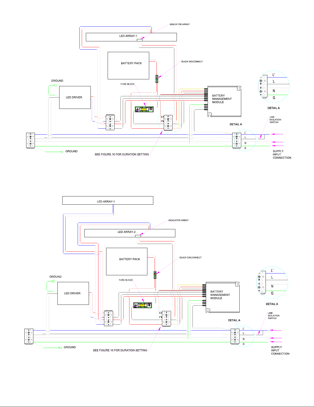
FIGURE 9A: STANDARD WIRING 4 WIRE CONNECTION LAYOUT WITH FIXED SCREW TERMINAL: 2FT
FIGURE 9B: STANDARD WIRING 4 WIRE CONNECTION LAYOUT WITH FIXED SCREW TERMINAL: 4FT
650610-000 Rev. 03 11/02/20 • Page 13 of 43Appleton • 1.800.621.1506 • www.appletonelec.com
 Loading...