

Appleton Instruction Sheet: Industrial Rigmaster LED Luminaire, 650609-001 | Appleton Manuals & Guides

650609-001 INSTRUCTION SHEET
Installation Instructions for the Appleton™ Rigmaster™ Industrial
LED Luminaire
FOR PROPER AND SAFE INSTALLATION OF THIS PRODUCT, PLEASE READ THE FOLLOWING INSTRUCTIONS.
Product Safety
Signal Words Defined
DANGER indicates a hazardous situation which, if not avoided, will result in death or serious injury. WARNING indicates a hazardous situation
which, if not avoided, could result in death or serious injury. CAUTION indicates a hazardous situation which, if not avoided, could result in minor or
moderate injury. NOTICE is used to address practices not related to physical injury.
Safety Instructions for Luminaire
WARNING:
• Do not open or remove luminaire when supply is ON.
• Do not use luminaire on ungrounded systems. Failure to ground this luminaire can result in an electric shock, which may be fatal.
• Disconnect the luminaire from the supply circuit before opening to reduce the risk of ignition. Keep tightly closed when in operation.
• Do not mount near gas or electric heaters.
• De-energize the unit ve (5) minutes before opening.
• Use two safety cables for installations experiencing high vibrations.
• Do not use on ungrounded 480-volt circuits.
• Supply wires to be rated for minimum 90°C.
CAUTION:
• Do not look directly at the LEDs when energized.
• Lens cleaning instructions: Wipe/clean from the outside only with a moist cloth. (Beware of electrostatic charges.)
• When installing, it is necessary that the reector, lens, and all certied conduit plugs be in place and tightened securely
to the housing.
NOTICE:
• Do not touch the LEDs; touching could leave oily deposits, causing hot spots and potential premature failure.
• The LED lens should be cleaned periodically from the outside only with a moist cloth to maintain lighting efciency.
• This luminaire is designed for and should be installed with wiring method required in accordance with the National Electrical Code
Canadian Electrical Code and all applicable local codes.
• This product must be installed in accordance with the applicable installation code by a person familiar with the construction and
operation of the product and hazards involved.
Applications/Intended Use
• Marine and wet locations; apply a corrosion-inhibiting grease, such as petroleum or soap thickened mineral oils, in 3 lines, spaced
approximately 120 degrees apart, perpendicular to the threads. Tighten all unused close-up plugs.
• Areas of low clearance, low ceiling heights, or where luminaire weights must be minimized.
• Non-hazardous locations where severe weather conditions, excessive moisture, dirt, dust, corrosive atmospheres, and high
ambient temperatures are encountered.
• Where exible cord is used, it should be approved for extra hard, wet location usage and shall have a separate ground conductor.
®
/
Appleton • 1.800.621.1506 • www.appletonelec.com 650609-001 Rev. 01 07/11/19 • Page 1 of 24
Agency Ratings : (NEC/CEC)
• Wet Locations
• Type 3R, 4 & 4X
• IP66
• Marine Outside Type (Salt Water) (For installations in USA only)
NOTES:
Refer to the product nameplate, located on the housing body, for details.
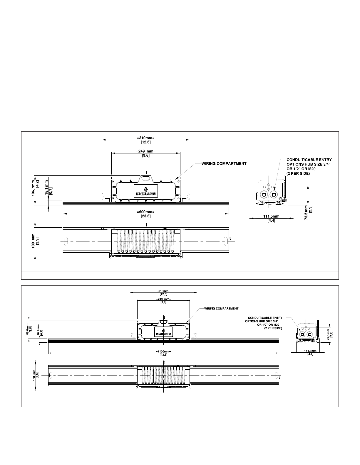
Dimensions/Details
LUMINAIRE DIMENSIONS
FIGURE 1: RIGMASTER 2 FT. LUMINAIRE
FIGURE 2: RIGMASTER 4 FT. LUMINAIRE
650609-001 Rev. 01 07/11/19 • Page 2 of 24Appleton • 1.800.621.1506 • www.appletonelec.com
Mounting Instructions
1. Make sure power is disconnected before installing the luminaire.
2. Determine appropriate mounting distance between mounting holes for your application.
3. Use bolts (not supplied) appropriate for the structural support member.
4. Secure luminaire to structural support element having through holes that can handle the weight of the luminaire in accordance with
5. Tighten the bolts to secure the luminaire in place.
local building code and all other code requirements.
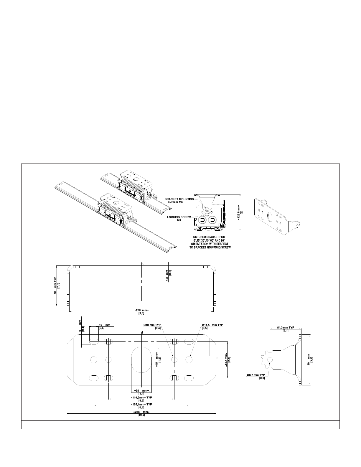
Mounting Brackets
SMALL SWIVEL BRACKET (RMSSB)
1. Make sure power is disconnected & circuit is de-energized before installing the bracket.
2. Determine appropriate mounting distance between holes on the brackets for your application. Refer to Figure 3.
3. Secure RMSSB bracket to structural support member with appropriate bolts (not supplied) that can handle the weight of luminaire
in accordance with local building code and all other code requirements.
4. Raise luminaire to mounted RMSSB bracket and secure it using M8 washer and bracket mounting screw M8 supplied with the
bracket on both sides. Refer to Figure 3 for hole locations.
5. Align the luminaire to the desired aiming position with your free hand and use Locking screw M8 supplied with the bracket to hold
at that position. Refer to Figure 3.
6. Tighten all the screws to secure the luminaire in place with a torque of 15 N.m (133 Lb.in)
FIGURE 3: MOUNTING OPTIONS – RMSSB BRACKET
650609-001 Rev. 01 07/11/19 • Page 3 of 24Appleton • 1.800.621.1506 • www.appletonelec.com
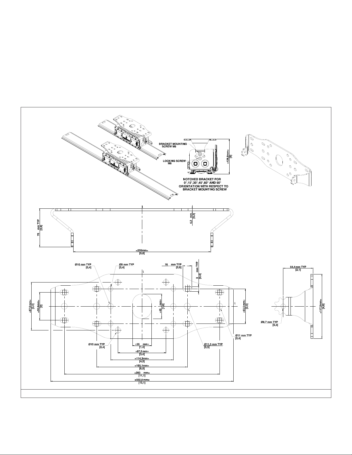
LARGE SWIVEL BRACKET (RMLSB)
1. Make sure power is disconnected & circuit is de-energized before installing the bracket.
2. Determine appropriate mounting distance between holes on the brackets for your application. Refer to Figure 4.
3. Secure RMLSB bracket to structural support member with appropriate bolts (not supplied) that can handle the weight of luminaire
4. Raise luminaire to mounted RMLSB bracket and secure it using M8 washer and bracket mounting screw M8 supplied with the
5. Align the luminaire to the desired aiming position with your free hand and use Locking screw M8 supplied with the bracket to hold
6. Tighten all the screws to secure the luminaire in place with a torque of 15 N.m (133 Lb.in)
in accordance with local building code and all other code requirements.
bracket on both sides. Refer to Figure 4 for hole locations.
at that position. Refer to Figure 4.
FIGURE 4: MOUNTING OPTIONS – RMLSB BRACKET
650609-001 Rev. 01 07/11/19 • Page 4 of 24Appleton • 1.800.621.1506 • www.appletonelec.com
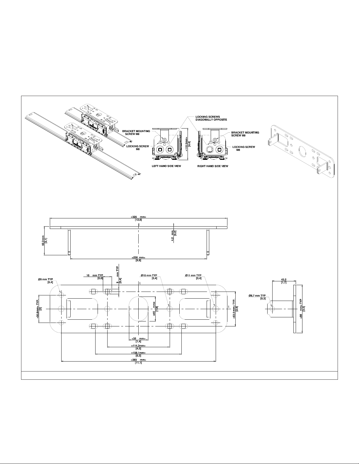
LOW PROFILE FIXED BRACKET (RMLPB)
1. Make sure power is disconnected & circuit is de-energized before installing the bracket.
2. Determine appropriate mounting distance between holes on the brackets for your application. Refer to Figure 5.
3. Secure RMLPB bracket to structural support member with appropriate bolts (not supplied) that can handle the weight of luminaire
4. Raise luminaire to mounted RMLPB bracket and secure using M8 washer and bracket mounting screw M8 supplied with the
5. Use locking screw M8 supplied with the bracket such that they are diagonally opposite to each other on either side. Refer to Figure
6. Tighten all the screws to secure the luminaire in place with a torque of 15 N.m (133 Lb.in)
in accordance with local building code and all other code requirements.
bracket on both sides. Refer to Figure 5.
5 for hole locations. Make sure bracket is locked to its position.
FIGURE 5: MOUNTING OPTIONS – RMLPB BRACKET
650609-001 Rev. 01 07/11/19 • Page 5 of 24Appleton • 1.800.621.1506 • www.appletonelec.com

Manufacturer Part Number
Crouse Hinds DP1057MTK X X
TABLE 1: MOUNTING BRACKET COMPATIBILITY CHART FOR RETROFIT INSTALLATIONS
Appleton Part Number
RMSSB
Small Swivel Bracket
RMLSB
Large Swivel Bracket
Low Profile Bracket
RMLPB
Dialight
AZZ™ Rigalite 53050 X X
Appleton™ Viamaster™ GRFC75A X
LTXW4 X X
LTXW4LP X X
Wiring
WARNING: The luminaire must be grounded as required by the National Electrical Code (Paragraph 410.21 and Article 250) or
Canadian Electrical Code (Rule 30-500 and Section 10). Verify that ground continuity has been established by using an Ohm meter or
other suitable testing equipment before energizing the luminaire. Failure to properly ground the luminaire will create an electric shock
hazard, which can cause serious injury or death.
Please use supply wires with temperature rating 90°C or above
Wiring the Rigmaster™ LED Luminaire with Wire Nut Option
Note: Each wire nut can accept 2 # AWG12 (user wires) with 1 # AWG18 wires (Luminaire wire). Use the appropriate wire gauge based on the
application. Refer to the table below for power system application.
TABLE 2
POWER SYSTEM BLACK WHITE GREEN
L-N AC POWER SYSTEM HOT / LINE NEUTRAL GROUND
L-L AC POWER SYSTEM HOT 1 / LINE 1 HOT 2 / LINE 2 GROUND
DC POWER SYSTEM +VE -VE GROUND
1. Make sure power is disconnected before wiring the luminaire.
2. A. Wiring with Cable: Strip the cable outer jacket as required. Strip the insulation of individual wire by
approximately 13 mm (0.5 in)
B. Wiring with Individual Wires: Strip the insulation of individual wire by approximately 13 mm (0.5 in)
3. For standard Wiring:
A. For Luminaire with ¾ inch hub size - Connect electrical power supply leads to the 3 wire conductors coming out of wiring
compartment with the help of wire nuts supplied with luminaire by holding wires together with even ends: see Figure 6.
After completing the wiring, insert wire nuts in wiring compartment through the Conduit / Cable entry hole. For Wiring
diagram refer to Figure 7, 8.
B. For Luminaire with ½ inch OR M20 hub size-
1. Open the luminaire wiring compartment by loosening the four captive screws. Allow the cover to swing open, enabling
access to the wiring compartment. See Figure 6. Pull in the luminaire’s supply input side driver wires (by removing wire
nuts) through the cable entry hole, inside the wiring compartment.
2. Pull in the facility electrical supply wires through the same conduit entry hole.
3. Connect electrical power supply leads to the 3 wire conductors with the help of wire nuts by holding wires together
with even ends. For Wiring diagram refer to Figure 7, 8.
4. Check all connections for continuity and ground integrity and close the luminaire wiring compartment cover.
5. Tighten the four captive screws by applying a torque of 2.25 N.m (20 Lb.in) using the sequence shown as in Figure 9.
Make sure wires do not pinch between cover and wiring compartment while closing.
650609-001 Rev. 01 07/11/19 • Page 6 of 24Appleton • 1.800.621.1506 • www.appletonelec.com

4. For through feed Wiring (for all conduit sizes):
6. For continuous row mounting, below mentioned number of luminaires can be connected.
7. Power can now be applied to the luminaire.
A. Open the luminaire wiring compartment by loosening the four captive screws. Allow the cover to swing open, enabling
access to the wiring compartment. See Figure 6. Pull in the luminaire’s supply input side driver wires (by removing wire
nuts) through the cable entry hole, inside the wiring compartment.
B. Pull in the facility electrical supply wires from both sides through the conduit entry holes on luminaire input side.
C. Connect electrical power supply leads to the respective wires with the help of wire nuts supplied with luminaire by holding
wires together with even ends. For Wiring diagram refer Figure 7, 8.
D. Check all connections for continuity and ground integrity and close the luminaire wiring compartment cover.
E. Tighten the four captive screws by applying a torque of 2.25 N.m (20 Lb.in) using the sequence shown as in Figure 9. Make
sure wires do not pinch between cover and wiring compartment while closing.
5. Apply TLNC4 grease on plugs (3 supplied) in 3 lines, spaced approximately 120 degrees apart, perpendicular to the threads.
After applying TLNC4 grease close all unused conduit entries with plugs. Apply torque of 45 N.m (400 Lb.in.) for 3/4" NPT
plug, 28 N.m (250 Lb.in.) for ½" NPT plug and 25 N.m (225 Lb. in.) for M20 plug.
Maximum 28 luminaires of 4300 lm. connected in series
Maximum 15 luminaires of 7600 lm. connected in series
FIGURE 6: RIGMASTER LUMINAIRE WITH WIRE NUT OPTION
650609-001 Rev. 01 07/11/19 • Page 7 of 24Appleton • 1.800.621.1506 • www.appletonelec.com
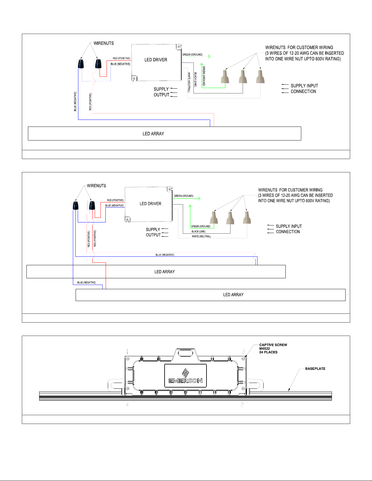
Wiring Diagrams
FIGURE 7: FOR RIGMASTER 2 FT LUMEN WITH WIRE NUTS FOR CUSTOMER WIRING
FIGURE 8: FOR RIGMASTER 4 FT WITH WIRE NUTS FOR CUSTOMER WIRING
FIGURE 9: SCREW TIGHTENING SEQUENCE
650609-001 Rev. 01 07/11/19 • Page 8 of 24Appleton • 1.800.621.1506 • www.appletonelec.com
 Loading...