

Instruction Sheet: Industrial Mercmaster LED Low Profile With Emergency Battery Backup, 650595-001 | Appleton
Appleton Instruction Sheet: Industrial Mercmaster LED Low Profile With Emergency Battery Backup, 650595-001 | Appleton Manuals & Guides

650595-001 INSTRUCTION SHEET
Installation Instructions for Appleton™ Industrial Mercmaster™ LED
Low Profile With Emergency Battery Backup
FOR PROPER AND SAFE INSTALLATION OF THIS PRODUCT, PLEASE READ THE FOLLOWING INSTRUCTIONS.
Product Safety
Signal Words Defined
DANGER indicates a hazardous situation which, if not avoided, will result in death or serious injury. WARNING indicates a hazardous
situation which, if not avoided, could result in death or serious injury. CAUTION indicates a hazardous situation which, if not avoided,
could result in minor or moderate injury. NOTICE is used to address practices not related to physical injury.
Safety Instructions for Complete Luminaire
WARNING:
• Do not open or remove the luminaire with the circuit energized.
• Do not remove or replace fuse when luminaire is energized.
• To avoid burning hands, allow luminaire to cool down prior to maintenance.
• Do not use this luminaire on ungrounded systems. Failure to ground the luminaire can result in an electric shock,
which may be fatal.
• Beware of electrostatic charges. Use a moist cloth to clean polycarbonate globe.
• Supply wires are to be rated for minimum 90°C.
CAUTION:
• Do not look directly at the LEDs when energized.
• Disconnect the luminaire from the supply circuit before opening.
• Disconnect battery pack through quick disconnect while opening luminaire for servicing.
• Do not attempt to service the battery. The unit uses a sealed, Ni-MH battery which requires no maintenance. For replacement,
contact Customer Service.
• It is necessary that the globe and all conduit plugs are tightly secured and all luminaire ttings (mounting hood and optic) are tightly
secured to the LED housing to prevent water and dust entry. The optic should be cleaned periodically to maintain lighting efciency.
NOTICE:
• Do not touch the LEDs; touching could leave oily deposits, causing hot spots and potential premature failure.
• This luminaire is designed for and should be installed in accordance with the National Electrical Code®/Canadian Electrical Code
and all applicable local codes.
• This product must be installed in accordance with the applicable installation code by a person familiar with the construction and
operation of the product and hazards involved.
• Do not use this equipment for anything other than its intended use.
• This luminaire is provided with a factory installed emergency lighting battery pack.
Appleton • 1.800.621.1506 • www.appletonelec.com 650595-001 Rev. B 01/17/19 • Page 1 of 50

Applications/Intended Use
• Disconnect the luminaire from the main supply circuit and wait until the battery gets de-energized (Minimum 90 minutes
for IMLLED*********H and minimum 180 minutes for IMLLED*********E) before opening the xture. Keep tightly closed when
in operation.
• Marine and wet locations: Apply a corrosion-inhibiting grease, such as petroleum or soap-thickened mineral oils, in 3 lines, spaced
approximately 120 degrees apart, perpendicular to the threads. Tighten all unused close-up plugs to a torque of 3.8 Nm min.
5.5 Nm max.
• Non-hazardous locations where severe weather conditions, excessive moisture, dirt, dust, corrosive atmospheres, and
high ambient temperatures are encountered.
• Luminaire to be mounted at a minimum of four (4) feet above the ground.
• Luminaire is suitable for mounting height less than fteen (15) feet above ground for 90 minute emergency duration.
• Luminaire is suitable for mounting height less than twelve (12) feet above ground for 180 minute emergency duration.
Agency Ratings j
• Wet Locations
• Type 4X
• IP66/67
NOTES:
j Refer to product nameplate, located on the exterior of the housing body for details.
650595-001 Rev. B 01/17/19 • Page 2 of 50Appleton • 1.800.621.1506 • www.appletonelec.com
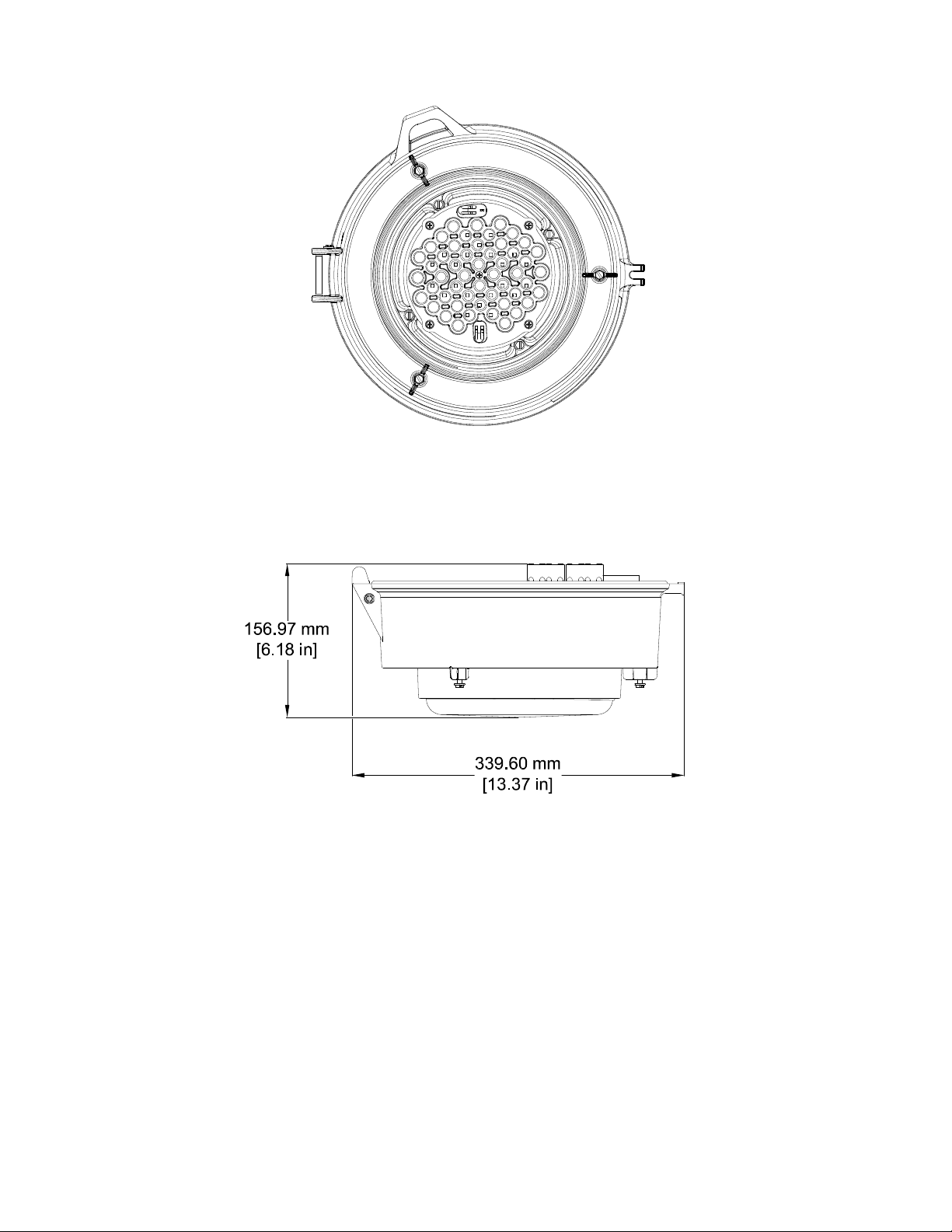
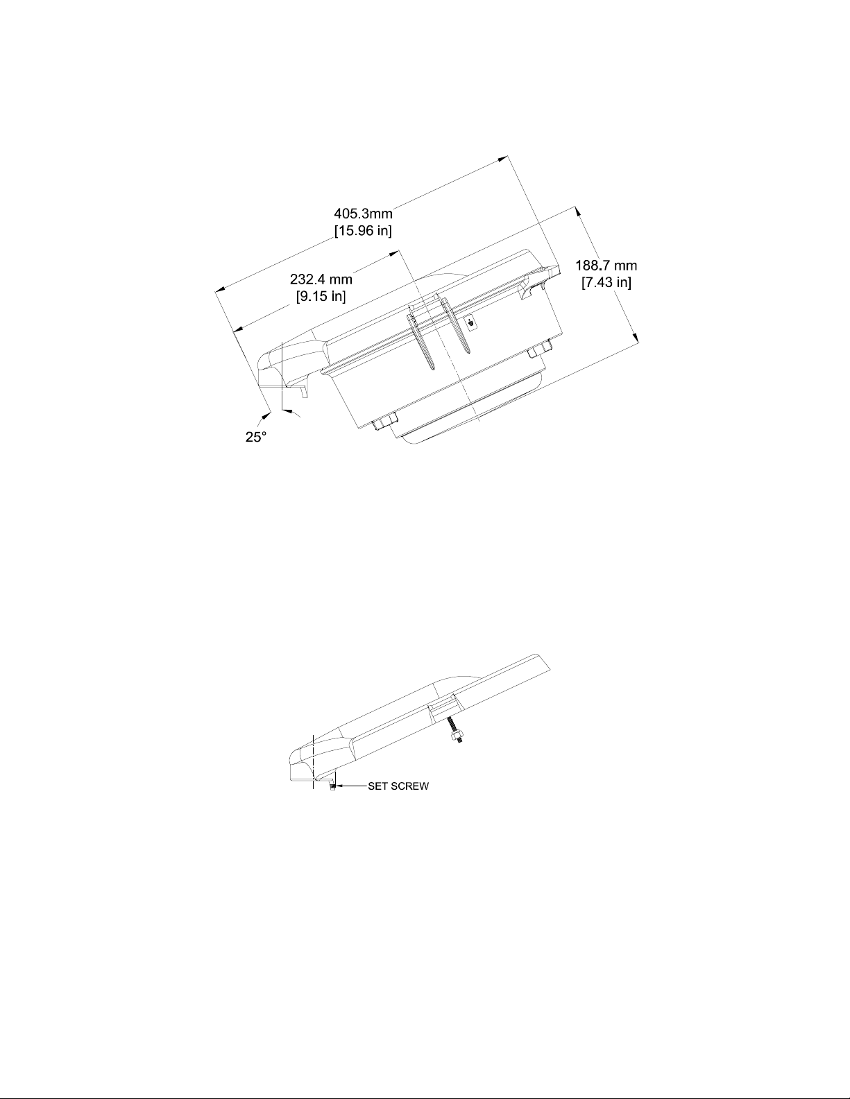
Luminaire Dimensions
FIGURE 1: MERCMASTER LED LOW PROFILE WITH EMERGENCY BATTERY BACKUP
650595-001 Rev. B 01/17/19 • Page 3 of 50Appleton • 1.800.621.1506 • www.appletonelec.com
Mounting Hood Dimensions and Installation
Pendant:
KPA-75, KPA-100
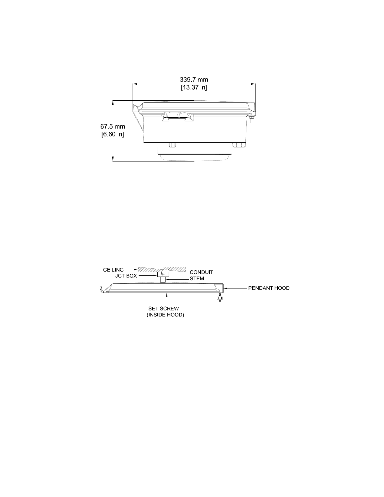
Dimensions:
FIGURE 2: LUMINAIRE WITH PENDANT HOOD
Installation:
1. Apply a corrosion-inhibiting grease, such as petroleum or soap-thickened mineral oils, in 3 lines, spaced approximately
120 degrees apart perpendicular to the threads on the conduit stem. Thread the pendant hood onto the 3/4 inch NPT or
1 inch NPT conduit stem.
2. Tighten the set screw inside the hood to a torque of 1.9 Nm min. 2.6 Nm max.
FIGURE 3: PENDANT HOOD DETAILS
650595-001 Rev. B 01/17/19 • Page 4 of 50Appleton • 1.800.621.1506 • www.appletonelec.com
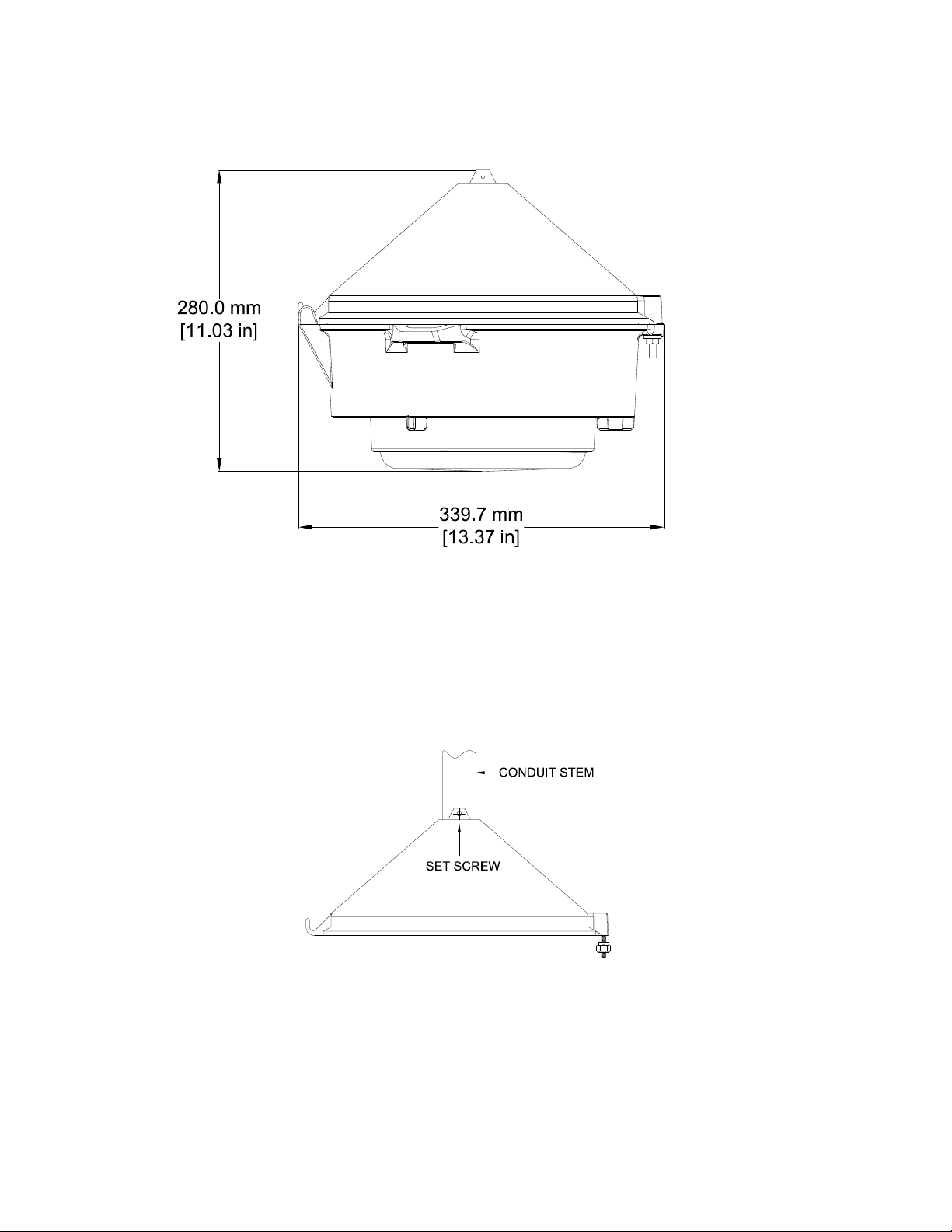
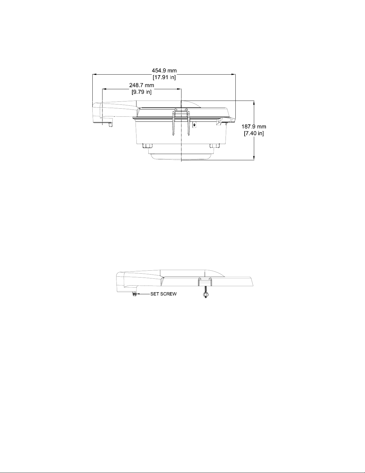
Pendant Cone:
KPCH-75, KPCH-100
Dimensions:
FIGURE 4: LUMINAIRE WITH PENDANT CONE
Installation:
1. Apply a corrosion-inhibiting grease, such as petroleum or soap-thickened mineral oils, in 3 lines, spaced approximately
120 degrees apart perpendicular to the threads on the conduit stem.
2. Thread the pendant cone hood onto the 3/4 inch NPT or 1 inch NPT conduit stem.
3. Tighten the set screw to a torque of 1.9 Nm min. 2.6 Nm max.
FIGURE 5: PENDANT CONE HOOD DETAILS
650595-001 Rev. B 01/17/19 • Page 5 of 50Appleton • 1.800.621.1506 • www.appletonelec.com
Watertight Pendant*:
245.6 mm
[9.67 in]
274.3 mm
[10.80 in]
339.7 mm
[13.37 in]
BIG PRIMO
LOW PROFILE 1.5
Ø374.7 mm
[14.75 in]
Ø374.7 mm
[14.75 in]
Ø374.7 mm
[14.75 in]
Ø374.7 mm
[14.75 in]
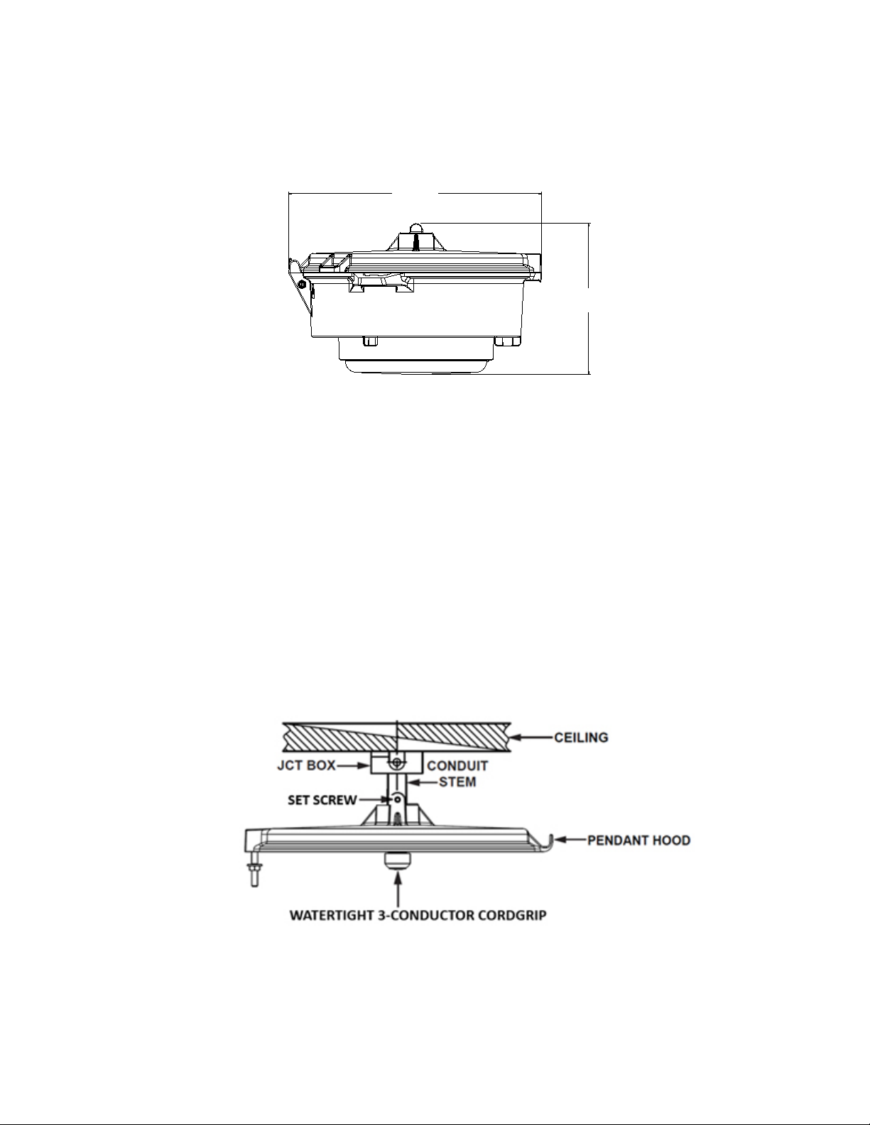
KPA-75WT, KPA-100WT
Dimensions:
339.7 mm
[13.37 in]
FIGURE 6: LUMINAIRE WITH WATERTIGHT PENDANT HOOD
203.6 mm
[8.01 in]
Installation with Conductor Cordgrip:
1. Apply a corrosion-inhibiting grease, such as petroleum or soap-thickened mineral oils, in 3 lines, spaced approximately
120 degrees apart perpendicular to the threads on the conduit stem. Thread the pendant hood onto the 3/4 inch or
1 inch conduit stem.
2. Tighten the set screw located on the top side of the hood to a torque of 1.9 Nm min. 2.6 Nm max.
3. Remove the watertight 3-conductor cordgrip, which comes installed in the mounting hood from the factory.
4. Feed the supply wires through the conduit entry in the mounting hood, then individually thread each wire into the smaller holes in
the cordgrip. NOTE: Each of the three (3) holes need to be occupied by a conductor for the unit to be considered watertight.
5. Thread the cordgrip with the conductors installed into the NPT entry on the underside of the hood until wrench tight.
6. Thread the sealing nut onto the multi-hole gland until hand tight, ensuring a rm grip and seal on the conductors.
FIGURE 7: PENDANT HOOD DETAILS (WATERTIGHT 3-CONDUCTOR VERSION)
*Certified for cCSAus only.
650595-001 Rev. B 01/17/19 • Page 6 of 50Appleton • 1.800.621.1506 • www.appletonelec.com
Watertight Pendant*:
KPA-75WT, KPA-100WT (Continued)
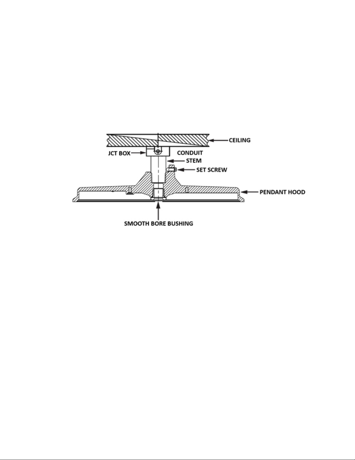
Installation with Smooth Bore Bushing:
1. Pendant hood comes shipped with a smooth bore bushing installed to protect input wires from abrasion during use.
DO NOT REMOVE.
2. Apply a corrosion-inhibiting grease, such as petroleum or soap-thickened mineral oils, in 3 lines, spaced approximately
120 degrees apart perpendicular to the threads on the conduit stem. Thread the pendant hood onto the 3/4 inch or
1 inch conduit stem.
3. Tighten the set screw located on the top side of the hood to a torque of 1.9 Nm min. 2.6 Nm max.
FIGURE 8: PENDANT HOOD DETAILS (SMOOTH BORE BUSHING VERSION)
*Certified for cCSAus only.
650595-001 Rev. B 01/17/19 • Page 7 of 50Appleton • 1.800.621.1506 • www.appletonelec.com
Ceiling:
KPC-75, KPC-100
Dimensions:
FIGURE 9: LUMINAIRE WITH CEILING HOOD
Installation:
1. Bolt the ceiling hood directly to a structural member; thread onto a 3/4 inch NPT or 1 inch NPT conduit stem.
2. Remove unused conduit plugs and reinstall with a corrosion-inhibiting grease, such as petroleum or soap-thickened mineral oils,
in 3 lines, spaced approximately 120 degrees apart perpendicular to the threads on the conduit plugs. Tighten to a torque of
3.8 Nm min. 5.5 Nm max.
FIGURE 10: CEILING HOOD DETAILS
650595-001 Rev. B 01/17/19 • Page 8 of 50Appleton • 1.800.621.1506 • www.appletonelec.com
Trunnion:
KPCT-75, KPCT-100
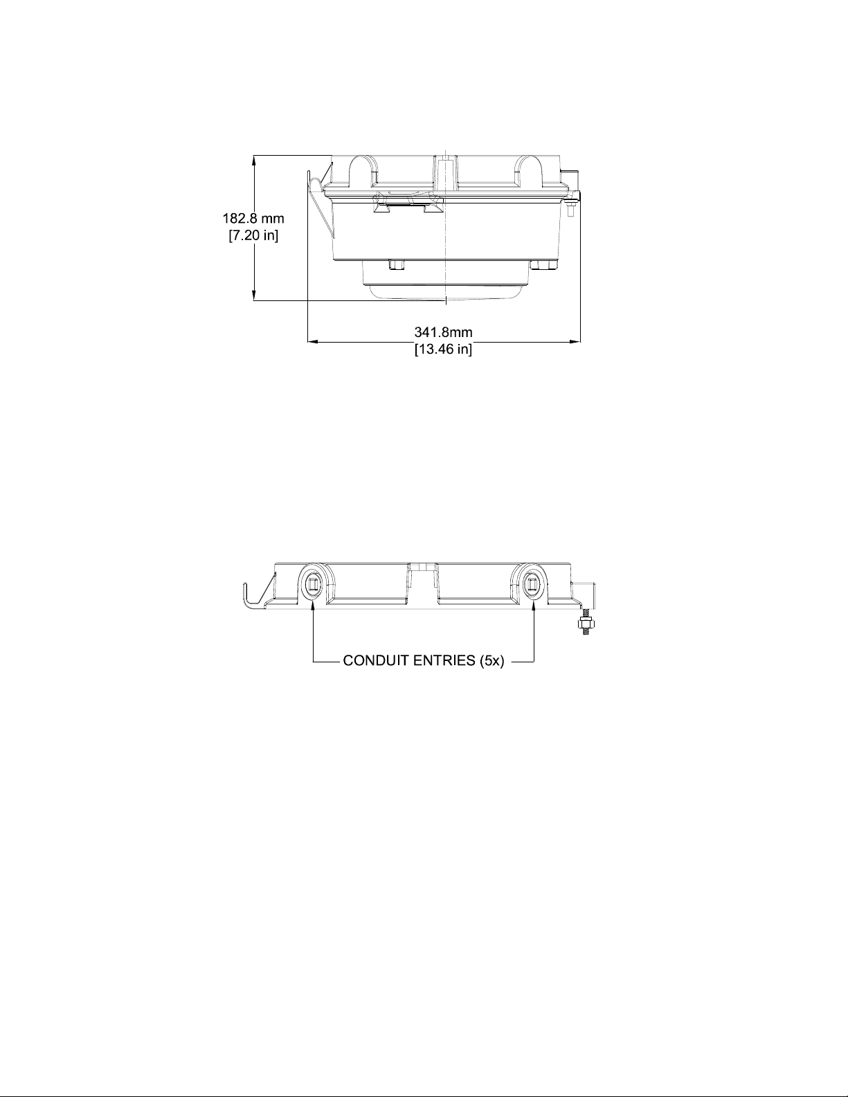
Dimensions:
FIGURE 11: LUMINAIRE WITH TRUNNION HOOD
Installation:
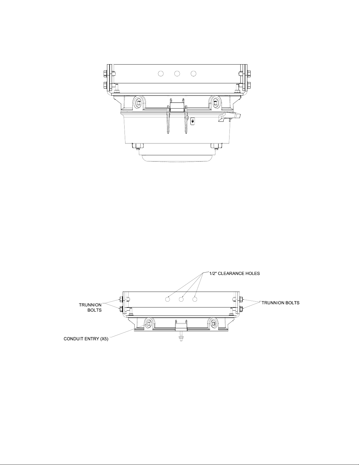
1. Mount the trunnion hood directly to a at surface using user-supplied hardware appropriate for the mounting surface.
NOTE: The trunnion has a center clearance hole for a 1/2 inch bolt and two 1/2 inch clearance holes spaced 3-1/2 inches apart on
the trunnion center line.
2. Slightly loosen the four (4) trunnion bolts and tilt the luminaire to the desired position with your free hand.
3. Retighten the bolts to secure the luminaire in place.
4. Remove unused conduit plugs and reinstall with a corrosion-inhibiting grease, such as petroleum or soap-thickened mineral oils,
in 3 lines, spaced approximately 120 degrees apart, perpendicular to the threads on the conduit plugs.
FIGURE 12: TRUNNION HOOD DETAILS
650595-001 Rev. B 01/17/19 • Page 9 of 50Appleton • 1.800.621.1506 • www.appletonelec.com
Wall:
KPWB-75, KPWB-100
Dimensions:
FIGURE 13: LUMINAIRE WITH WALL HOOD
Installation:
1. Bolt the wall hood to a structural member.
2. Remove unused conduit plugs and reinstall a corrosion-inhibiting grease, such as petroleum or soap-thickened mineral oils,
in 3 lines, spaced approximately 120 degrees apart perpendicular to the threads on the conduit plugs. Tighten to a torque of
3.8 Nm min. 5.5 Nm max.
FIGURE 14: WALL HOOD DETAILS
650595-001 Rev. B 01/17/19 • Page 10 of 50Appleton • 1.800.621.1506 • www.appletonelec.com
25° Stanchion:
KPS-125, KPS-150
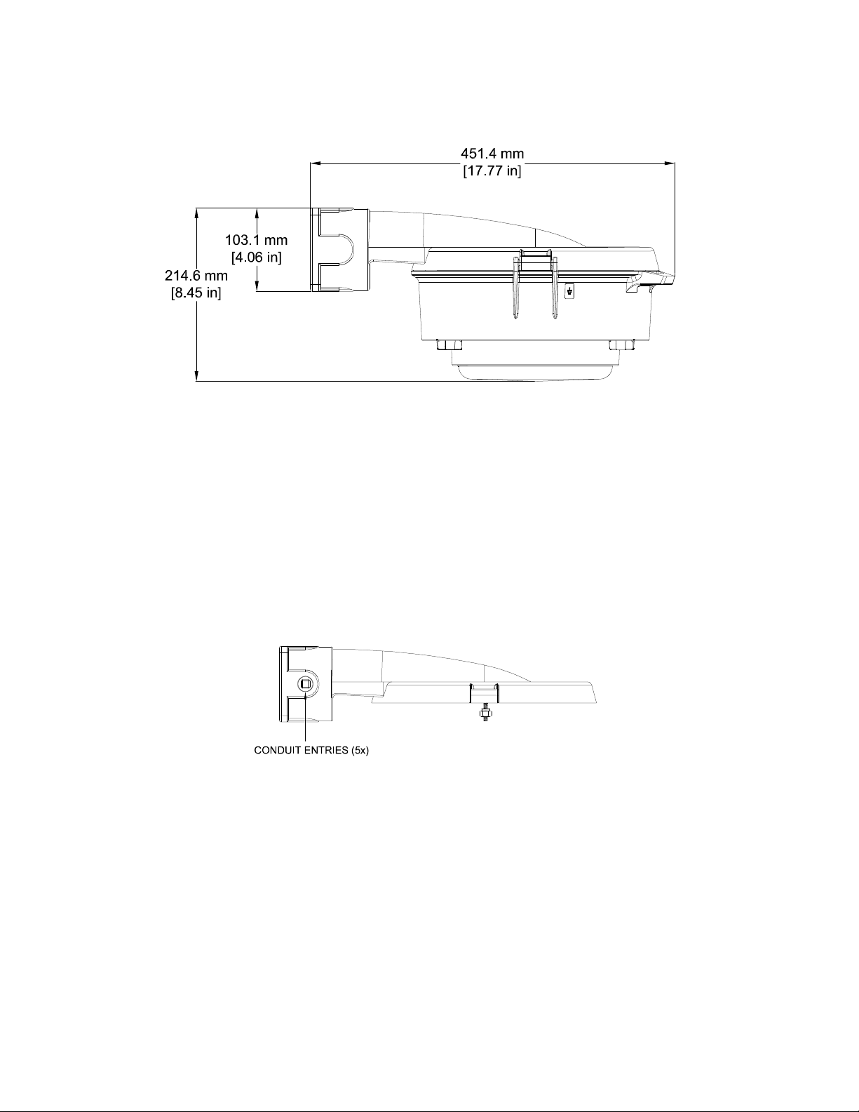
Dimensions:
FIGURE 15: LUMINAIRE WITH 25° STANCHION HOOD
Installation:
1. Apply a corrosion-inhibiting grease, such as petroleum or soap-thickened mineral oils, in 3 lines, spaced approximately
120 degrees apart perpendicular to the threads on the conduit.
2. Thread the stanchion hood onto the 1-1/4 inch NPT or 1-1/2 inch NPT conduit. NOTE: Five (5) full threads must be engaged.
3. Determine the appropriate orientation and tighten the set screw to a torque of 1.9 Nm min. 2.6 Nm max.
FIGURE 16: 25° STANCHION HOOD DETAILS
650595-001 Rev. B 01/17/19 • Page 11 of 50Appleton • 1.800.621.1506 • www.appletonelec.com
90° Stanchion:
KPST-125, KPST-150
Dimensions:
FIGURE 17: LUMINAIRE WITH 90° STANCHION HOOD
Installation:
1. Apply a corrosion-inhibiting grease, such as petroleum or soap-thickened mineral oils, in 3 lines, spaced approximately
120 degrees apart perpendicular to the threads on the conduit stem. Thread the stanchion hood onto the 1-1/4 inch NPT or
1-1/2 inch NPT conduit stem. NOTE: Five (5) full threads must be engaged.
2. Determine the appropriate orientation and tighten the set screw to a torque of 1.9 Nm min. 2.6 Nm max.
FIGURE 18: 90° STANCHION HOOD DETAILS
650595-001 Rev. B 01/17/19 • Page 12 of 50Appleton • 1.800.621.1506 • www.appletonelec.com
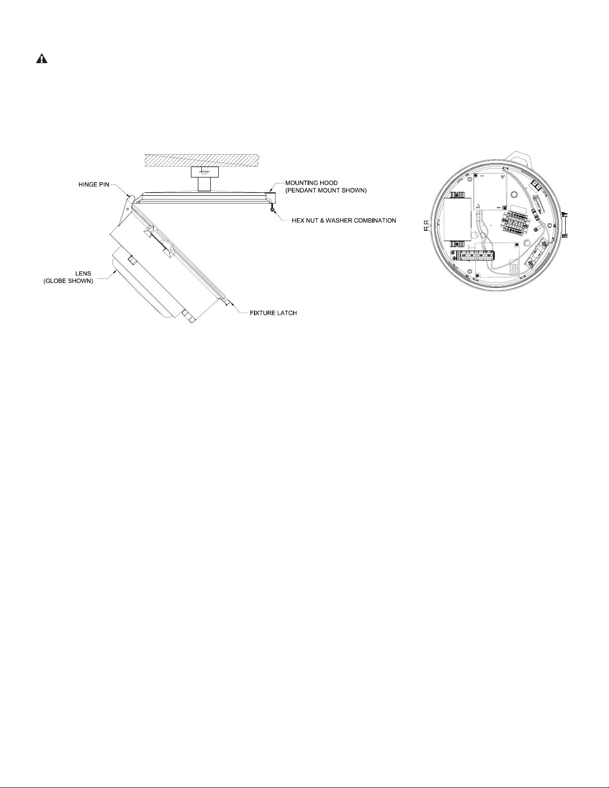
LED Housing Installation
WARNING: The luminaire must be grounded as required by the National Electrical Code (Paragraph 410-21 and Article 250) or
Canadian Electrical Code (Rule 30-500 and Section 10). Verify that ground continuity has been established by using an Ohm meter
or other suitable test equipment before energizing the luminaire. Failure to properly ground the luminaire will create an electric shock
hazard, which can cause serious injury or death.
FIGURE 19: WIRING COMPARTMENT
1. Disconnect facility power to the electric power supply leads.
2. Feed the proper temperature supply wires through the conduit entry in the mounting hood.
3. Hang the LED housing on the hinge; align with the hinge pin.
4. Strip the individual conductors to bare wire and insert them into the proper terminal block connections. The connection points
are identied on the terminal block as: “L” = Line, “N” = Neutral, and “G” = Ground. Tighten down the terminal block screws onto
the wire to a torque of 0.6 Nm min. 0.8 Nm max.
5. Housing requires grounding to mounting hood. Connect internal housing ground wire to GREEN ground screw in the
mounting hood.
6. Check all connections for continuity and ground integrity.
7. Fold all excess supply leads and fasten them into the mounting hood with the wire tie (supplied) to avoid pinching the wires.
8. Swing the LED housing up and tightly secure with the hex nut and washer combination.
9. Close all unused conduit entries to a torque of 3.8 Nm min. 5.5 Nm max. Install supplied conduit plug engaging at least three (3)
full threads with corrosion-inhibiting grease, such as petroleum or soap-thickened mineral oils, in 3 lines, spaced approximately
120 degrees apart, perpendicular to the threads.
10. Apply AC power to the unit. LED indicator on to the luminaire should begin to ash green. If it ashes red; please refer to the
Troubleshooting/Maintenance section on Page 16.
11. Battery will be fully charged within 24 hours (maximum). Emergency lamps may or may not light at this time, depending on the
battery charge.
650595-001 Rev. B 01/17/19 • Page 13 of 50Appleton • 1.800.621.1506 • www.appletonelec.com
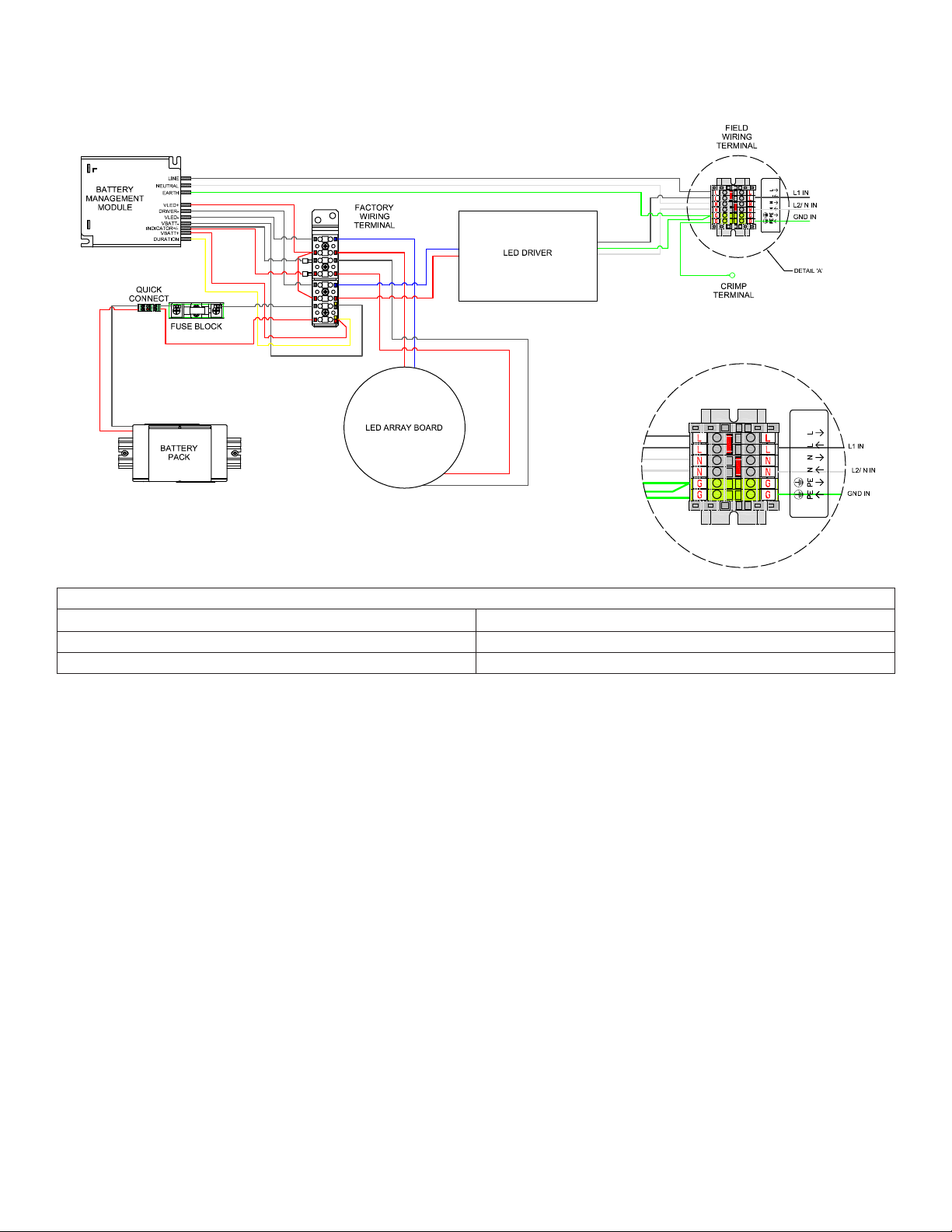
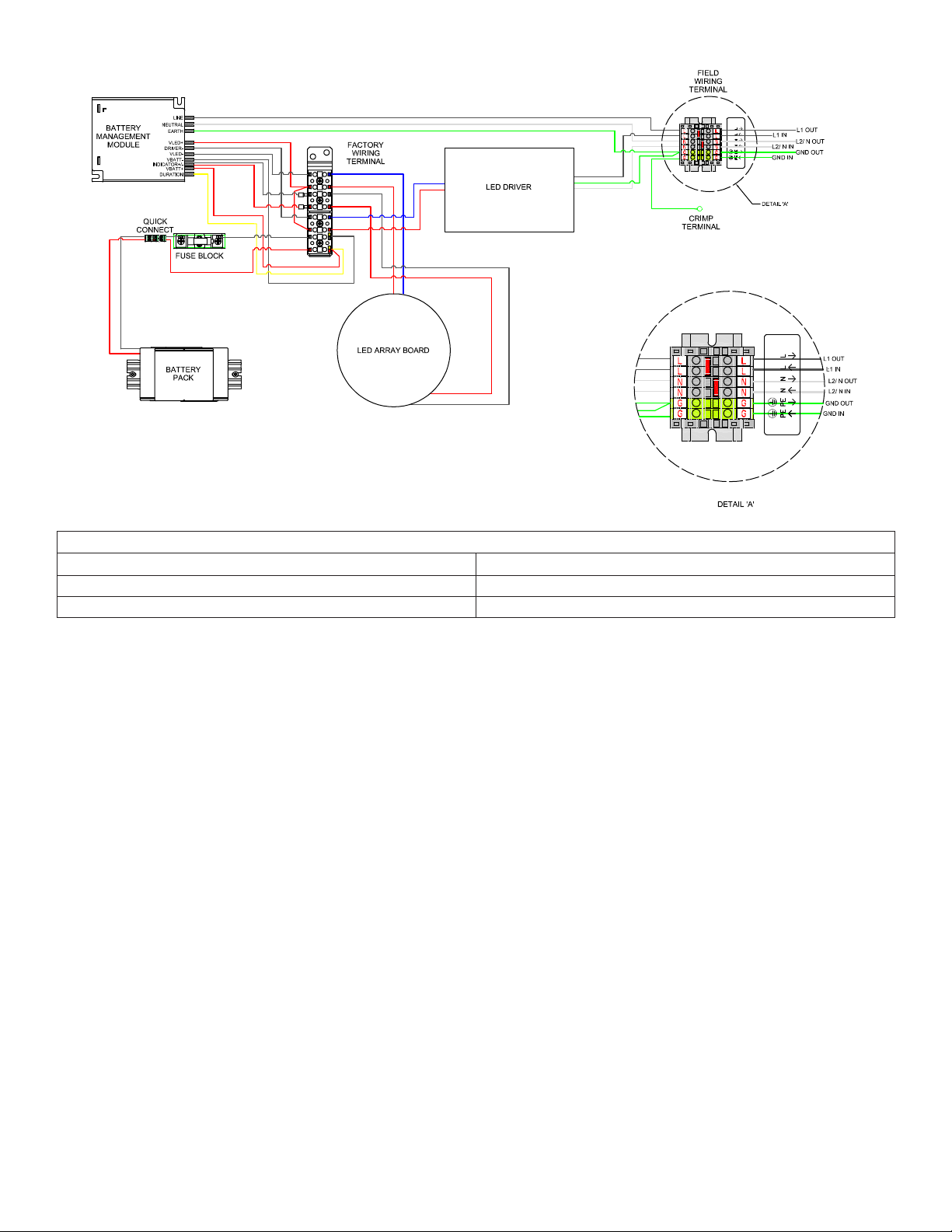
Wiring Diagrams
Complete the wire connections per the appropriate diagram below.
Connection Data (All Wires)
Conductor cross section AWG Minimum 18 AWG
Conductor cross section AWG Maximum 10 AWG
Stripping Length 9mm/0.35 in.
FIGURE 20A: STANDARD WIRING METHOD 90 MINUTE SETTING
650595-001 Rev. B 01/17/19 • Page 14 of 50Appleton • 1.800.621.1506 • www.appletonelec.com
Connection Data (All Wires)
Conductor cross section AWG Minimum 18 AWG
Conductor cross section AWG Maximum 10 AWG
Stripping Length 9mm/0.35 in.
FIGURE 20B: LOOP IN LOOP OUT WIRING METHOD 90 MINUTE SETTING
650595-001 Rev. B 01/17/19 • Page 15 of 50Appleton • 1.800.621.1506 • www.appletonelec.com
 Loading...