

Appleton Instruction Sheet: FD Hazardous Locations Luminaires, 650352001 | Appleton Manuals & Guides
650352-001
INSTALLATION INSTRUCTIONS FOR
FD SERIES FLUORESCENT FIXTURES
INSTALLATION INSTRUCTIONS FOR FD SERIES FLUORESCENT FIXTURES
IMPORTANT: This fixture is designed for permanent installation in Clas I, Div. 2 and wet locations in accordance with the National
Electric Code and all applicable local codes.
• DO NOT OPEN OR REMOVE FIXTURE WHILE IT IS ENERGIZED.
• DO NOT USE FIXTURE ON UN-GROUNDED CIRCUITS. Failure to ground this fixture can result in an electrical shock which
may be fatal.
• Do Not use in areas of limited ventilation or in high ambient areas (above 40 deg. C).
• Lens should be cleaned periodically for high light output.
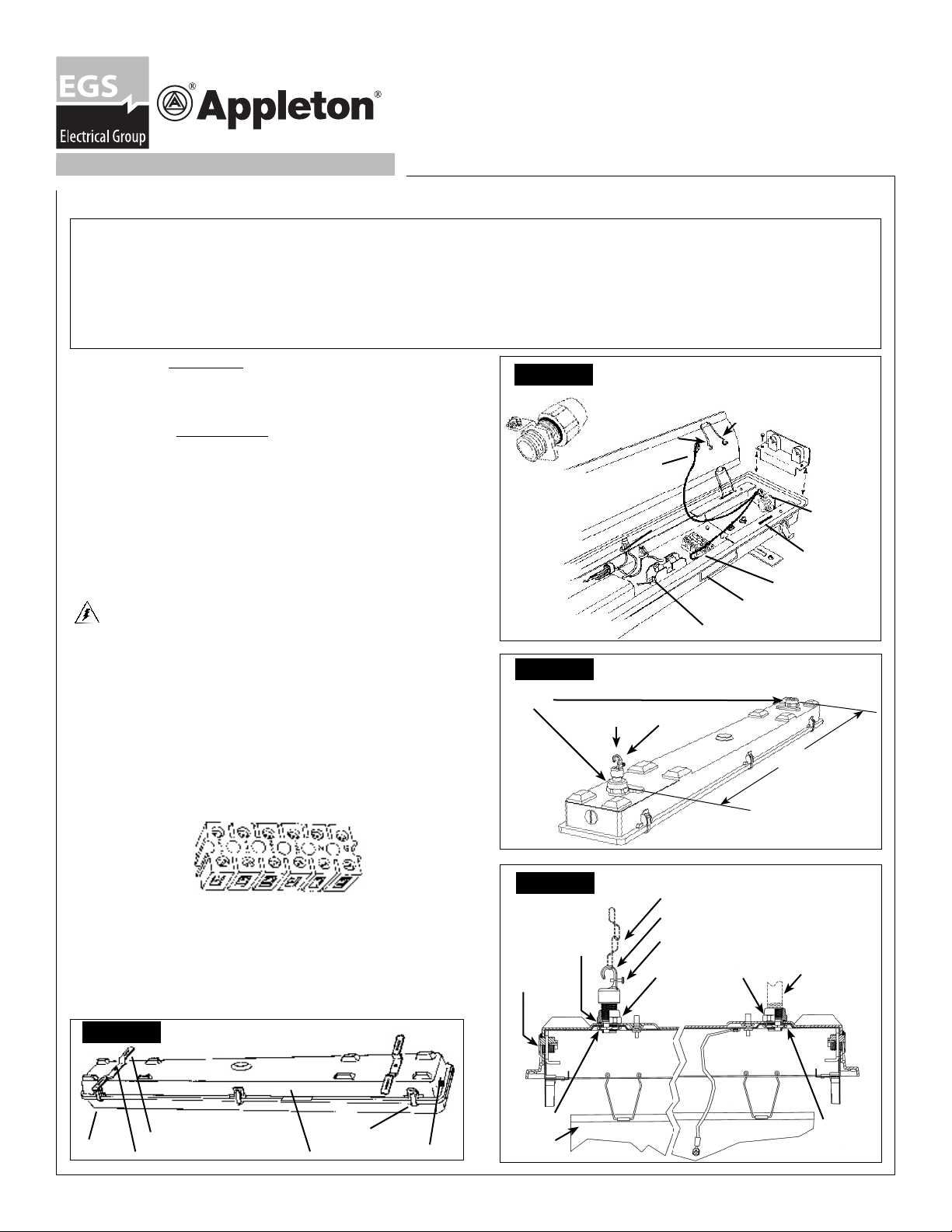
CEILING MOUNT. SEE FIGURE 1.
1(a). Attach the mounting brackets to the brass studs on the fixture.
(b).
In case of hook and chain mounting option, use the ceiling
brackets to connect the fixture to the chain.
PENDANT MOUNT. SEE FIGURE 3 &4.
2. Remove lens from enclosure by opening latches. Snap off one
side of reflector to ensure that conduit hub is securely engaged
with locknut.
3. Install the fixture housing in accordance with local building
code and all applicable local codes.
4. Pull supply wires through conduit system and into the lighting
fixture. Use supply wire rated at least 60°C.
5. Hinge the reflector to one side by detaching the springs from one
side of the fixture housing. Refer to
WIRING
FIGURE 2- conduit hub installed.
• Ground wire, if present, should be secured to green grounding
screw in fixture housing.
• Connect the black and white leads from conduit to proper ballast leads.
• If fixture contains an optional terminal block, connect the black,
white and the grounding lead from conduit to proper terminals
on the terminal block.
• Note: The wire range for the terminal block is #8—#18AWG.
Terminal block lugs to be tightened to 12 in. lb.
Note: Terminal block positions are labeled.
Figure 2
REFLECTOR
Figure 3
1/2” NPT
HUB
1/2" NPT Hub with Grounding Lug.
REFLECTOR SPRING, PUSH
TOGETHER AND PULL UP.
GROUNDING
WIRE (GREEN)
BALLAST
NAMEPLATE
FUSE KIT (OPTIONAL)
PENDANT MOUNT
FIXTURE
HOOK
LOCKING
SCREW
NO NEED
TO REMOVE
SOCKET
ASSEMBLY
GROUNDING
LUG ON ENTRY
HUB
SPRING SLOT IN
END BRACKET
TERMINAL BLOCK
(OPTIONAL)
1
41
/
”
2
• Close the reflector by pushing the reflector springs together and
putting ends of springs into slots in fixture end brackets. Push
reflector inward onto end brackets to secure in place.
6. Install lamps, checking both lamp type and wattage for proper lamp.
7. Install the lens, by closing the latches until lens is fully seated
Figure 4
SEALTITE GASKET
CLOSE UP
PLUG
PENDANT MOUNT
CHAIN NOT PROVIDED
FIXTURE HOOK
SCREW AND
WASHER
CONDUIT HUB
1/2" PIPE
SEALANT BY
OTHERS
against the fixture gasket. (Dimensions on pg. 2)
Figure 1
LENS
EGS Electrical Group • www.appletonelec.com • 800-621-1506 Rev. C 07/20/2007 Page 1
FIXTURE OVERVIEW
MOUNTING BRACKETS
BRASS STUDS
LATCH
NAMEPLATE
HUB
LOCKNUT
REFLECTOR
LOCKNUT
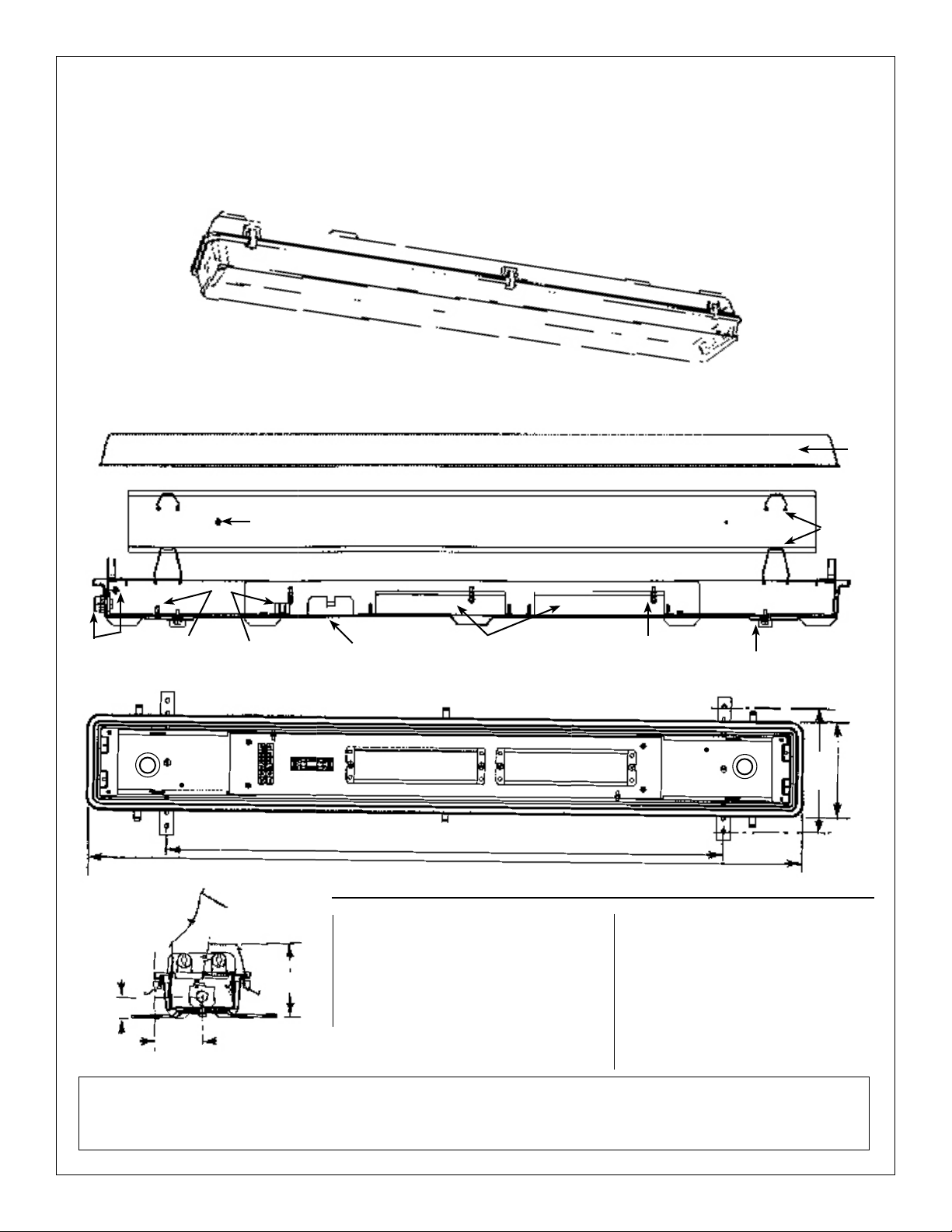
Four Foot, Two Lamp, Non-Metallic Fluorescent Lighting Fixtures For
Class I, Division 2, Class I, Zone 2 and Wet Locations
Rated for Wet-Locations only when using Acrylic Lens, Catalog Number FLENS.
Rated at IP 65, Dust-Proof and Jet Water-Proof,only when using Polycarbonate Lens, Catalog Number FPLENS.
STANDARD TWO BALLAST FIXTURE
Lens
Hub with
Ground Lug
C
1/
L
1
(4) Reflector
Hinge Springs
(2) Each End
"
4
1/
1/
8
"
2
6
Grounding
Screw
Reflector
Grounding Screw
Terminal Block
Fuse Kit
38
3/
4
Two Ballast
"
Latch Assembly
(3) On Each Side
Mounting Brackets
(1) On Each End
50"
Standard Materials
• Housing: Fiberglass reinforced polyester.
• Lens : •-Acrylic (General Usage)
1/
"
5
2
"
2
C
1/
"
3
4
L
•-Polycarbonate Lens must be
used for IP65 Rating
• Gasket: Non-Thixotropic Polyol.
• Hubs: Die cast aluminum (1/2" NPT).
• Lampholders: Polycarbonate.
• Cord Connector: Polyamide
Standard Finishes
• Housing: White color finish.
• Latches: White color finish.
Compliances
FD Series: • Class I, Division 2,
• Class I, Zone 2, and
• Wet-Locations.
All statements, technical information and recommendations herein are based upon data and tests believed to be reliable. The accuracy
or completeness of such data or test results are not guaranteed. Pursuant to EGS Electrical Group - Appleton Electric, LLC ÒTerms and
Conditions of Sale", because Appleton Electric, LLC neither knows nor controls the applications or conditions in which the product will be
used, purchaser must determine the appropriateness for the intended use of the product in such applications or conditions.
Page 2 650352-001 Rev. C 07/20/2007 EGS Electrical Group • www.appletonelec.com • 800-621-1506
 Loading...