

Appleton Instruction Sheet: ATEX/IECEx Viamaster LED Series Luminaires, 250065014 | Appleton Manuals & Guides
VIAMASTER LED - Série LLEDA
VIAMASTER LED - Series LLEDA
E
quipem
ent / E
quipm
ent
N
iveau de protection / P
M
ode de protection / P
Tem
pérature am
C
ertificat AT
C
ertificat IE
C
odes IP &
U
T
IL
IS A
T
IO
N
-
n
t
é
être
ent. (C
l’objet
s
s
u
US E
de
r
l
e
s
certifiés
orps : A
la
présente
p
a
r
o
avec
lum
1
F
R
Les
produits
les zones et les conditions pour lesquelles ils ont été certifiés (voir tableau ci-dessus)
L
e
s
a
c
c
bouchons
certification du m
C
o
rro
sio
avec votre environnem
faisant
e
s
s
o
i
r
e
s
m
o
etc.,
doivent
atériel.
n
:
Il convient de s’assurer que les m
E
X
C
E
IK
/ IP &
notice
i
s
d
’
e
n
v
e
l
o
p
le
matériel
atériaux des appareils sont com
inium
- Vasque : P
biante / A
/ AT
E
x / IE
ne
p
e
,
ou
rotection level
rotection m
m
X
C
ertificate
C
E
x C
ertificate
IK
C
odes
doivent
t
e
l
s
q
u
d’un
type
olycarbonate)
ode
bient tem
être
utilisés
e
:
e
n
t
compatible
perature
r
é
e
s
que
d
e
patibles
dans
c
â
avec
G
B
P
roducts
zones and conditions for w
T
he
b
l
e
la
accessories
,
blanking plugs, term
C
o
rro
sio
w
ith your environm
E
P
E
x nA IIC
LC
IE
covered
n
:
You should m
NT 250 0650/04
II3 G
D
L G
c / E
P
L D
c
/ E
x tc IIIC
- 20°
C
ou/or - 40°
15 AT
E
X
1003X
IE
C
under
this
technical
hich they have been certified (see the table above).
m
ounted
in
or
on
inals, m
ent. ((H
the
ust be certified for the intended use.
ake sure that the m
ousing: A
lum
C
E
x LC
IE
15.0010X
IP
66 - IK
instructions
sides
of
the
aterial of the equipm
inum
- Lens: P
à/to +
65°
08
leaflet
enclosures,
olycarbonate)
LC
C
IE
II2 D
E
P
E
x tb IIIC
15 AT
shall
such
L D
b
E
X
3006X
only
be
as
:
cable
ent is com
used
patible
in
the
glands,
C
O N D I
T
I
O N S S
P
É
C I
A L
E
S
- SP
E
C I
2
Classe de températures & Températures de surface / Temperatures class & Surface temperatures
Séries / Series
LLEDA...2 ..*BU(**LU)Z2... T6 (75°C) T5 (90°C) T5 (95°C) T5 (100°C) T54°C T69°C T74°C T79°C
LLEDA...5 ..*BU(**LU)Z2... T4 (129°C) T3 (144°C) T3 (148°C) / T64°C T79°C T84°C /
LLEDA...7 ..*BU(**LU)Z2... T4 (130°C) T3 (145°C) T3 (149°C) / T64°C T79°C T84°C /
Protection contre la surtension transitoire 2kV (1,2/ 50 Hz) *BU - driver operating temperature -20°C
Protection against impulse voltage 2kV (1,2/ 50 Hz) **LU - driver operating temperature -40°C
I
NS TAL L
3
F
R
L
e
ma
D
irective utilisateur 99/92/C
La zone d’installation doit être en adéquation avec la catégorie du produit.
L’in stallation du maté rie l doit être réalisée selo n les prescriptions de la norme
d
’ins
tallation
Le
p
ers
onne
An
ne
x
e
A)
L
e
ra
ccorde
compte
du co
T
oute
o
pér
co
nst
ruct
t
é
r
i
e
l
d
EN/IE
l in
ter
me
n
t des
urant maxima
at
io
n n’ét
e
u
r d
égag
o
ven
C
ATI
i
t
ê
e
Ta +40°C Ta +55°C Ta +60°C Ta +65°C Ta +40°C Ta +55°C Ta +60°C Ta +65°C
ON
- I
t
r
e
s
60
079-
an
t d
c
o
nd
ant pas
c
e
de
é
E
oit ê
u
le admiss
NS TAL L
l
e
c
t
i
o
.
1
4.
tre qualifié pour
cte
urs
ef
f
ect
rn
ier de toute respo
n
n
é
c
o
n
d
oit
ê
tre ré
ible.
uée confor
f
o
ATI
r
mé
ON
me
l’activ
alisé
mément
nsabilit
A L C O N D I
Gaz / Gas Poussières / Dust
n
t
a
u
x
e
x
i
g
e
n
ité c
ons
idér
ée (EN/IEC 60079-14
se
lon
les
rè
gle
aux instruc
é.
c
e
s
d
s
d
tions
T
I
O N S
é
f
i
n
i
e
s
d
e
l’art en tenant
G
B
A
ll equipm
a
n
s
l
a
D
irective 99/92/E
T
he product category shall m
Al
l
hardware shal
EN/IEC 60079-14.
All personnel involved in the installation process shall be qualified for the roles
performed (EN/IEC 60079-14 Annexe A).
Equipment must be connected as stipulated by the regulations in force in accordance with
the maximum permissible current.
We shall be absolved from all responsibility for operations performed on
enclosures without our formal consent.
ent shall be selected in com
C
for users.
l
be i
atch the installation zone.
nst
al
l
ed as st
i
pul
at
pliance w
ed under el
ith the requirem
ect
ri
cal
i
nst
ents stipulated in
al
l
at
i
ons st
andard
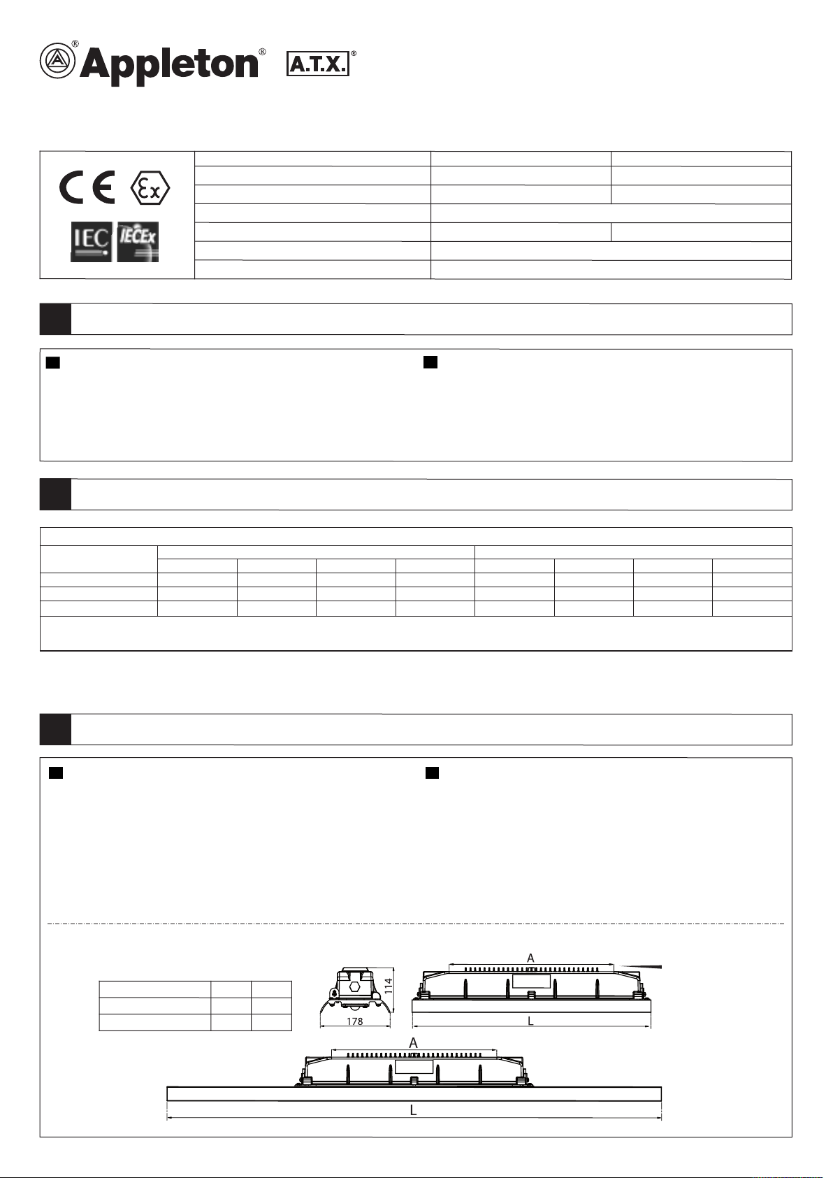
Côtes
O
v
e
r
d’enc
ombr
all dime
ement
ns
ions (mm)
S
ér
LLEDA...2 & LLEDA...5 610
LLEDA...7 1220
(
mm)
ie
L
A
400
400
M8
1/3
A
700
30
20
0,5
45
10
5
2
32
2
00
M
8
M8
50
30
Ø
5
4
Ø
1
0
,2
M
A
X
.
Ø
9
6
2
8
4
20
M8
13 MAX.
8
9
5,9
1
3 MAX.
M8
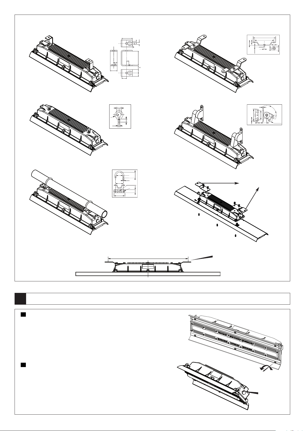
ccesso
F
ixin
ires d
g
accesso
e fixatio
ries (m
n
(m
m
)
m
)
FESBA
FESBS
FEFBZ
FEFBS
Chaîne de sécurité : en option
Safety chain : optional
FERBM8Z
FEHC49Z (42 à/to 49mm)
FEHC49S (42 à/to 49mm)
FEHC60Z (60mm)
FEHC60ZS(60mm)
4 FEET RETRO FIT BRACKETS
FEHBA
FEHBS
4 Feet retro fit Brackets
Ø 8 ,5
MO NTA GE / DÉM ON TAG E - ASSEMBLY / DI SA SS EM BLY
4
FR
Pour raccorder le câble d’alimentation, ouvrir le boîtier en dévissant les 6 vis du bas comme le
Fig. 1
montre la Fig. 1.
Tenir le réflecteur équipé de LED car il descend en s’ouvrant quand les 6 vis sont toutes sorties du
boîtier.
Ies vis sont imperdables et ne peuvent donc pas tomber du réflecteur.
Le mécanisme d’articulation assure la suspension du réflecteur LED après rotation (Fig. 2).
Raccorder les conducteurs au bornier, s’assurer que les fils sont bien fixés et que les vis des
bornes sont serrées.
Fermer le réflecteur LED et serrer les vis à un couple de 2,6 ± 5% Nm.
GB
To connect field wire open the housing by unscrewing the 6 bottom screws as shown in Fig-1.
Hold the LED array part to avoid any injury as it moves down for opening when all the 6 screws are
disengaged from the housing.
Vis - Screws
The screws have a captive feature; hence will not fallout from the part.
The hinge mechanism will take care of the hanging of the LED array mounted part (Fig-2).
Connect field wires to terminal block and ensure that the wire is secured and terminal screws are
tightened.
Close the LED array part and tighten the screws to a torque of 2.6 ±5% N-m.
2/3
Fig. 2
Charnière
Hinge
 Loading...