

Class I, Div. 1 and 2
Groups B, C, D
Class II, Div. 1 and 2
Groups F, G
Class III
Type 3R
NEMA 7BCD, 9F*G
300880-6
INSTRUCTION SHEET
U.S. Patent No. 3,735,078
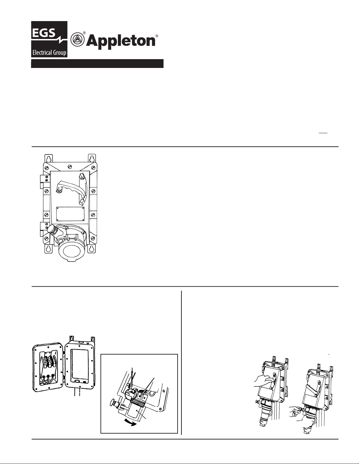
EBR Receptacle Enclosure:
Explosion-Proof, Dust-lgnition-Proof.
Weatherproof Spring Cover—30, 60 and 100 Amps at 600V A.C. Max.
Interlocked Circuit Breaker Safety Construction. Grounding thru Extra Pole and Shell
*CAUTION: To prevent Ignition of hazardous atmospheres, do not use in Class II,
Group F locations that contain electrically conductive dusts. Most coal dusts are not
electrically conductive.
I. TO DISASSEMBLE RECEPTACLE INTERIOR
1. Remove polarizing screw and washer.
2. Rotate terminal holder counter-clockwise.
II. TO CONNECT CONDUCTORS TO RECEPTACLE INTERIOR
1. Strip insulation from ends of individual conductors.
2. Loosen screws in pressure connectors and slide prepared ends of conductors into
the connectors, observing proper polarity. Tighten screws.
III. TO REASSEMBLE RECEPTACLE INTERIOR
1.Insert Terminal Holder and turn clockwise until front end is approximately 1/4” inside
of casting surface. Recessed radial depression in Terminal Holder must be lined up
with polarizing washer/locator. Replace screw through the ground strip.
IV. POLARITY AND PHASE ROTATION
1. ACP, CPH Plugs and EBR Receptacle are polarized so that the plug will enter the
1-1/2” threaded conduit
openings- one in top and
two in bottom
receptacle only one way.
Solderless lugs are provided for line connections
and receptacle is prewired to the load side of
breaker. Cover-mounted components leave entire
enclosure space free for pulling of line conductors
and wiring.
POLARIZED SCREW
AND WASHER
PRESSURE
CONNECTORS
SCREW
TERMINAL
HOLDER
Plug is mechanically locked in receptacle when circuit
breaker is ON. Design provides interlocked connect and
disconnect operation as well as short circuit and thermal
time delay overload protection. Breaker operating handle
can be padlocked in either “ON” or “OFF” position and is
trip-free.
Enclosure has 3/4” threaded openings top and bottom
for installation of UL Listed drain and breather. Reducers
are suitable for Class
I, Groups B, C and D,
Class II, Groups F and
G when installed such
that at least fi ve full
threads are engaged.
Unused openings must
be plugged with factory supplied plugs.
EGS Electrical Group • 800-621-1506 • www.appletonelec.com Rev. A 06/21/2007 Page 1
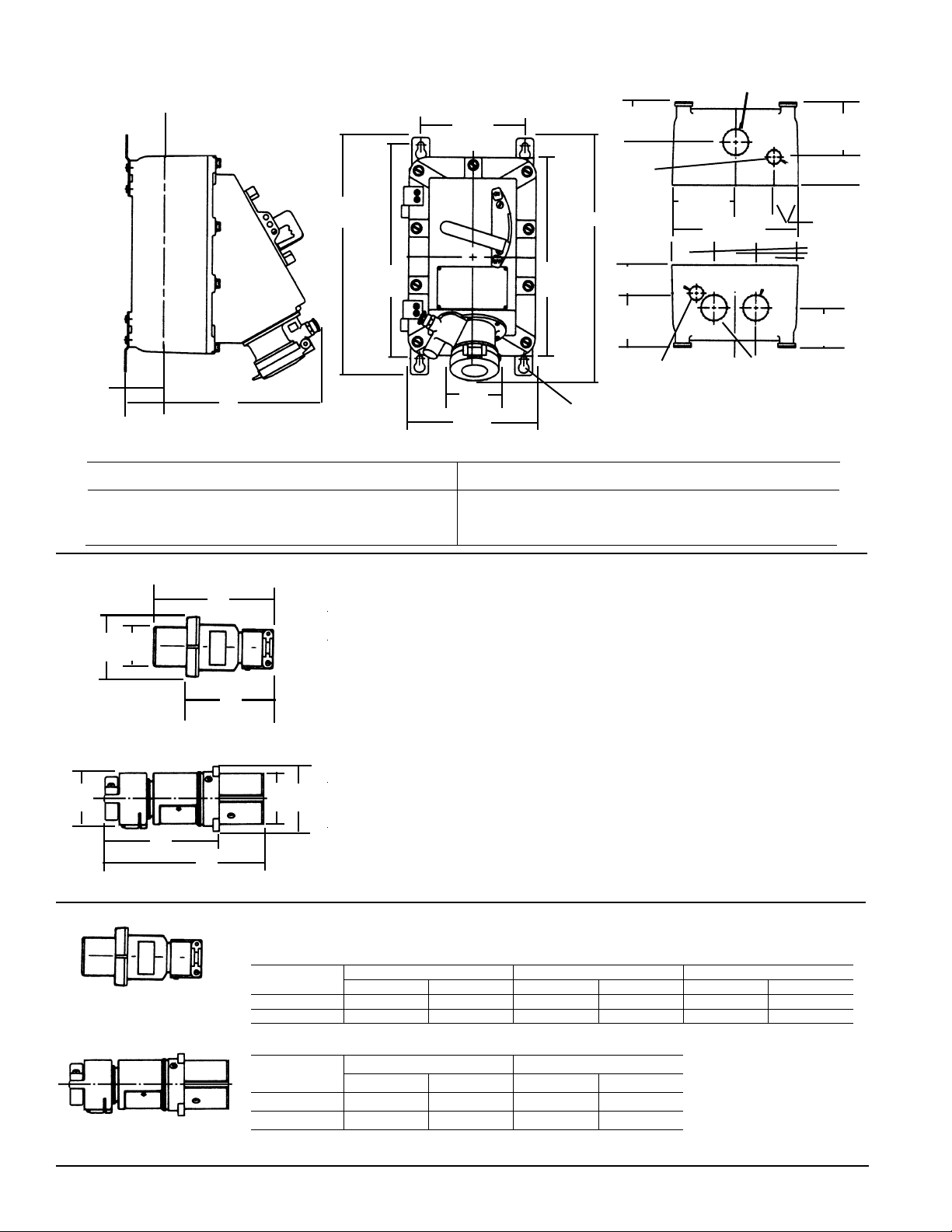
Dimensions of EBR Inter-Interlock Circuit Breaker Receptacles
C/L OF CONDUIT OPENINGS
7.44”
CONDUIT OPENINGS
TAPPED 1-1/2”
16.69”
42.4 CM
15.13”
38.4 CM
18.9 CM
14.06”
35.7 CM
B
TOP VIEW CONDUIT OPENING
1 1/2 - 11 1/2 NPT
2.63”
6.7 CM
3/4 - 14
NPT
4.50”
11.4 CM
9.00”
22.9 CM
2.00”5.1
CM
3.81”
9.7 CM
3.81”
9.7 CM
2.00”
5.1 CM
1.75”
45 CM
3.00”
7.6 CM
2.63”
8.7 CM
TWO THREADED 1 1/2
CONDUIT OPENINGS IN BOTTOM
BOTTOM VIEW
CONDUIT OPENING
2.75”
7.0 CM
A
C/L OF CONDUIT OPENINGS
3.0”
76 CM
9.06”
23.0 CM
3/4 - 14
NPT
MOUNTING HOLES
FOR 3/8” DIA. BOLTS
30 Amp 60 Amp 100 Amp 30 Amp 60 Amp 100 Amp
A 14.25” 14.25” 14.69” B 16.13” 17.69” 18.38”
(36.2cm) (36.2cm) (37.3cm) (41.0cm) (44.9cm) (46.7cm)
Dimensions in Inches
A
ACP Plugs for EBR Receptacles
No. Poles A B C D
C
D
30 Amp 2, 3, 4 6.00 4.75 3.13 1.86
60 Amp 2, 3 7 81 4.94 3.50 2.23
60 Amp 4 7.81 4.94 3.81 2.55
B
100 Amp 2, 3 10.50 6.63 4.00 2.47
100 Amp 4 10.50 6.63 4.25 2.72
CPH Plugs for EBR Receptacles
D
C
E
A
Max.
B
Amps. Wire/Pole A B C D E
30 2W, 3P; 3W, 4P 6.13 2.38 1.86 1.81 4.44
60 2W, 3P 8.44 3.06 2.23 3.31 5.69
60 W, 4P 8.44 3.06 2.55 3.31 5.69
ACP PLUG
CPH PLUG
Receptacle enclosure is for use with Listed Appleton plugs suitable for hazardous locations as
indicated below.
ACP Plugs for EBR Receptacles
Cable Dia.
(In.)
.390 to 1.375 ACP3023BC ACP3034BC ACP6023BC ACP6034BC --------- --------.875 to 1.906 --------- --------- --------- --------- ACP1023CD ACP1034CD
CPH Plugs for EBR Receptacles
Cable Dia.
(In.)
.500 to .875 CPH3023B CPH3034B --------- ---------
.390 to 1.375 --------- --------- CPH6023BC CPH6034BC
30 Amp 60 Amp 100 Amp
2W, 3P 3W, 4P 2W, 3P 3W, 4P 2W, 3P 3W, 4P
30 Amp 60 Amp
2W, 3P 3W, 4P 2W, 3P 3W, 4P
EGS Electrical Group • 800-621-1506 • www.appletonelec.comPage 2 300880-6 Rev. A 06/21/2007
 Loading...