


EGS Electrical Group • 7770 N. Frontage Road • Skokie, Illinois 60077
Rev. C 12/20/99 Page 1
650167-002
INSTRUCTION SHEET
BEAM-MASTER INSTALLATION / INSTRUCTION SHEET
IMPORTANT: To obtain full range of vertical aiming angles
(From NADIR to 90°), trunnion must be horizontal.
1. Cross Arm Bracket catalog number
G-AM-8-CA
• Use two 1/2" x 1-1/4" hex head bolts, and
lockwashers provided to attach trunnion to
bracket (see Figure 1).
• Next, attach Cross Arm Bracket to cross arm.
Hardware is not provided.
2. Pole Top Slipfitter catalog number
G-AM-8-SF
• Use two 1/2" x 1-1/4" hex head bolts provided,
attach trunnion to pipe slip fitter.
• Position slip fitter over top of pipe and secure
with four 3/8" set bolts.
3. Pipe Wall Bracket catalog number
G-AM-8-WB
• Attach fixture trunnion to cross arm bracket
G-AM-8-CA, use one 3/4" x 1-1/4" hex head
bolt and one 3/8" x 1" bolt to attach cross arm
bracket to top of pipe/wall bracket.
(See Figure 1).
WARNING:
Make certain power is off before starting installation
or any maintenance.
CAUTION: This fixture is designed for permanent installation
in ordinary (Non-Hazardous) or wet locations in accordance
with the National Electrical Code and all applicable local codes.
• Do not use in areas of limited ventilation or in high ambient
enclosures.
• The lamp and fixture operate at high temperatures, contact
with combustible material can cause fire and personal contact
can cause severe burns.
G-AM-8-CA
G-AM-8-WB
G-AM-8-SF
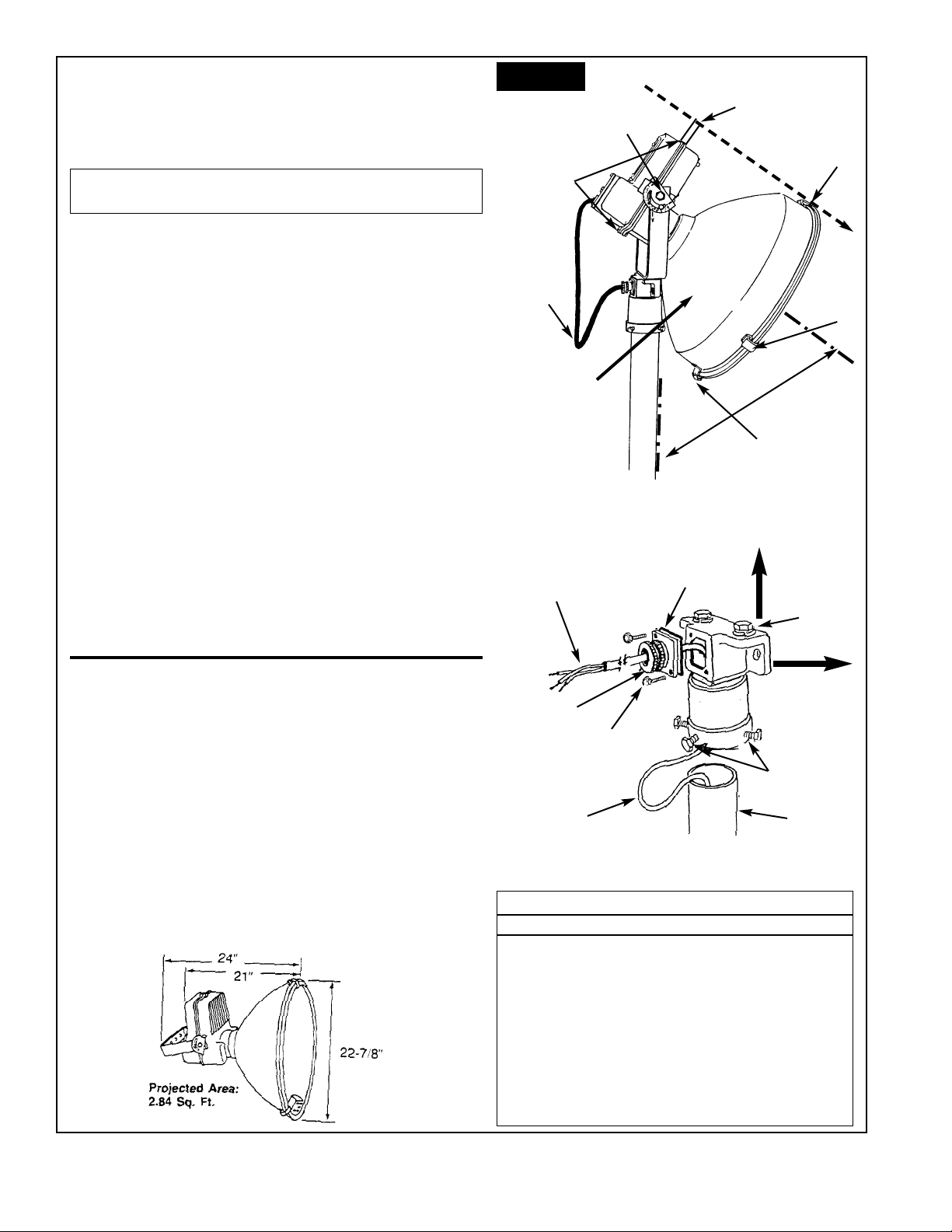
WIRING:
• Use 14/3, 90C, 600 volt cable for connection to supply.
• Sufficient cable must be allowed between fixture and junction
box to permit rotation of the fixture through its entire range of
rotation.
1. Loosen four screws "A" and remove wiring cover "B".
2. Loosen bushing clamp Plate "C" and feed supply cable thru
the bushing. Tighten bushing clamp plate.
3. Connect power leads to ballast primary leads in accordance
with N.E.C. and local codes.
4. CAUTION: Cap all unused power leads on multi-tap
ballasts.
5. Connect ground leads to green lead, provided in fixture. Do
Not use pole as ground.
6. Replace wire cover, NOTE: Make sure gasket is in proper
place.
7. In high humidity areas; use a punch to knock-out weep hole
in lower ballast half of housing.
VERTICAL: Using Protractor
•For vertical aiming using protractor supplied with fixture.
• First determine the vertical aiming angle from NADIR.
(From the lighting layout).
• Then depending on trunnion position follow these steps:
(Step 1 Horizontal - Step 2 Vertical)
1. For horizontally mounted trunnion.
NOTE: For greatest accuracy, trunnion must be level.
A. Loosen aiming bolt "G" and trunnion/fixture bolt "D"
rotate protractor "E" counter-clockwise until tab hits housing.
B. Determine aiming angle from layout and add 90° to that
angle (Example: Aiming angle from layout - 50° add 90° so
that result is 140°). ( Continued on page 2 )
AIMING: By Sighting
• For Horizontal aiming,
loosen bolt top or bolts holding pipe fitter, wall fitter or
cross arm bracket and rotate
floodlight to desired direction.
• For Vertical aiming, by
sight, Loosen top screw "J"
and mount aiming bar "H" in
vertical position and tighten
screw.
• Loosen aiming bolt "G" and
trunnion Bolts "D" sight
through notch in aiming latch
"F" at top of reflector with
target.
• Tighten trunnion bolts "D"
and then position tab on
Protractor index "E" against housing and tighten aiming bolt "G".
AIMING
BAR H
AIMING
SCREW J
AIMING
LATCH F
AIMING ANGLE
G-AM-8-WB
WALL
BRACKET
G-AM-8-CA
CROSS ARM
BRACKET
CROSS
ARM BOLT
TRUNNION
V - MARK
TA B
PROTRACTOR
JUNCTION
BOX
COVER - B
BUSHING
CLAMP
PLATE - C
COVER
SCREWS - A
AIMING
BOLT G
TRUNNION
BOLT D
FIGURE 1
EGS Electrical Group • 7770 N. Frontage Road • Skokie, Illinois 60077
Page 2
650167-002 Rev. C 12/20/99
C. While holding protractor tab against housing, rotate fixture
until desired angle. (Eg 140°) is at the "V" alignment mark on
trunnion bracket.
2.For Vertical mounted trunnion.
FOLLOW SAME PROCEDURE AS ABOVE EXCEPT:
• Do not add 90° to desired aiming angle.
SERVICE AND LAMPING
1. Loosen aiming bolt "D" and rotate fixture until glass lens cover
is in the straight up position.
• Tighten bolts "D" to lock fixture in this maintenance position.
2. Release three spring latches "E" and open glass lens cover
assembly for relamping and cleaning.
• To maintain lighting performance, the glass cover and inside
reflector should be cleaned periodically.
• To clean, wipe reflector and glass lens cover with a soft clean
damp cloth. If this is not sufficient, use a mild liquid cleaner.
• Do Not Use strong alkaline or acid cleaners, they may damage
reflector finish.
3. Install lamp in socket.
• Check nameplate for correct lamp type and wattage.
• Close cover assembly and secure the three latches "E" .
BALLAST SERVICE
1. Loosen aiming bolt "D" and rotate fixture until glass lens cover
is in the downward position.
2. Loosen two screws "J" and open ballast housing.
• Capacitor and ballast are only resting in stationary half of fixture.
3. Perform required service and close housing.
CAUTION
• Ensure that gasket around perimeter of housing is intact before
tightening screws.
• Ensure that wires will not be pinched when closing cover.
AIMING
BAR H
BALLAST
HOUSING
SCREWS
(2) J
DRIP
LOOP
HINGE
60° MIN.
AIMING
BOLT D
AIMING
LATCH F
SPRING
LATCH E
REFLECTOR
TOUCHES
POLE AT 60°
PULL 10" AND ENOUGH
CABLE FOR DRIP LOOP
IN FIXTURE WIRING
APPLICATION
VERTICAL
MOUNTING
HORIZONTAL
MOUNTING
PRESSURE
PLATE WITH
GASKET
CORD GRIP
1
3
4
#14-3, 90C, 600 V
CABLE FOR
CONNECTION TO
SUPPLY
POLE
SLIPFITTER INSTRUCTIONS
NOTE: Flexible cord or cable shall be type SOWA or SOOWA and
have a temperature rating as indicated on the product nameplate.
Cord should have a diameter between 0.5" and 0.625". Cords
outside of this range may prevent the proper functioning of the
clamp and result in water entry.
1. Loosen two screws on pressure plate for cable entrance.
2. Feed pole and bracket cable through cable entrance (#14 AWG
cable).
• Leave at least 10" of slack to make connections inside fixtures.
• Tighten pressure plate.
3. Mount slipfitter onto pole and tighten (4) mounting bolts.
4. Remove mounting bolt and place through center hole of yoke on
fixture.
• Mount fixture to slipfitter and secure mounting bolt tightly.
FIGURE 2
REPLACEMENT PARTS LIST
ITEM PART NUMBER
Glass Lens Cover Assembly 59566943001
Bushing Cord Entrance 59080816001
Clamp-Cord Bushing 59080820001
Socket 59759485005
Tr unnion 59607566001
Plate Wiring Access 59766024004
Lamp Stabilizer Spring 59766038001
Wire Insulator 59080540009
Gasket Reflector 59765973001
Plate Index 59765898002
Aiming Bar 59601297001
Reflector Housing Heavy Duty 59766292002
WARNING: Aiming angles of less than 60° are not possible with
a vertically mounted trunnion. See Figure 2.
 Loading...