

Appleton Instruction Sheet: Appleton™ A-51 LED Series Lighting Fixture for Groups A, B, C, D, 650592-000 Manuals & Guides
650592-000
INSTRUCTION SHEET
Installation and Maintenance Instructions for the
Appleton™ AA-51 LED Series Lighting Fixture
FOR PROPER AND SAFE INSTALLATION OF THIS PRODUCT PLEASE READ THE FOLLOWING INSTRUCTIONS
AND KEEP THIS MANUAL FOR FUTURE REFERENCE.
AA-51 LED Series lighting fixtures
for Hazardous Location
Class I, Div. 1, Groups A, B, C, D
Suitable for Group A, when used with Pendant Mount Only
Class II, Div. 1, Groups F and G
Class III
WARNING GENERAL
1. DO NOT MODIFY UNIT IN ANY WAY. Modication
may affect safety and reliability.
2. Improper use or failure to follow these instructions
could result in serious injury or property damage.
3. Operator should be instructed in the safe and
proper usage and maintenance of this product.
WARNING ELECTRICAL
1. Disconnect electrical power before installation,
adjustment and maintenance.
2. DO NOT overload; the amperage and voltage indicated
on the nameplate must not be exceeded.
3. Check continuity before connecting electrical power.
4. All installations must comply with applicable local
and/or National Electrical Code®.
5. Before installing check xture unit nameplate and
carton labels to be sure you have correct xture and
mounting hood. Circuit must be deactivated before
installing xture.
CAUTION GENERAL
1. All AA-51 LED Series Fixtures are to be mounted
vertically with globe facing down.
The xture unit MUST BE installed with one of the
following mounting hoods for safe operation. Failure to
use fixture unit with one of the following mounting hoods
voids warranty as well as the UL Listing and creates the
risk of re or explosion.
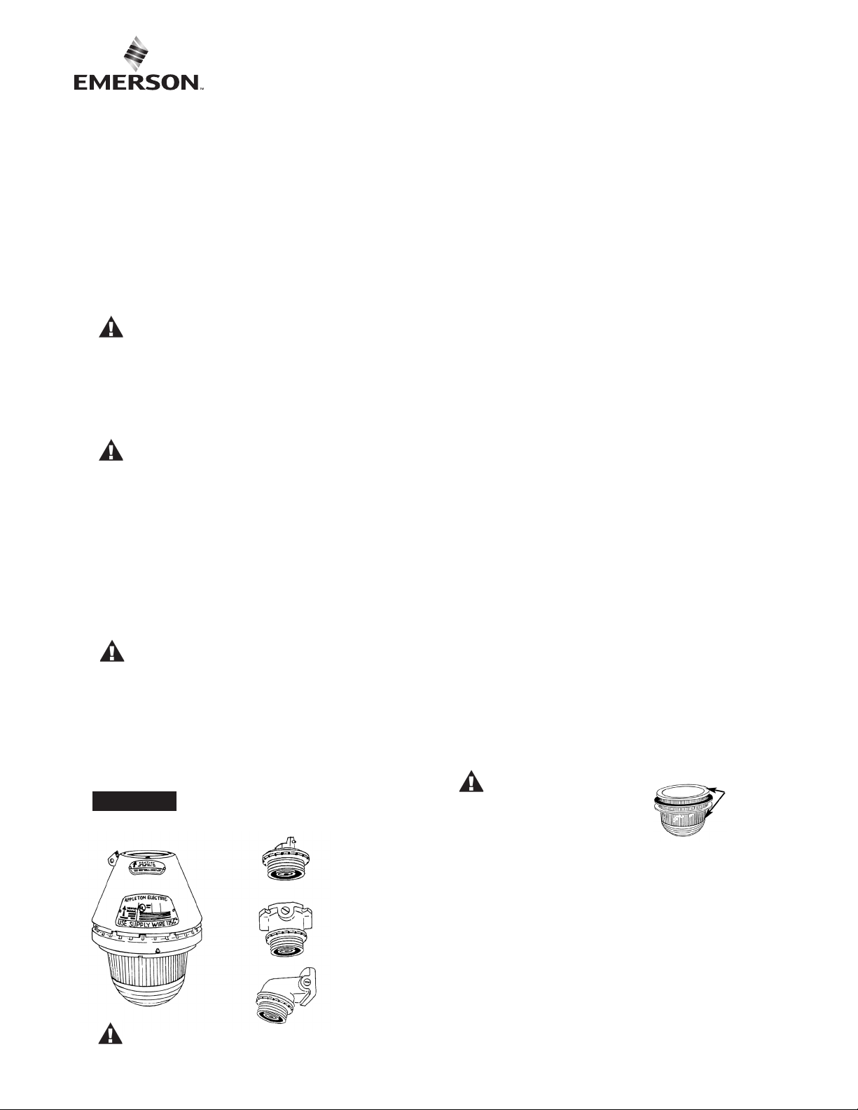
FIGURE 1
The AA-51 fixture MUST BE installed with:
AAP-50, AAP-75,
AEP-50, AEP-75
Pendant Hood - ONLY
*Group A with this hood.
(One hub, rigid or flexible mounting)
AAC-50, AAC-75,
AEC-50, AEC-75
Ceiling Hood
(Four hubs, three close-up plugs)
AASB-50, AASB-75,
AESB-50, AESB-75
Short Wall Bracket Hood
(Two hubs, one close-up plug)
FIXTURE INSTALLATION INSTRUCTIONS
Use the installation drawing as a guide. Install mounting
hood rst as all wiring connections are made in the
mounting hood. The fixture unit requires no internal
wiring connections.
1. Remove the connection block (VPT-7) from the
mounting hood by loosening (but not removing) the two
Phillips head screws. Turn connection block
counter-clockwise to remove.
2. When using ceiling (AAC- ) or short bracket (AASB-),
mounting hoods, threaded adapter (59064050000) can
be removed by lifting gasket (59064034000) to access
set screw.
• Loosen set screw and turn adapter
counter-clockwise for easier access to junction box.
3. Install mounting hood to conduit system (and/or
wall or ceiling). If using pendant, secure the hood to
the conduit system with the set screw.
4. Pull supply wires from the conduit into the junction box.
• Use supply wire rated 110°C minimum.
5. Secure threaded adapter (where applicable) to junction
box and tighten all set screws. Make connection of
supply wires to the VPT-7 connection block by
attaching “HOT” voltage lead to the black wire and
common “neutral” lead to the white wire on the
connection block.
6. Secure VPT-7 connection block to threaded adapter or
mounting hood by slipping over Phillips head screws;
turning clockwise and tightening screws.
7. Inspect threads of mounting hoods and of the xture
unit to be sure they are clean and free of damage.
Inspect globe for any chips, scratches or cracks.
CAUTION GENERAL
Chipped, scratched or cracked
globes will fail. Replace any
such defective lamp housing.
8. Thread the xture unit into mating threads of mounting
hood until tight against gasket of mounting hood.
Locking spring of xture unit should engage with
notches on mounting hood.
9. Install guard and/or reector if desired. Check tightness
of set screws and all threaded joints. Activate supply
circuit to test xture.
MUST BE
FREE OF
CHIPS OR
CRACKS
IMPORTANT: Remove all unused conduit plugs
and reinstall with pipe sealant.
650592-000 Rev. B 07/17/18 • Page 1 of 8Appleton • 1.800.621.1506 • www.appletonelec.com
NOTE: All installations must comply with applicable local and/or National Electrical Code.
CAUTION:
CAUTION: All AA-51 LED series fixtures are to be mounted vertically with globe facing down.
Disconnect supply circuit before opening or relamping fixture.
MAINTENANCE DATA
• To maintain maximum light output from this xture, it should be cleaned periodically as follows:
1. Alkaline or acidic cleaners will attack the protective coating of epoxy on the xture and should not be used.
The aluminum exterior of this fixture should be cleaned only with a mild soap or cleaner, and should
be rinsed with water immediately.
This will allow the epoxy to protect the xture from corrosive elements in the atmosphere and result in longer
xture life.
2. The glass globe should be cleaned using a soft cloth and a non-abrasive cleaner. The globe should be
regularly inspected for scratches or chips. If the globe is scratched or chipped, it must be replaced.
3. The porcelain enamel reector may be cleaned with any non-abrasive detergent or glass cleaner.
• These periodic cleaning procedures are important to prevent the accumulation of dust and dirt which
will impair the light output of the xture.
• When removing and repairing xture, lubricate threads only with Appleton TLC-3 conductive, high
temperature lubricant. This should only be necessary if threads are no longer coated with the blue or
black color of the TLC-3 dry lm Teon® lubricant.
OPERATIONAL DATA
• The xture must be operated in an environment that does not exceed 55°C.
• The xture may be operated on AC power only up to 277 VAC and 300 VDC.
• Use supply wire rated 110°C minimum.
WARNING
• To reduce the risk of fire or explosion, do not install where the operating temperature exceeds
ignition temperature of hazardous atmospheres.
• Refer to the nameplate on the fixture for maximum operating temperature and for proper
fixture classification.
Teon® is a registered trademark of E. I. du Pont de Nemours and Company.
650592-000 Rev. B 07/17/18 • Page 2 of 8Appleton • 1.800.621.1506 • www.appletonelec.com
SHORT BRACKET INSTALLATION
1. Remove threaded adapter from junction box for
easier access to conduit system.
2. Remove VPT-7 Connection Block from threaded
adapter.Pull supply wire (110°C minimum) into
junction box.
3. Replace threaded adapter and secure set screw.
4. Connect supply wires to appropriate “black” wire
and “white” wire on VPT-7 block per installation
instructions.
5. Push VPT-7 connector block into place and tighten
screws. Install xture unit.
• Remove unused conduit plug and reinstall
with pipe sealant.
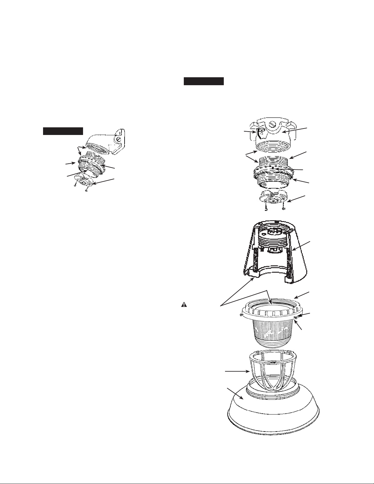
FIGURE 3
AA-51 LED FIXTURE SHOWN WITH
CEILING MOUNTING HOOD
FIGURE 2
TLC-3 LUBRICANT
SHOULD BE APPLIED
TO ALL THREADS
SET SCREW
GROUNDING
SCREW
AASB-50/75
15° SHORT
BRACKET
59064050000
THREADED ADAPTER
VPT-7 CONNECTOR BLOCK
SCREW #8 -32 x 1/2" PH. HD.
GREEN GROUNDING SCREW
TLC-3 LUBRICANT
BOTTOM LOCKING
SPRING WITH SCREW
#8-32 x 1/4" RD. HD.
JUNCTION BOX
Four hubs and
three close-up plugs
59064050000
THREADED ADAPTER
SLOTTED SET SCREW
1/4" - 20 x 3/8"
590640849
FIBER GASKET
VPT-7
CONNECTOR BLOCK
SCREWS (2)
#8 -32 x 1/2" PH. HD.
FIXTURE BODY
TLC-3 LUBRICANT
IMPORTANT NOTE
ALL GRIME AND GRIT MUST BE
REMOVED FROM GROUND
SURFACES OF FIXTURE BODY AND
GLOBE CONTACT POINTS.
ALSO APPLY TLC-3 LUBRICANT
TO GLOBE RING THREADS.
AAGUA-15
ALUMINUM GUARD
AARW-15ST
STANDARD PORCELAIN REFLECTOR
REFLECTOR MOUNTING
SCREWS (3)
# 8-32 x 3/8" RD. HD.
GLOBE AND RING ASSEMBLY
AAGUA-15
650592-000 Rev. B 07/17/18 • Page 3 of 8Appleton • 1.800.621.1506 • www.appletonelec.com
 Loading...