

Page 1
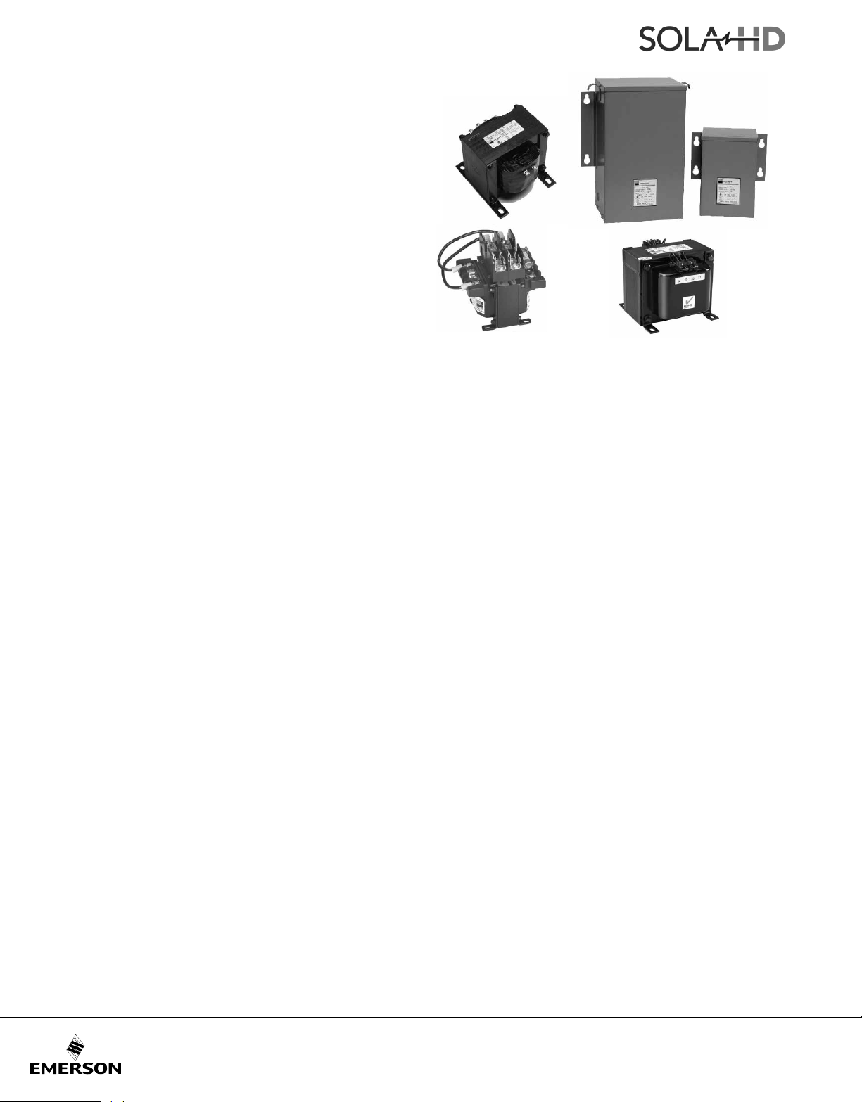
Industrial Control Transformers
© January 2017
Design Choices
SolaHD offers a broad range of industrial control solutions
for the most demanding industrial applications. Our products
exceed NEMA ratings for inrush and regulation to ensure
control systems are powered correctly. Electromagnetic
control components demand inrush currents up to 10
times the transformer’s nominal rating. While this inrush is
occurring, the output side of the transformer must not fall
below 85% of nominal as specied by NEMA ST-1, Part 4.
Using a transformer that does not meet these ratings may
cause erroneous shutdowns of downstream processes.
To meet your complete control needs, SolaHD's four series
of control transformers, all of which exceed the NEMA
standards. The Selection Chart can be used to identify the
appropriate transformer for your application.
The SBE series is available from 50 - 5000 VA, 55°C rise
and features copper windings and encapsulation (through
1000 VA) for longer life and protection from the environment.
This low temperature performance can mean smaller cabinet
size or longer life for any electronic components that may
be nearby.
The SMT series are 115°C rise, aluminum wound and for
applications where good voltage regulation and higher
power capacities (1000-5000 VA) are required.
A. Sealed VA - Total steady state sealed VA is the
volt-amperes that the transformer must deliver to
the load circuit for an extended period of time.
B. Inrush VA - Total inrush VA is the volt-amperes that the
transformer must deliver upon initial energization of the
control circuit. Energization of electromagnetic devices
takes 30-50 milliseconds. During this inrush period the
electromagnetic control devices draw many times normal
current – 3-10 times normal is typical.
The International series meets IEC requirements and IP20
(touch proof covers ordered separately for E models) for
European applications.
The HSZ series rounds out SolaHD’s line with an enclosed
series of control transformers from 1 - 10 kVA that feature
either a UL Listed Type 3R, 4, 4X or 12 enclosure.
This unique design, featuring copper windings and
encapsulated construction, can help system designers
meet harsher environmental standards or design for a safer
installation outside of a control cabinet. The HSZ series is for
applications where cost or heat issues make mounting the
transformer outside the control panel necessary.
SolaHD is pleased to offer custom transformers 1 kVA
and larger. If you can't nd what you are looking for here, we
are happy to provide a quote on a custom transformer if
available. Contact your local sales representative for more
information.
Sizing an Industrial Control Transformer
For proper transformer selection, three characteristics of
the load circuit must be determined in addition to the
minimum voltage required to operate the circuit. These
are total steady state (sealed) VA, total inrush VA, and inrush
load power factor.
C. Inrush Load Power Factor is difcult to determine without
detailed vector analysis of all the load components.
Generally such an analysis is not feasible, therefore, a
safe assumption is 40% power factor (PF). Until recently
20% PF was commonly used for transformer calculations,
however, tests conducted on major brands of control
devices indicate that 40% PF is a safer default
assumption.
Selection Steps
1. Determine the supply and load voltages. The supply
voltage is the available voltage to the control transformer.
The load voltage is the operating voltage of the devices
that will be connected to the transformer output.
2. Calculate the total sealed VA by adding the VA
requirements of all components that will be energized
together (timers, contactors, relays, solenoids, pilot
lamps, etc.). Sealed VA data is available from the control
device manufacturer.
3. Add the inrush VA of all components that will be
energized together. Be sure to include the sealed VA
of components that do not have an inrush, (lamps,
timers, etc.) as they present a load to the transformer
during maximum inrush.
184
Page 2
Industrial Control Transformers
© January 2017
4. Calculate selection inrush VA in one of the following
two ways:
A. Selection inrush VA =
(VA sealed)2 + (VA inrush)
√
2
Alternative Method
B. VA sealed + VA inrush = Selection inrush
Method B will result in a slightly oversized transformer.
5. If your line voltage varies 10% or more, contact Technical
Services for assistance.
6. Utilizing the regulation data chart below, select the
transformer VA needed for your application from the
“Transformer VA Rating” column. Check to be sure that
the nameplate VA rating exceeds the sealed VA of the
control circuit calculated in Step 1. If it does not, select a
larger transformer VA that exceeds the circuit sealed VA.
By following the above procedure, the secondary voltage
delivered by the transformer will be 90% of the nameplate
secondary voltage under maximum inrush conditions at
rated input voltage.
Now refer to the selection tables on the following pages
for the style you have chosen. Select your transformer
according to your required voltage and VA capacity.
Regulation Data – Inrush VA at 20% and 40% Power Factor
20% PF
1
Transformer
2
40% PF
VA Rating
2
Selection Inrush VA
Type SBE Type SMT
2
20% PF
294 207 N/A N/A 50
515 363 N/A N/A 75
696 490 N/A N/A 100
1362 959 N/A N/A 150
2131 1501 N/A N/A 200
2883 2031 N/A N/A 250
3608 2541 N/A N/A 300
4777 3364 N/A N/A 350
7601 5353 N/A N/A 500
12939 9112 N/A N/A 750
18703 13171 8277 5829 1000
23814 16066 17182 12100 1500
34586 24356 22834 16080 2000
45633 32770 34506 24300 3000
158000 111000 71284 50200 5000
1
Assuming the transformer is to deliver a minimum of 90% secondary
voltage during inrush conditions.
2
See C. Inrush Load Power Factor on page previous page.
40% PF
2
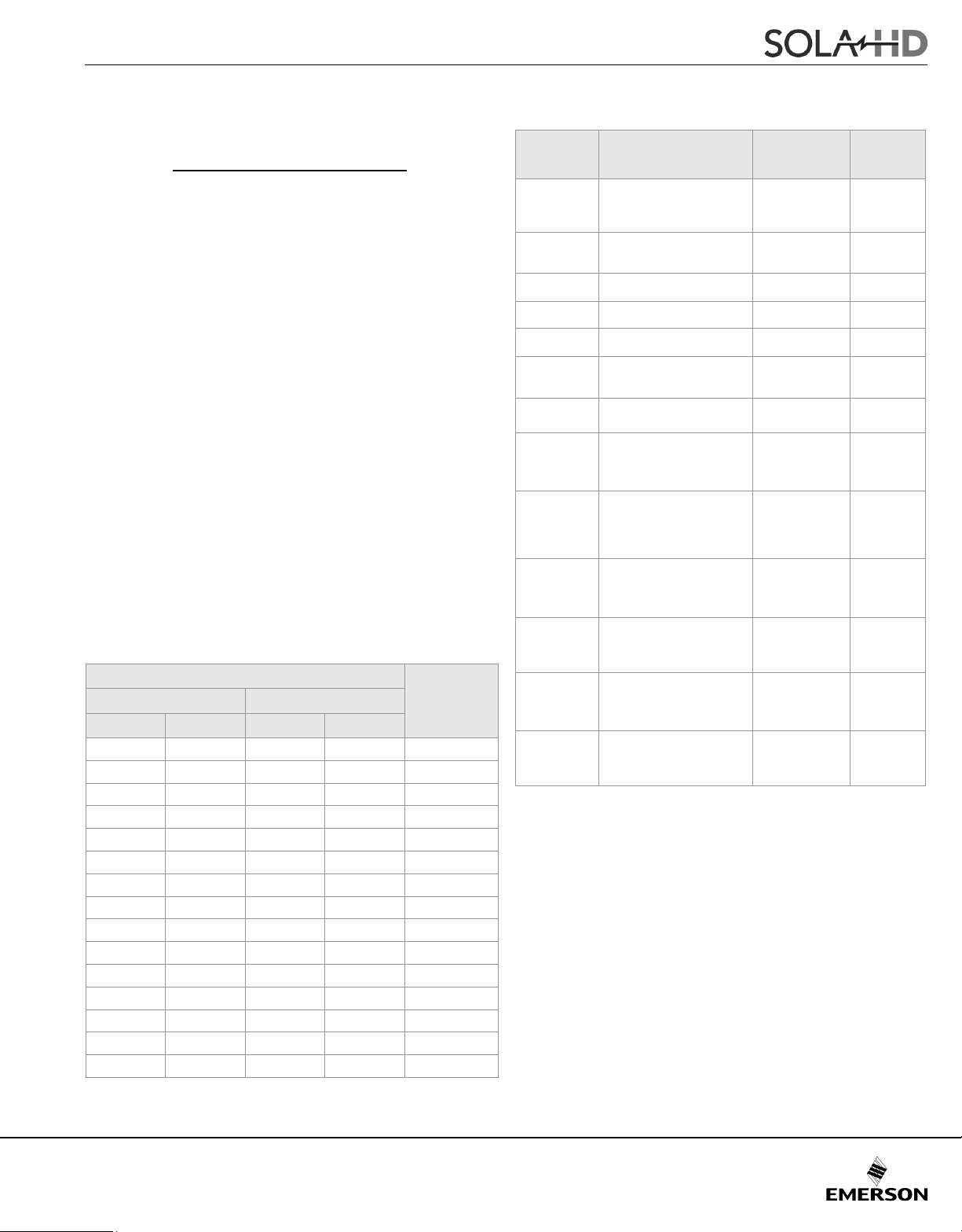
Chart A: Voltage Code Chart
Voltage Code Primary Voltage
240 x 480
None
A
D
E
JL
JN
R
TC
TE
TF
TH
MH
MC
Note: "—" indicated tap not used.
* 60 Hz only at 277, 575 or 600 V.
230 x 460
220 x 440
240/480/600
230/460/575
240 x 480 24 60
120 x 240 24 60
208/240/277 120/24 60
208/240/480/600
200/230/460/575
480 240 50/60
208/240/—
200/230/400
—/220/380
208/240/—
—/277/480
200/230/400
—/220/380
208/240/—/480/*600
200/230/400/460/*575
220/*277/380
240/—/480
230/400/460
220/380/440
208/240/—/480/600
200/230/400/460/575
—/220/380/440/550
208/240/—/480/600
200/230/400/460/575
—/220/380/440/550
Secondary
Voltage
120
115
110
120/99
115/95
120/24
115/23
120/ — /24
115/24/23
110/23/ —
24
24
24
23
120
115
110
120/240
115/230
110/220
120/240
115/230
110/220
120/ — /24
115/24/23
110/23/ —
Hertz
60
50/60
50/60
50/60
60
60
50/60
50/60
60
60
50/60
50/60
60
50/60
50/60
60
50/60
50/60
60
50/60
50/60
60
50/60
50/60
185
Page 3

Industrial Control Transformers
© January 2017
VA
INTERNATIONAL SBE SERIES ENCAPSULATED INTERNATIONAL SFP SERIES ENCAPSULATED
TC TE TF TH TH MH MC
Temp 55°C 80°C
50 E050TC E050TE E050TF E050TH
100 E100TC E100TE E100TF E100TH
150 E150TC E150TE E150TF E150TH
250 E250TC E250TE E250TF E250TH
500 E500TC E500TE E500TF E500TH
750 E750TF E750TH CE750MC
1000 CE1000TH CE1000MH CE1000MC
1500 CE1500TH CE1500MH CE1500MC
2000 CE2000TH CE2000MH
Choosing the Correct Series
The SBE series of industrial control transformers provide
voltage regulation which exceeds NEMA standards. They
have a 55°C rise and have copper windings and are 50/60
The International series have multiple voltage taps for easy
application. These units also meet IEC 61558-1, 61558-2-2
and are CE marked for easy export to European countries.
Hz rated. The SBE series can handle signicant inrush with a
minimal drop in output voltage.
The HSZ series is for applications where cost or heat
issues make mounting the transformer outside the control
The SMT series are 115°C rise, aluminum wound and are for
applications where good voltage regulation and higher power
capacities are required.
panel necessary. This series has 80°C rise and has
copper winding for industrial applications. These units are
enclosed with UL Listed/NEMA Type 3R enclosures. Also
available in UL Listed/NEMA Type 4, 4X and 12.
Selection Chart
VA
-- D E JL JN -- -- -- A R
Temp 55°C 115°C 80°C
50
75
100
150
200
250
300
350
500
750
1000
1500
2000
3000
5000
75000
100000
* Change HZxxxx to HZ12xxxx for Type 12 or 4 applications or HZ4Xxxxx for Type 4X applications.
E050 E050D E050E E050JL E050JN
E075 E075E
E100 E100D E100E E100JL E100JN
E150 E150E E150JN
E200 E200E
E250 E250D E250E E250JL E250JN
E300 E300E
E350 E350E
E500 E500D E500E E500JL E500JN
E750 E750E
E1000 T1000 HZ1000 HZ1000A HZ1000R
SBE ENCAPSULATED
SBE OPEN
(SZO)
Y1500 T1500 HZ1500 HZ1500A HZ1500R
Y2000 T2000 HZ2000 HZ2000A HZ2000R
Y3000 T3000 HZ3000 HZ3000A HZ3000R
Y5000 T5000 HZ5000 HZ5000A HZ5000R
SMT OPEN HSZ * TYPE 3R
HZ75000 HZ75000A HZ75000R
HZ10000 HZ10000A HZ10000R
Selection Chart - International Series
186
 Loading...