

Page 1
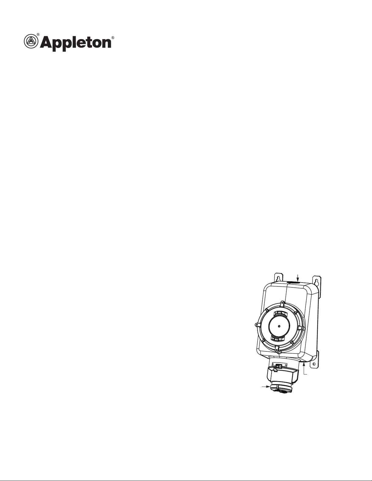
TOP
CONDUIT
ENTRY
SCREW COVER
ASSEMBLY
BOTTOM CONDUIT
ENTRY & DRAIN PLUG
303359 INSTRUCTION SHEET
Installation & Maintenance Instructions for FSQC 100 Ampere Receptacle
RETAIN THIS INSTRUCTION SHEET FOR FUTURE REFERENCE.
For safe installation and operation, please read these instructions carefully and with full understanding.
FSQC Series
Receptacle interlocked with switch for use in hazardous locations.
Compliance
UL Standards: 050E, 1010, 1203, 1682, 1686
CSA Standards: No. 30, C22.2 No.25, C22.2 No.159
Electrical Ratings
Maximum Voltage: 600 V ac at 60 Hz
Current: 100 Amperes
Configuration: 3W, 4P
Applications
• Designed to supply power to portable or xed electrical equipment such as motor generator units, welders, pumps,
compressors, and similar apparatuses.
• Ideal for use on shipping docks, ports, and other “Ship-to-Shore” applications.
• Suitable for use in locations where a weatherproof enclosure is required.
• Interlocked receptacle design provides use in hazardous locations and rough environments.
Features
• Rugged and Type 4X watertight enclosure and cover, sealed with an O-ring.
• Grounding Style—Style 2 receptacle ground through shell and extra pole.
Receptacle is dead front without plug engaged.
• Arcing Conned—Interlock receptacle design means that all electrical switching
is done with an internal switch. The plug cannot be engaged or disengaged with
the receptacle when the switch is “ON”.
• Positive Contact—Brass contacts have integral springs for positive, maintained,
electrical contact.
• Receptacle face enables the engagement of plugs for a weatherproof union.
• Positive Ground—Grounding terminal for Style 2 receptacle “makes rst,
breaks last”.
• Receptacle is designed so that it can only turn “ON” when the proper mating
plug is fully engaged and the pad locking collar is rotated. See Table 6 for a list
of the mating plugs.
• Receptacles come with a ip cover and a screw cover for protection against
environmental conditions.
• Cover cannot be removed when the switch is “ON”.
• P4 Option—Special polarization prevents plug insertion into a receptacle wired
for a different voltage.
• Style 2 interlocked receptacles are equipped with contacts designed to provide a safety polarization means called “controlled
length” contacts. This feature will not allow the plug grounding contact (Style 2) to touch an energized receptacle “line” contact
in the event the plug becomes damaged and/or loses its primary polarization means and/or is rotated into the incorrect position.
303359 Rev. D 05/13 • Page 1 of 12
Page 2

Product Safety Information
Signal Words Defined
DANGER indicates a hazardous situation which, if not avoided, will result in death or serious injury.
WARNING indicates a hazardous situation which, if not avoided, could result in death or serious injury.
CAUTION indicates a hazardous situation which, if not avoided, could result in minor or moderate injury.
NOTICE is used to address practices not related to physical injury.
Safety Instructions
!
WARNING—MODIFICATIONS
Do not modify these devices in anyway. Replace any missing or broken parts with proper Appleton replacement parts. Modication of
these devices or substitution of parts with non-standard parts may result in serious or fatal person injury from electrocution.
!
WARNING—PRODUCT DAMAGE
If any part of the receptacle appears to be missing, broken, or show signs of damage—discontinue use immediately! This condition
could cause serious or fatal personal injury due to electrocution and/or equipment damage. Repair with the proper replacement part(s)
before continuing service.
!
WARNING—ENVIRONMENTAL
To prevent ignition of hazardous atmospheres, do not use Class I, Group F locations that contain electrically conductive dusts.
!
WARNING—ELECTRICAL
Electrical power must be turned OFF before and during installation and maintenance. Failure to do so may result in serious or fatal
injuries due to electrocution.
!
WARNING—WIRING
Use only copper cable or wire per the National Electric Code (NEC) for the given ampere rating of the receptacle.
!
WARNING—WIRING
A wiring scheme must be followed so that the same color wire is always put into the same numbered contact opening in all plugs,
connectors, and receptacles in the system. This will help to eliminate possibilities for equipment damage and/or personal injuries due
to electrocution.
303359 Rev. D 05/13 • Page 2 of 12
Page 3
Drawings
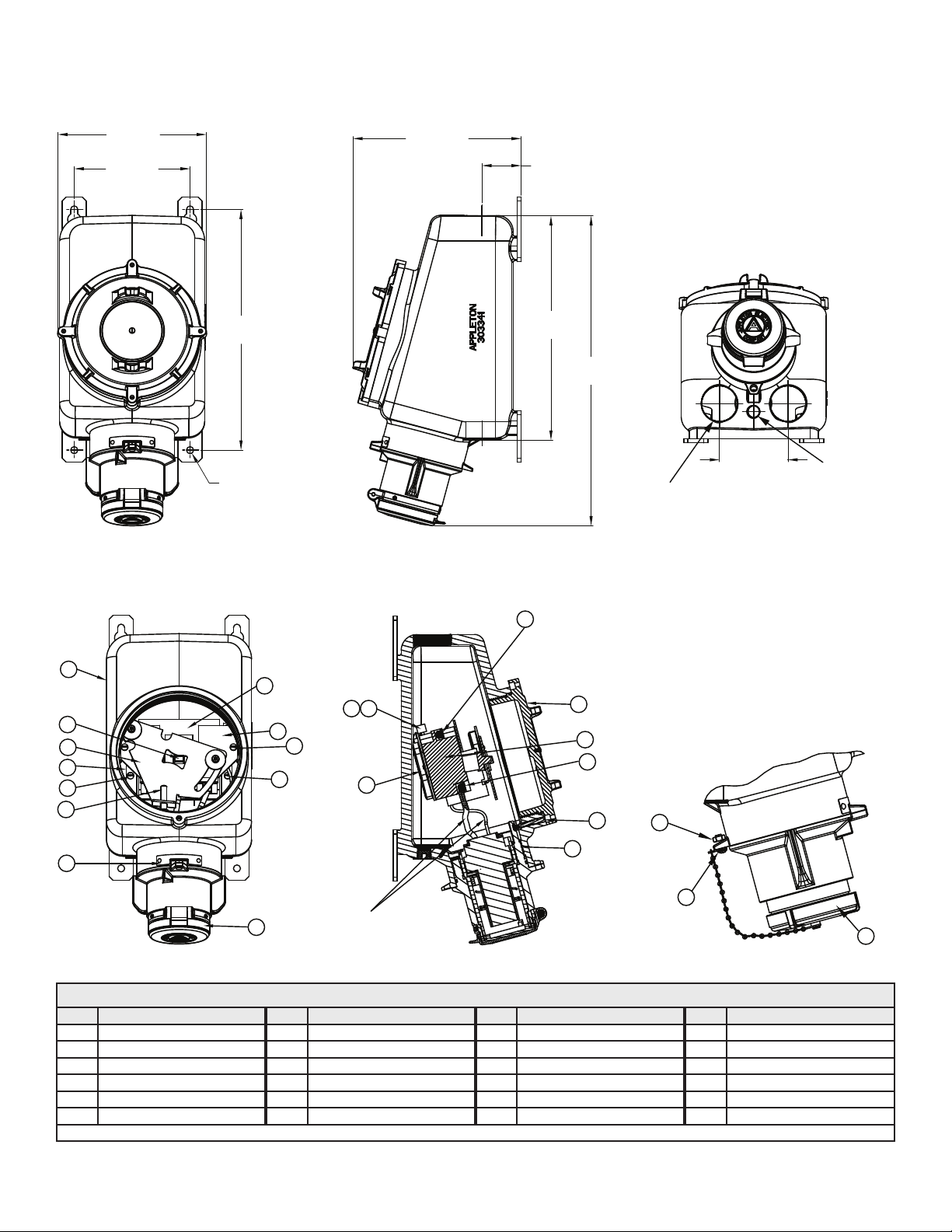
Figure 1: FSQC 100 A Dimensions (Shown with flip cover for maximum space consideration)
9.00"
22.86 CM
7.19"
18.26 CM
14.94"
37.95 CM
Ø 7/16 TYP.
10.44"
26.54 CM
2.44"
6.20 CM
13.92"
35.31 CM
19.22"
48.89 CM
10.79 CM
3 CONDUIT ENTRIES
SIZE 2-11 1/2 NPT
(1 AT TOP, 2 AT BOTTOM)
4.25"
1 DRAIN PLUG
SIZE 1/2-14 NPT
Figure 2: FSQC 100 A Details & Parts List
8
SWITCH TERMINAL
SCREWS FOR LINE
WIRE CONNECTION
5
16
17
7
14
12
13
11
10
20
15
19
1
18
24
FACTORY WIRED
Table 1: Parts List
Item # Part Description Item # Part Description Item # Part Description Item # Part Description
1 Receptacle Flip Cover* 7 Switch Toggle 13 Switch Base Plate Screws 19 Ground Wire
2 Enclosure Cover 8 Line Side Pressure Screws 14 Sliding Plate 20 Fixed Plate
3 Locking Screw 9 Load Side Pressure Screws 15 Fixed Plate Screw 21 Screw Cover Assembly*
4 Receptacle Housing Body 10 ON/OFF Nameplate 16 Clear Plastic Shield 22 Screw
5 Enclosure 11 Switch Actuator Stud 17 Ground Lug 23 Nut
6 Disconnect Switch 12 Switch Base Plate 18 Ground Lug Screw 24 Switch Mounting Screws
Choose Item Number 1 or 21 based on the application.
*
2
6
9
3
4
23
22
21
303359 Rev. D 05/13 • Page 3 of 12
Page 4

Installation
!
WARNING
Electrical power must be turned OFF before and during installation and maintenance. Failure to do so may result in serious or fatal
injuries due to electrocution.
!
CAUTION
Before starting the installation, ensure the receptacle assembly is suitable for the intended location according to the National Electrical
Code or Canadian Electrical Code. If the receptacle assembly is not suitable, serious damage and injuries may result. Owners are
responsible for damages or injuries if these rules are not followed.
Prepare the Mounting Position
1. The receptacle assembly must be mounted on four 13/32 inch or 3/8 inch steel, hex head bolts per ANSI B18.6.3 and securely
fastened to a wall, column, strut, or other vertical structure, in one plane, which is capable of supporting the receptacle and its
associated conduit and wiring.
NOTE: Bolts are not provided with the receptacle assembly.
2. Prepare the structure for mounting bolts by drilling, tapping, using securing nuts, or another method of providing thread anchors for
the bolts. See Figure 1 for the dimensions of the receptacle.
3. The bolts must be engaged at least ve full threads.
Mounting the Receptacle
!
WARNING
Before mounting the receptacle, ensure that the enclosed switch is in the “OFF” condition.
1. Place the receptacle assembly on the previously prepared mounting bolts, with the receptacle ip cover at the lower-most position.
Make sure that the bolt shanks are in the mounting holes. Tighten the bolts to 18 to 20 ft.- lb. torque.
Opening the Receptacle Cover
1. Referring to Figure 2, turn the cover locking screw (Item #3) clockwise (inwards) until it enters into the groove of the receptacle
housing body (Item #4). This makes the enclosure cover (Item #2) free for rotation and simultaneously locks the receptacle interior
rotation (also toggling of the switch).
2. Turn the enclosure cover counterclockwise (outward) to completely remove it from the enclosure.
3. After removal, we recommend that the enclosure cover be placed with the outer surface down, on a clean surface. Protect the
enclosure cover with a tarp or covering to ensure that it remains clean and functional.
Conduit Installation
!
CAUTION
Please note that all conduit entries must be used. Install sealing ttings within 18 inches of each conduit entry per the National Electrical
Code requirements.
1. Conduit entries of 2 inch NPT are provided on both the top and bottom of the enclosure (see Figure 1).
2. Make sure all conduit entries are clean and free of debris before installing the conduit and close-up plugs.
3. On all conduits, reducer bushings, and close-up plugs, grease must be used to completely seal out water.
NOTE: We recommend applying Appleton thread lubricant (part number TLC-3) on threads in three generous lines, running parallel
to the thread axis and spaced equidistant around the thread.
4. Conduits and close-up plugs must be turned in until snug and then 1/2 turn further with a wrench. Make sure any installed
breathers and drains are tightened in the same manner.
NOTE: Do not over-tighten, as damage to the housing threads or any reducer bushings may occur.
5. At this point, ensure that all threaded holes in the housing are closed (including openings for breathers and drains) to prevent entry
of rain, splashed water, and hose directed water, and also to comply with Class I and Class II hazardous location requirements.
303359 Rev. D 05/13 • Page 4 of 12
Page 5

Wiring
!
WARNING
Use copper conductors only, suitable for at least 75°C (167°F). Do not use aluminum wiring, as dangerous overheating and re may
result.
1. Feed the power supply wiring into the enclosure through the conduit entries (see Figure 1).
2. Strip the individual conductors per Table 2.
Table 2: Conductors
Ampere Rating Strip Length (in.) Wire Range (AWG) Torque Value (in.- lb.)
100 5/8 #2–1/0 50
3. Referring to Figure 2, remove the disconnect switch’s sliding and xed plates (Item #14 & #20) by removing the two screws (Item #15).
Lift the plates up and slide them away from the switch actuator stud (Item #11).
4. Remove the clear plastic shield (Item #16) by loosening (but not removing) its holding screws.
5. Connect wires to the proper terminals of the switch by loosening (but not removing) the line side pressure screws (Item #8). Insert
conductors, including all strand switch terminals, according to your established wiring scheme.
6. Connect the ground wire with the line ground lug (Item #17).
7. Tighten the screws with 40 in.- lb. torque.
8. Replace the clear plastic shield and plates by reversing Steps 3 and 4.
Electrical Testing
All wiring must be checked and tested to ensure that all circuits are according to plan and that there are no unwanted opens, shorts or
grounds.
Do not apply power until the following steps are completed:
1. Test to verify correct phasing and ground connections.
2. Test insulation resistance by meggering, high voltage, or hi-pot test to ensure that the system does not have any short circuits or
unwanted grounds.
Clean the Receptacle Cover & Enclosure
Before replacing or closing the receptacle cover, it is strongly recommended that all dirt, debris, and other foreign materials be
removed from the enclosure interior. This action should be taken to help keep the breathers and drains from being plugged by these
materials.
1. Make sure the enclosure top face is clean. Wipe it with a clean, dry cloth to remove any foreign materials.
2. Clean the mating surface of the receptacle cover in the same manner, while being careful not to damage the O-ring.
Close the Receptacle Cover
1. Apply a thin lm of conductive grease (Appleton part number TLC-3 is recommended) on the threads of the housing. The purpose of
this grease is to further ensure against water migration through the receptacle cover and housing joint. Grease should be reapplied
each time the receptacle cover is opened.
2. Place/afx the cleaned receptacle cover in the enclosure by turning it clockwise. Ensure that more than seven threads are engaged
and that the cover sits face-to-face with the enclosure.
3. Referring to Figure 2, align the cover locking screw (Item #3) with one of the nearest holes on the cover ange.
4. Turn the cover locking screw counterclockwise (outward) all the way. This will lock the cover in place and will release the receptacle
interior so that the switch can be operated.
303359 Rev. D 05/13 • Page 5 of 12
Page 6

Operation
Plugs
The FSQC receptacle is designed to accept the clamping rings of ACP plugs (see Table 3). Clamping rings t onto the receptacle to
form a watertight Type 4X assembly with plug-in use.
When the plug is withdrawn from the receptacle that has the ip cover option installed, the gasketed cover automatically closes tightly
against the receptacle opening, providing weatherproof Type 3R protection. When the plug is withdrawn from the receptacle that has
the screw cover option installed, the gasketed cover screws tightly against the receptacle opening, providing weathertight Type 4X
protection.
Table 3: ACP Plug for FSQC 100 A Receptacle
Cable Diameter (in.) Part Number Part Description
0.875–1.906 ACP1034CD 100 A—3W, 4P
NOTES:
• The Appleton FSQC receptacles and ACP plugs are UL Listed combinations.
• Receptacles with the P4 option have the interior rotated 22 1/2 degrees for special polarization applications. They are compatible
only with Appleton plugs with the P4 option.
Operating
1. Verify that the enclosed switch is in the “OFF” position. The “Arrow” on the receptacle collar should be in line with the “OFF”
marking on the nameplate.
2. Align and insert the mating plug fully inside the receptacle. Rotate the receptacle collar clockwise until the “Arrow” indicates “ON”.
The plug is now mechanically locked into the receptacle.
3. Tighten the clamping ring of the plug to the receptacle.
NOTES:
• To turn OFF, loosen the clamping ring and turn the padlock collar counterclockwise until it cannot go any further. The “Arrow”
should be in line with the “OFF” marking on the nameplate.
• A hole is provided in the receptacle collar and enclosure for the use of padlocks to “lockout” unauthorized movement of the plug
from the “OFF” position.
• The receptacle collar must be fully rotated ON/OFF as indicated on the nameplate to have the switch turn ON/OFF properly. This
can be checked by listening to the switch “click” during each ON/OFF cycle.
303359 Rev. D 05/13 • Page 6 of 12
Page 7

Maintenance
!
WARNING
Electrical power must be turned OFF before and during installation and maintenance. Failure to do so may result in serious or fatal
injuries due to electrocution.
The receptacle must be inspected regularly. Schedule of inspections is determined by frequency of use and environmental conditions.
We recommend that inspections be carried out at least once a year and that an electrical preventive maintenance program (e.g. National
Fire Protection Bulletin NFPA No. 70B) be followed in addition to the steps below.
During the inspections, perform the following steps:
1. Inspect/ensure that all conductor terminations are secure. Re-torque to values given previously in these instructions if necessary.
NOTE: Discoloration due to excessive heat is an indicator of possible problems and should be investigated and repaired as necessary.
2. Check grounding and bonding effectiveness/continuity. Re-torque connections to original values if necessary.
3. Check gaskets for damage and replace as necessary.
4. Inspect breathers and drains for proper function. Clean or replace as necessary.
5. Check all conduits and close-up plugs for tightness and re-torque as necessary.
6. Clean interior of all foreign materials.
7. Make sure all openings are closed.
8. Cover bolts must be tightened AND the cover locking screw engaged inside the cover.
9. Make sure the receptacle assembly nameplate remains clean and legible. Do not paint the nameplate.
NOTES:
• The receptacle insulator and contacts are not serviceable; consult with the factory.
303359 Rev. D 05/13 • Page 7 of 12
Page 8

Service
!
WARNING
Electrical power must be turned OFF before and during installation and maintenance. Failure to do so may result in serious or fatal
injuries due to electrocution.
!
WARNING
If any part of the receptacle appears to be missing, broken, or show signs of damage—discontinue use immediately! This condition
could cause serious or fatal personal injury due to electrocution and/or equipment damage. Repair with the proper replacement part(s)
before continuing service.
Disconnect Switch
Disconnect switches occasionally fail and need to be replaced. The disconnect switch used in this receptacle can be replaced with the
same type and brand as factory installed and will not affect the UL Listing.
To Replace the Disconnect Switch:
1. Referring to Figure 2, remove the switch actuator stud (Item #11) by unscrewing it.
2. Remove the disconnect switch’s sliding and xed plates (Item #14 & #20) by removing the two screws (Item #15).
3. Remove the clear plastic shield (Item #16) by loosening (but not removing) its holding screws.
4. Loosen the line and load side pressure screws (Item #8 & #9) and remove the line and load side wires from the disconnect switch (Item #6).
5. Remove the switch base plate (Item #12) by removing the switch base plate screws (Item #13).
6. Remove the disconnect switch from its base plate by taking out the switch mounting screws (Item #24). Remember the orientation
of the pointer on Interlock Sleeve with respect to the switch position. The pointer must indicate that the receptacle is “OFF” when
the disconnect switch is in the “OFF” position.
7. Replace the disconnect switch, with the same type as shown in Table 4, by reversing the steps above. Make sure to reconnect the
wires to the same locations as before disassembly.
Table 4: Disconnect Switch
Disconnect Switch Part Number
Appleton Cuttler-Hammer
Ampere Ratings Number of Poles Horsepower
59301020100 DS36U 100 A 3 75
8. Torque the switch mounting screws to 25 in.- lb. to fasten the disconnect switch onto the switch base plate. Assemble the switch
subassembly in the enclosure using the switch base plate screws with a torque of 25 in.- lb.
9. Torque the line and load pressure screws to 50 in.- lb. to hold the wires in place.
10. Conduct electrical tests. Refer to “Electrical Testing” on page 5 for details.
Terminal Block Interior
If applicable, tighten the terminal block lug screws to 50 in.-lb. torque for #2 AWG wire range (see Figure 7).
!
WARNING
Failure to tighten the terminal block lug screws to 50 in.-lb. torque may result in over stressed wire terminations, which could cause
the conductors to pull out of the terminal block and cause serious/fatal injuries due to electrocution.
Figure 3: Receptacle Phase Designation—3 Wire, 4 Pole
2
G
3
TERMINAL BLOCK
LUG SCREW
GROUNDING WIRE
1
HALF MOON
CONFIGURATION
GROUNDING WIRE
303359 Rev. D 05/13 • Page 8 of 12
Page 9

Ground Lug
1. Referring to Figure 2, loosen the ground lug screw (Item #18) and remove the ground wire from the ground lug (Item #17).
2. Remove the ground lug screw from the receptacle housing body (Item #4).
3. Replace the ground lug. See Table 5 for replacement part numbers.
4. Torque the ground lug screw to 35 to 40 in.- lb. to fasten to the receptacle housing body.
5. Reconnect the ground wire to the ground lug and tighten the ground lug screw to 35 to 40 in.- lb. torque.
Screw Cover Assembly
1. Referring to Figure 2, remove the screw (Item #22) that fastens the end of the chain to the enclosure.
2. Unscrew the screw cover assembly (Item #21) from the receptacle housing.
3. Replace the screw cover assembly by reversing the steps above. See Table 5 for replacement part numbers.
4. Torque the screw to 15 to 20 in.- lb.
Replacement Parts
Table 5: Replacement Parts for FSQC 100 A Receptacle
Figure 2 Item # Appleton Part Number Part Description Quantity per Assembly
6 59301020100 3 Pole Disconnect Switch 1
17 59304638000 Ground Lug 1
19 59350449000 3W-4P Screw Cover Assembly 1
20 59350453000 Flip Cover Assembly 1
--- TLC-3 Lubricant 1
--- 59303359000 Instruction Sheet 1
303359 Rev. D 05/13 • Page 9 of 12
Page 10

Appendix A: FSQC Receptacle Covers
Ratings
FSQC with Standard Flip Cover is UL Listed for: Class I, Division 1 & 2, Groups B, C, D; Class II, Division 1 & 2, Groups F, G; Class III
NEMA Type Designation: TYPE 3R—Raintight; Dusttight; Hazardous Area
FSQC with Optional Screw Cover is UL Listed for: Class I, Division 1 & 2, Groups B, C, D; Class II, Division 1 & 2, Groups F, G; Class III
NEMA Type Designation: TYPE 3, 3R—Outdoor Raintight; TYPE 4, 4X—Watertight, Corrosion Resistant; Dusttight
Appendix B: Intermateability Chart
Table 6: Intermateability Chart
Appleton Receptacle
Rating
600 V ac, 100 A FSQC61040 600 V ac, 100 A ACP1034CD APJ10487
NOTES:
• The Appleton FSQC receptacles and ACP plugs are UL Listed combinations. The Appleton FSQC receptacle with Crouse-Hinds UL
listed APJ series are also UL Classied combinations.
• FSQC receptacle and APJ plugs are classied for Class I, Division 1, Groups B, C, and D.
• Receptacles with the P4 option have the interior rotated 22 1/2 degrees for special polarization applications. They are compatible
only with Appleton plugs with the P4 option or Crouse-Hinds plugs with the S4 option.
Appleton Receptacle
Part Number
Appleton Plug
Rating
Appleton Plug
Part Number
Crouse-Hinds Plug
Part Number
Appendix C: Auxiliary Switch
The auxiliary switch is designed for use with the appropriate monitoring equipment to provide remote status detection of the receptacle.
Electrical Rating
Maximum Voltage: 250 V ac
Current: 10 Amperes
Wire Size Range: 16–14 AWG
Wire Type: Stranded copper conductor
Features
• The auxiliary switch has one normally open (NO) and one normally closed (NC) contact.
• The auxiliary switch can be wired to activate a remote detection device, signaling whether or not the switch is energized.
Catalog Numbers
• FSQC61040 (100 A receptacle) uses catalog number AUX100 (auxiliary switch).
Figure 4: Auxiliary Switch Assembly & Parts List
3
2
1
Table 7: AUX100 Auxiliary Switch Parts List
Figure 5 Item # Appleton Part Number Part Description Quantity per Assembly
1 69303365000 Auxiliary Mounting Bracket 1
2 69303320000 Auxiliary Switch 1
3 69P05117000 Screw, 4-40 x 1/2” Long 2
303359 Rev. D 05/13 • Page 10 of 12
Page 11

Wiring
!
WARNING
Electrical power must be turned OFF before and during installation and maintenance. Failure to do so may result in serious or fatal
injuries due to electrocution.
After proper installation of the FSQC receptacle, follow the steps below to wire the auxiliary switch:
1. Verify that the branch electrical power to the receptacle is turned OFF.
2. Turn the receptacle collar to the “OFF” position.
3. Open the receptacle cover.
4. Carefully run the wiring, in an approved method, from the remote detection equipment into the enclosure.
5. Determine whether the normally open (NO) or normally closed (NC) contacts of the auxiliary switch will be used.
6. Properly connect the incoming wire(s) to the auxiliary switch.
Installing the Auxiliary Switch (Field Installations)
1. Referring to Figure 2, remove the disconnect switch’s sliding and xed plates (Item #14 & #20) by removing the two screws (Item #15).
Lift the plates up and slide them away from the switch actuator stud (Item #11).
2. Referring to Figure 4, mount the auxiliary switch (Item #2) to the mounting bracket (Item #1) using the two screws (Item #3).
3. Attach the mounting bracket to the disconnect switch using the existing screws.
4. Adjust the location of the mounting bracket as needed to ensure that the auxiliary switch will be actuated by the motion of the
switch actuating fork.
5. Replace the plates by reversing Step 1.
Figure 5: Auxiliary Switch Installation
Testing
1. With the branch electrical power remaining OFF, test the auxiliary switch by turning the receptacle collar from the “OFF” to “ON”
position. Verify that this motion will actuate the auxiliary switch.
NOTE: A proper amperage plug must be engaged in the receptacle to enable the movement of the receptacle collar from the “OFF”
to “ON” position.
Operation
Before power is applied to the auxiliary switch:
1. The wiring must be checked and tested to ensure that all circuits are according to plan and that there are no unwanted opens,
shorts, or grounds.
2. Turn the receptacle collar to the “ON” position.
303359 Rev. D 05/13 • Page 11 of 12
Page 12

Except as expressly provided by Appleton Electric, LLC (Appleton), Appleton products are intended for ultimate purchase by industrial users and for operation by persons trained and experienced in the use and maintenance of this equipment
and not for consumers or consumer use. Appleton warranties DO NOT extend to, and no reseller is authorized to extend Appleton’s warranties to any consumer.
While every precaution has been taken to ensure accuracy and completeness in this manual, EGS Electrical Group, LLC. assumes no responsibility, and disclaims all liability for damages resulting from use of this information or for any errors
or omissions. Specications are subject to change without notice. The Appleton and Emerson logos are registered in the U.S. Patent and Trademark Ofce. All other product or service names are the property of their registered owners.
©2013 EGS Electrical Group, LLC. All rights reserved.
303359 Rev. D 05/13 • Page 12 of 12
 Loading...