

Page 1
501581-001 INSTRUCTION SHEET
Installation Instructions for Appleton™ Contender® EDS-EDSC Series
1- and 2-Gang Control Assemblies for Use In Class I, Group C and D,
Class II, Group E, F, and G, and CLASS III, Division 1 and 2 Hazardous Locations
WARNING: Electrical power must be turned OFF before and during installation and maintenance. Failure to follow safety
instructions may cause ignition of hazardous atmospheres resulting in serious personal injury and/or property damage.
CAUTION: Care must be taken to prevent the ground surface of the bodies and covers from becoming scratched, dented, or
otherwise damaged as this could affect the explosion-proof features of these assemblies.
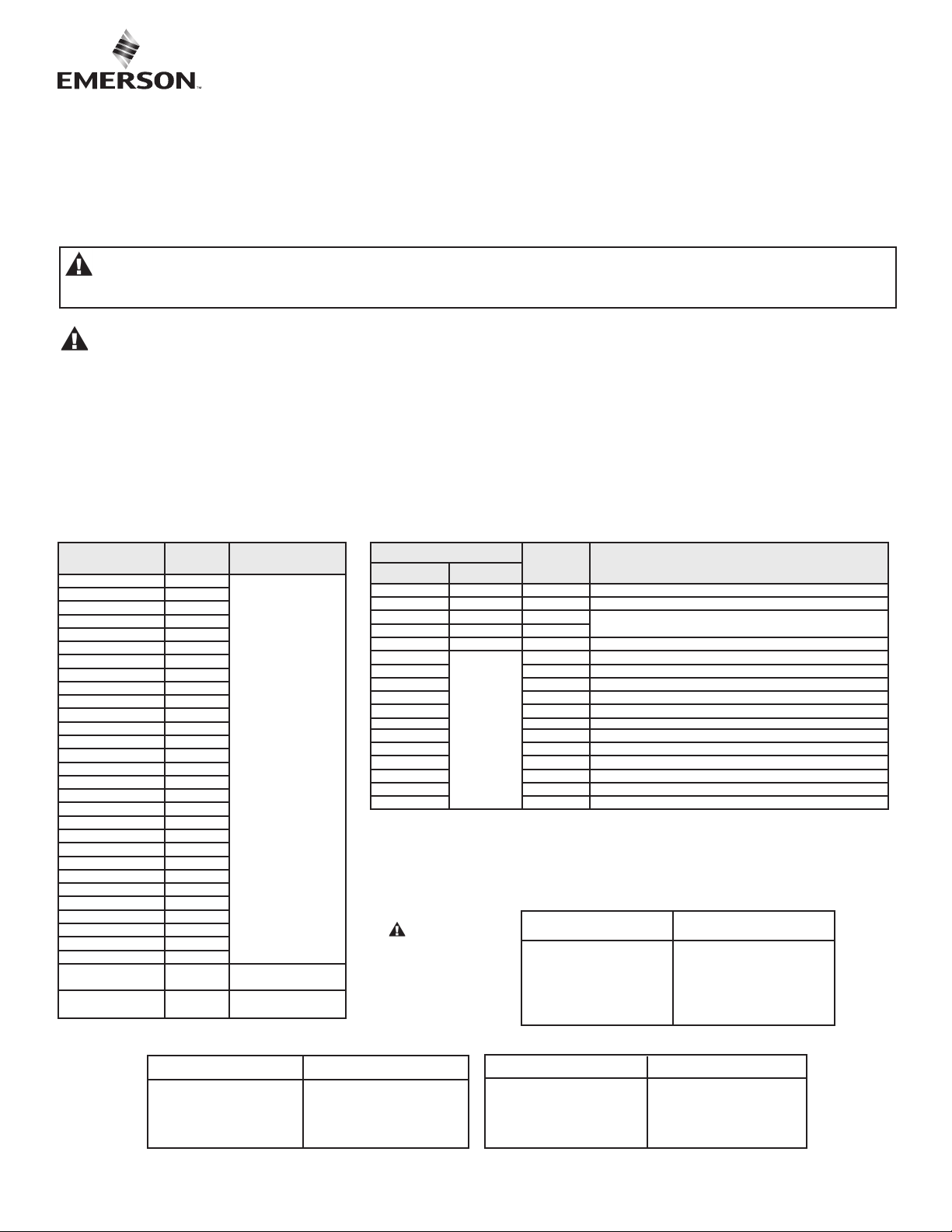
Appleton control assembly covers and devices are UL Listed for use with Appleton listed control assembly bodies, and are
UL Classied for use with UL Listed Crouse-Hinds bodies shown below.
ASSEMBLY: Check ground surfaces of all components for foreign material prior to assembly. Surfaces must be clean and
undamaged. Install the desired cover and device assembly on the body. Secure the cover assembly to the body by tightening the
screw provided with the cover.
The following cover with device and combination of cover and device are UL Listed control assemblies when assembled to Appleton
bodies and are UL Classied for use with the Crouse-Hinds bodies listed below. These combinations are suitable for use in Class I,
Group C and D; Class II, Group E, F, and G; and Class III hazardous locations.
COVER WITH
DEVICE*
EDKL-U3 YES
EDKL-J3 YES
EDKL-J1U2 YES
EDKL-J2U1 YES
EDK-DPB NO
EDKB-12 YES
EDKB-35 YES
EDKB-102 YES
EDKB-345 YES
EDKB-DU1 YES
EDKB-DU2 YES
EDKB-J1** YES
EDKB-J1DU1 YES
EDKB-J1U1 YES
EDKB-J1U2 YES
EDKB-J2 YES
EDKB-345-S636 YES
EDKB-U1
EDKB-U2
EDSK-B
EDKB-102-S634 YES
EDKB-102-S635 YES
EDKB-345-S634 YES
EDKB-345-S635 YES
EDKB-UM1
EDKB-DPB YES
EDKB-DPBM YES
EDKB-RU1 YES
EDKB-RU2 YES
EDKB-PC120 YES
EDKB-PC277
FACTORY
SEALED?
YES
YES
YES
YES
ELECTRICAL RATING
PUSHBUTTON
SWITCH
600 VAC MAX. HEAVY
PILOT DUTY
PILOT LIGHT 125 VAC
MAX. 60 Hz
1
25VAC-60HZ
1000VA LOAD
277VAC-60HZ
1000VA LOAD
COMBINATION OF
COVER* DEVICE
EDSK-MS EFS-2MS-Q NO 2P 30A-250VAC. 20A-600VAC, 2HP-230VAC. 3HP-575VAC
EDSK-MS EFS-3MS-Q NO 3P 30A-250VAC, 20A-600VAC, 3HP-125VAC, 15HP-600VAC
EDSK-RU1 EDS-RU1-Q NO
EDSK-RU2 EDS-MRU2-Q NO
EDS-F23W-Q YES 3W 20A-120VAC, 20A-277VAC, 1HP-120VAC, 2HP-240VAC
EDS-F24W-Q
EDS-F33W-Q YES 3W 30A-120VAC, 30A-277VAC, 2HP-120VAC, 2HP-240VAC
EDS-F21-Q YES 1P 20A-120VAC, 20A-277VAC, 1HP-120VAC, 2HP-240VAC
EDS-F22-Q YES 2P 20A-120VAC, 20A-277VAC , 1HP-120VAC, 2HP-240VAC
EDS-F31-Q YES 1P 30A-120VAC, 30A-277VAC, 2HP 120,VAC, 2HP-240VAC
EDS-F32-Q YES 2P 30A-120VAC, 30A-277VAC, 2HP-120VAC, 2HP-240VAC
EDSK-1MSAB YES 1P 1HP-115/230VAC
EDSK-1MSW*** YES 1P 1HP-115/230VAC, 1/4HP-32VDC, 1/4HP-250DC
EDSK-2MSAB*** YES 2P 1HP-115/230VAC, 3/4HP-32VDC, 3/4HP-250VDC
EDSK-2MSW*** YES 2P 1HP115/230VAC, 1/4HP-32VDC, 1HP-125VDC, 1/4HP-250VDC
EDSK-MC2*** YES 2P 30A-250VAC, 20A-600VAC, 2HP-230VAC, 3HP-575VAC
EDSK-MC3 YES 3P 30A-250VAC, 20A-600VAC, 3HP-125VAC, 15HP-600VAC
* With or without sufx -A
** With or without sufx -S801, -S802, -S803, -S804
*** Heater table supplied with these devices must be afxed in or near the enclosure for future reference
Blank cover for use singly with 2-gang body only
Device rating must match rating stamped on cover
With or without sufx -L
WARNING: To prevent
ignition of Group C and D
atmospheres, seals must be
installed within ve (5) feet on
each conduit opening.
COVER WITH
DEVICE
FACTORY
SEALED?
600 VAC MAX
HEAVY PILOT DUTY
YES 4W 20A-120VAC, 20A-277VAC, 1HP-120VAC, 2HP-240VAC
APPLETON APPLETON
2-GANG TANDEM THREE DEVICE
EDS177 EDSC177 EDS147 EDSC147
EDS277 EDSC277 EDS247 EDSC247
EDS377 EDSC377 EDS347 EDSC347
EDS177-SA EDSC177-SA EDS147-SA EDSC147-SA
EDS277-SA EDSC277-SA EDS247-SA EDSC247-SA
EDS377-SA EDSC377-SA EDS347-SA EDSC347-SA
ELECTRICAL RATING
APPLETON APPLETON
1-GANG BODY 2-GANG BODY
EDS171 EDSC171 EDS172 EDSC172
EDS271 EDSC271 EDS272 EDSC272
EDS371 EDSC371 EDS372 EDSC372
EDS171-SA EDSC171-SA EDS172-SA EDSC172-SA
EDS271-SA EDSC271-SA EDS272-SA EDSC272-SA
EDS371-SA EDSC371-SA EDS372-SA EDSC372-SA
CROUSE-HINDS CROUSE-HINDS
1-GANG BODY 2-GANG BODY
EDS171 EDSC171 EDS172 EDSC172
EDS271 EDSC271 EDS272 EDSC272
EDS371 EDSC371 EDS372 EDSC372
EDS171-SA EDSC171-SA EDS172-SA EDSC172-SA
EDS272-SA EDSC271-SA EDS272-SA EDSC272-SA
EDS371-SA EDSC371-SA EDS372-SA EDSC372-SA
501581-001 Rev. P 03/27/17 • Page 1 of 4
Page 2
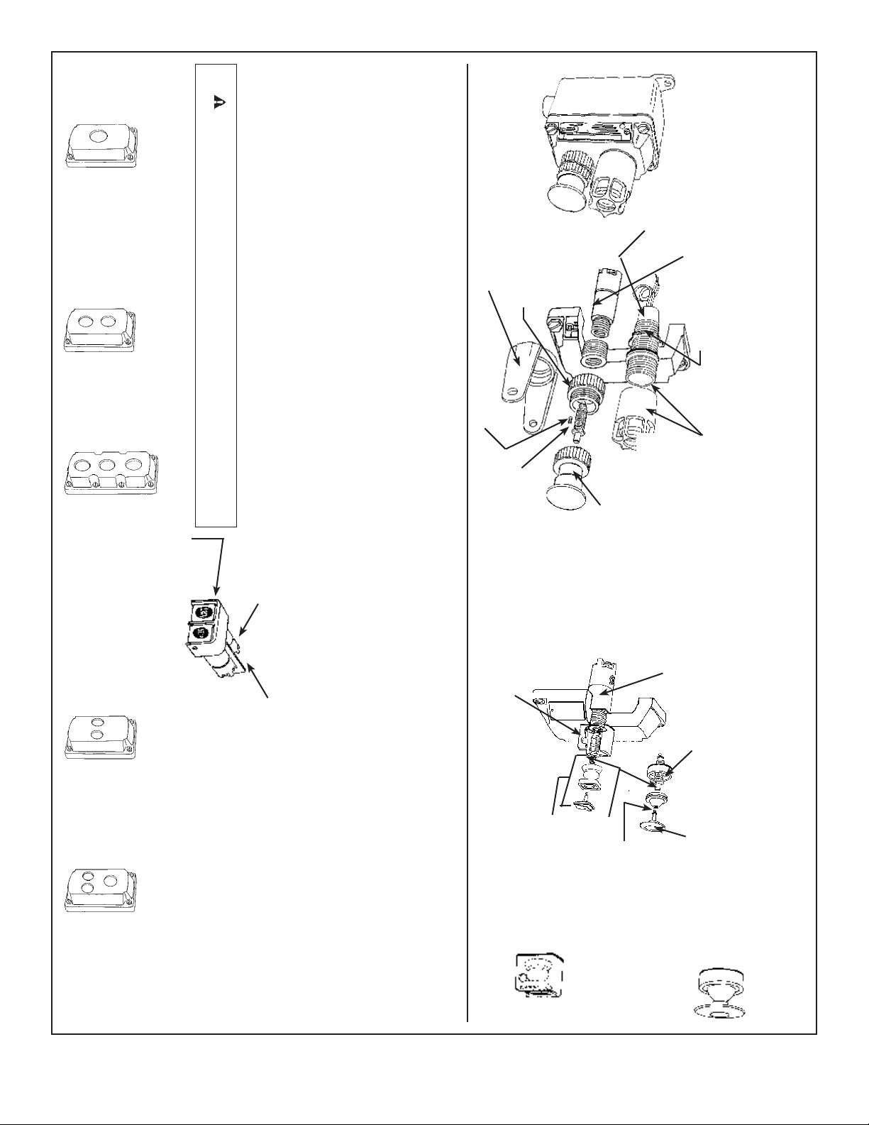
8. Check pushbutton switch and pilot light electrically and mechanically
for proper operation.
COLLAR MUST BE INSTALLED IN THE INTENDED MANNER AS SHOWN.
CAUTION: WHEN CHECKING PUSHBUTTON ELECTRICALLY GUARD OR
One Pushbutton
Switch Cover or one Pilot Light
EDSK-1 J
EDSK-1 J-A
6. Tighten shaft bushing with 1/2" nut driver to “lock” pushbutton in place, thread set
7. Thread Button and cover assembly onto collar until fully seated.
screw onto collar along side of hex at of shaft bushing.
5. Insert shaft into bushing. Put shaft bushing assembly thru hole in collar and thread
1/2" nut driver to remove shaft bushing and shaft from push assembly. (Set these parts
aside for later reassembly in step 5.)
face of cover.
bushing into pushbutton opening. Hold pushbutton from inside of cover to prevent it
from turning. If a Lockout Guard is used, put shaft bushing assembly thru collar
and lockout.
MAINTAINED CONTACT PUSHBUTTON SWITCH AND PILOT LIGHT
1. Pilot light must be installed in 3/4" 14 NPSM opening.
2. Pushbutton switch must be installed in 1/2" 14 NPSM opening.
3. Unscrew button and cover assembly from collar. Remove set screw from collar. Use a
4. Thread Push Button from inside of cover until front of pushbutton is ush with
Installation of Pushbutton Switch and Pilot Light in Contender® EDSK Series Covers
3/4" 14
NPSM
Tapped
Hole
EDSK-2J-A
3/4" 14
NPSM
Tapped
Holes
Three Pushbutton or
Three Pilot Lights or
Combination Pushbutton &
Pilot Light
EDSKL-3PB
EDSKL-3PBA
Two Pushbutton
Switch Cover or
Two Pilot Light Cover
EDSK-2J
GUARD & GASKET
TWO BUTTONS
DOUBLE PUSHBUTTON WITH TWO BUTTON GUARD
6. Press Weather Boot and Button assembly in shaft hole until fully seated.
SWITCH ASSEMBLY
7. Check pushbutton switch and pilot light electrically and mechanically for proper operation.
TWO PUSHBUTTON
OPTIONAL LOCK GUARD
COLLAR AND GASKET
ASSEMBLY
SET SCREW
SHAFT BUSHING
ASSEMBLY
ASSEMBLY
SINGLE PUSHBUTTON SWITCH WITH ONE BUTTON GUARD
2. Remove set screw from guard, use a 1/2" nut driver to remove shaft bushing and shaft from
3. Thread pushbutton from inside of cover until front of pushbutton is ush with face of cover
4. Insert shaft into bushing. Put shaft bushing assembly thru hole in guard and thread bushing
5. Tighten shaft bushing with a 1/2" nut driver to “lock” pushbutton switch in place. Thread set
into pushbutton opening. Hold pushputton from inside of cover to prevent it from turning.
screw onto collar along side of hex at on shaft bushing.
1. Single pushbutton with one button guard must be installed in 3/4" 14 NPSM opening.
pushbutton assembly (set a side for later assembly).
PUSHBUTTON
SET SCREW
SWITCH
SPLS-AM-B (AMBER)
SPLS-GR-B (GREEN)
SPLS-CL-B (CLEAR)
SPLS-OP-B (OPAL)
SPLS-BL-B (BLUE)
BUTTON AND COVER
PILOT LIGHT
LOCKNUT
PILOT LIGHT ASSEMBLY
SPLS-RE-B (RED)
Explosion-Proof and Dust-Ignition-Proof
1/2" 14 NPSM
Tapped Holes
EDS K-2SP-A
Tapped Hole
1/2" 14 NPSM
Tapped Holes
Two Pushbutton
Switch Cover
EDSK-2SP
Switch Cover or Pilot Light
& Two P. B. Switch Cover
EDSK-1JSS
EDSK-1JSS-A
3/4" 14 NPSM
two button guard must be installed into two
1/2" 14 NPSM openings (approximately
1-1/6" apart).
2. Proceed as in steps (2) through (6) above.
Be sure insulator is in place.
Three Pushbutton
INSULATOR
1. Double Pushbutton assembly, with
GUARD AND GASKET
ASSEMBLY NPB-LG1
BUTTON ASSEMBLY
NBN-WB
GUARD AND GASKET
ASSEMBLY NPB-LG1
WEATHER BOOT AND
SHAFT BUSHING
RUBBER BOOT
ASSEMBLY
PUSHBUTTON
SWITCH
COLLAR AND GASKET
ASSEMBLY
PUSHBUTTON
MUSHROOM
ASSEMBLY
BUTTON ASSEMBLY
NMRB-GR (GREEN)
NMRB-BL (BLACK)
NMRB-RE (RED)
MUSHROOM PUSH
501581-001 Rev. P 03/27/17 • Page 2 of 4
Page 3

7. Check Selector Switches electrically and mechanically for proper operation.
handle pointing to “OFF” marking on nameplate, press operator housing down rmly
on operator collar and fasten in place with four (4) housing screws.
assembly through collar into Selector Switch and tighten bushing securely.
the two 1/2" threaded holes in cover. Thread in Selector Switch from inside of cover.
(See Note)
3. Use 1/2" nut driver to remove shaft bushing.
4. Place operator collar and gasket assembly on face of cover and line up openings with
5. Insert shaft through shaft bushing. While holding Selector Switch, thread shaft/bushing
6. Insert operator handle and teon gasket in operator housing. With arrow in operator
SELECTOR SWITCH
1. Selector Switch must be installed in 1/2" 14 NPSM opening(s).
2. Remove four housing screws, operator housing and handle assembly.
SELECTOR
SWITCH
INSULATOR
GASKET ASSEMBLY
OPERATOR COLLAR AND
Installation of Selector Switch in Contender® EDSK Series Covers
SELECTOR SWITCH COVERS
EDSK-2SP
EDSK-2SP-A
Two 1/2" tapped holes
BLANK
HAND
BLANK
AUTO
FWD
REV
START - STOP
ON
UP
DOWN
OFF
START
RUN
STOP
JOG
BUSHING
HOUSING
SCREWS (4)
AUTO
AUTO
OFF
HAND
REM
OFF
SHAFT
SHAFT
TWO POSITION NAMEPLATE THREE POSITION NAMEPLATE
SHAFT BUSHING
OPERATOR HANDLE
ASSEMBLY
TEFLON GASKET
OPERATOR
HOUSING
NOTE: Threaded aluminum shell of Selector Switch Assembly MUST TOUCH the
under side of operator collar gasket for proper operation of mechanism.
CLAMPING
SCREW
ASSEMBLY
SWITCH
CLOSE-UP
B.
PLUG
If two Selector Switches are to be installed, make sure insulator is in place.
Explosion-Proof and Dust-Ignition-Proof
SELECTOR
A. If one Selector Switch is to be installed, close up remaining 1/2" opening from
inside of cover with close-up plug provided. Tighten securely with screwdriver.
Tighten clamping screw to insure water tightness.
SLNP-FR
SLNP-HA
SLNP-B
SELECTOR SWITCH COVERS
PILOT LIGHT AND
EDSK-1JSS
EDSK-1JSS-A
ESKB-3JPB
One 3/4" tapped hole on top
Two 1/2" tapped holes on bottom
HAND
FWD
RUN
1
OFF
OFF
OFF
OFF
AUTO
JOG
REV
2
SLNP102
SLNP-FOR
SLNP-HOA
SLNP-ROJ
SLNP-SS
SLNP-OO
SLNP-UD
HAND - OFF -AUTO
STOP
JOG
Ð
RUN
OFF
Ð
START
RUN
Ð
SLNP-JOR
SLNP-SRS
SLNP-B3
SLNP-AO
SLNP-AH
SLNP-OR
SLNP-RJ
LOCAL
HAND
AUTO
REV
OFF
OFF
OFF
OFF
HAND
FWD
REM
REM
SLNP-LOR
SLNP-HOR
SLNP-ROF
SLNP-AOH
5
SHAFT BUSHING
ASSEMBLY
6
HOUSING
SCREWS (4)
B
OPERATOR COLLAR AND GASKET
ASSEMBLY HOUSING
OPERATOR
HOUSING
501581-001 Rev. P 03/27/17 • Page 3 of 4
Page 4

PILOT LIGHTS
Nominal Volts
50/60 Hertz
Pilot Light Transformer
Source
Nominal 120V
Primary
Voltage
Source
Nominal 220, 440, 550V
SELECTOR SWITCHES
Left Center
Style Position Position Position
2 Position None
2 Circuit
2 Position None
4 Circuit
Voltages above 125 volts
Nominal Volts Primary
50/60 Hertz Voltage
Transformer Range
220-110 220-240
440-110 440-480
550-110 550-600
Right
PUSHBUTTON STATIONS
Momentary Maintained
1 Circuit 2 Cir
Universal Universal Universal
Always disconnect primary power source before
opening the enclosure for inspection or service.
cuit 1 Circuit
EDS snap switch (toggle)
sealing well with wiring
diagram.
Pilot lights and sealing wells
are furnished with pigtail
leads for eld connection by
use of wire nuts.
WARNING
3 Position
2 Circuit
3 Position
4 Circuit
Pushbutton Stations and Selector Switches Screw Terminals
NC= Normally Closed
NO
NC
NO= Normally Open
Factory Sealed Pushbutton
Switch is supplied with optional
NC
NO
Crimp-Type Terminal
Strip the insulation on each conductor wire back 3/8".
Use a slotted head screwdriver to loosen the eld wiring
terminal screws the required 3 or 4 turns.
Insert the bare wire conductor(s) on either side of the terminal
screw(s), under the terminal wire screw(s), and securely tighten
the screw(s). NOTE: Do Not exceed 15 in– lbs of torque.
C
D
B
Single Gang
3.72
5.88
1.31
5.31
.34 DIA.
2 Places
Two Gang
2.63
5.31
1. Frequent inspection should be made. A schedule
for maintenance checks should be detrmined by the
environment and frquency of use. It is recommended
that inspection should occur at least once a year.
2. Perform visual, electrical and mechanical checks on
all components on a regular base.
3. Visually check for undue heating evidenced by
discoloration of wires or other components, damaged
or worn parts or leakage evidenced by water or
corrosion in the interior.
4. Electrical check to make sure that all connections are
clean and tight, and that contacts in the components
make or break as required.
5. Mechanically check that all parts are properly
assembled, and that operating mechanisms
move freely.
5.88
Three Device
1.31
7.47
3.72
8.13
2-G Tandem
1.31
10.53
3.72
11.16
A
Hub Single Gang Two Gang Three Device 2-G Tandem
(in.) Dim. A Dim. B Dim. C Dim. D Dim. A Dim. B Dim. C Dim. D Dim. A Dim. B Dim. C Dim. D Dim. A Dim. B Dim. C Dim. D
1/2 .75 6.81 3.06 2.69 .88 6.81 3.06 2.69 1.00 9.19 3.06 2.69 .88 12.09 3.31 2.88
3/4 .88 6.81 3.06 2.69 .88 6.81 3.06 2.69 1.00 9.19 3.06 2.69 .88 12.09 3.31 2.88
1 1.00 7.03 3.06 2.69 1.00 7.03 3.06 2.69 1.00 9.19 3.06 2.69 1.00 12.31 3.31 2.88
Except as expressly provided by Appleton Grp, LLC (Appleton), Appleton products are intended for ultimate purchase by industrial users and for operation by persons trained and experienced in the use and maintenance of this equipment
and not for consumers or consumer use. Appleton warranties DO NOT extend to, and no reseller is authorized to extend Appleton’s warranties to any consumer.
While every precaution has been taken to ensure accuracy and completeness in this manual, Appleton Grp, LLC. assumes no responsibility, and disclaims all liability for damages resulting from use of this information or for any errors or
omissions. Specications are subject to change without notice. The Appleton and Emerson logos are registered in the U.S. Patent and Trademark Ofce. All other product or service names are the property of their registered owners.
©2017 Appleton Grp, LLC. All rights reserved.
1.31
7.41
1.31
1.31
 Loading...