

Page 1

INSTALLATION AND MAINTENANCE INSTRUCTIONS
CODE•MASTER 2™ PLT LUMINAIRE
Read carefully before attempting to install fi xture.
650438-000
INSTRUCTION SHEET
Class I, Div. 1 and 2, Groups C, D
Class II, Div. 1 & 2, Groups E,F,G
Class III
UL 1598A, 844
Suitable for Use in Wet Locations
Code•Master 2™ Factory Sealed Fixtures:
Explosion-Proof, Dust-Ignition-Proof;
52, 64 and 84 Watt PLT Compact Fluorescent.
Applications
• Ideal for use in chemical and petrochemical plants such as
manufacturers of plastics, paints and thinners in refi neries,
and in other process areas where ignitable vapors, dust,
moisture and corrosive elements may be present.
• Suitable for use in wet locations.
Features
• Fixtures operate safely in high ambient temperatures. For
example, in Class I areas the 84W PLT fi xture operates at a
maximum temperature of 85˚C in a 40˚C ambient. See chart
below for specifi c ratings.
• Arrangement of heat-producing components results in more
effi cient heat dissipation for cooler fi xture operations.
Classifi ed Area Suitability of Code•Master 2™ Series PLT Fixtures
(Suitability includes use of refl ector.)
Class I, Div. 1 & 2 with Globe or
UL/NEC Temp. Ident. No.
Lamp
Type
Lamp
Watts
Supply
Wire °C
Ambient
Temp °C
Nameplate
Marking
60 40 T6 (85 °C) C,D T4 (135 °C) E,F,G
PLT
(4-pin)
52
(2x 26)
75 55 T5 (100 °C) C,D — —
75 65 T5 (100 °C) C,D — —
60 40 T6 (85 °C) C,D T4 (135 °C) E,F,G
PLT
(4-pin)
64
(2x 32)
75 55 T5 (100 °C) C,D — —
75 65 T5 (100 °C) C,D — —
60 40 T6 (85 °C) C,D T4 (135 °C) E,F,G
PLT
(4-pin)
84
(2x 42)
75 55 T5 (100 °C) C,D — —
75 65 T5 (100 °C) C,D — —
• Patented “wireless” design. Threading of fi xture unit onto
mounting hood makes electrical connection. Only wiring
required is attaching two wires to connection block in mounting hood.
• Connection block is easily wired: (a) loosen two screws. (b)
make wire connections (c) re-position connection block.
• Safe, easy servicing without disconnecting any wiring.
“Wireless” fi xture unit easily threads off mounting hood for
convenient servicing or for immediate replacement with a
“stand-by” unit.
• Acme double lead threads speed installation and fi xture
removal from mounting hood-only half as many turns are
required as for single lead threads.
with Globe & Refl ector
Groups
Class II, Div. 1 & 2 with Globe or
with Globe & Refl ector
UL/NEC Temp. Ident. No.
Nameplate
Marking
Groups
“T” Numbers Represent the Maximum Surface Temperature for Class I, Div. 1 Locations and
Maximum Surface Temperature Under Dust Blanket for Class II, Div. 1 Locations.
“T”
Number
Temp.
Range
(˚C)
T1 350 325 T2 T2A T2B T2C T2D T3 T3A T3B T3C T4 T4A T5 T6
351-450 326-350 301-325 281-300 261-280 231-260 216-230 201-215 181-200 166-180 161-165 136-160 121-135 101-120 86-100 85
Rev. B 06/29/06 Page 1
Page 2
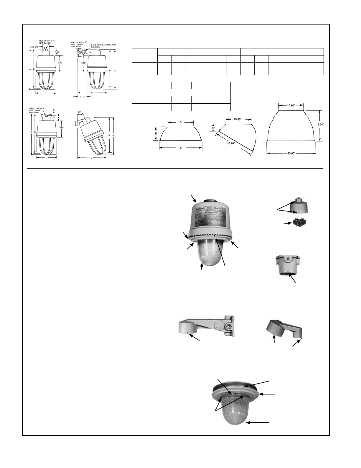
Dimensions
PENDANT
BRACKET
Dim. in
Inches
52, 64, 84
Watt
Type Refl ector A B C
Dimensions In Inches
CEILING
25° STANCHION
Standard Dome
Deep Dome
INSTALLATION AND MAINTENANCE INSTRUCTIONS CODE•MASTER 2™ PLT LUMINAIRE
Read carefully before attempting to install fi xture
VERIFY that the supply line voltage and fi xture nameplate volt-
age are compatible.
VERIFY that the fi xture operating temperature marked on nameplate
complies with temperature restrictions of hazardous area.
USE supply wire rated for ambient temperature to be encountered. See nameplate.
INSTALLATION OF MOUNTING ACCESSORIES:
PENDANT HOOD
Remove connection block from hood by loosening two mounting screws.
Thread hood onto conduit and tighten locking set screw. Connect the
ground wire to the green screw provided in hood. Connect supply wires
to connection block. Replace connection block into mounting hood and
tighten securely.
STANCHION ARM
Remove connection block. Thread stanchion onto conduit and
tighten locking set screw. Connect electrically as described under
pendant hood.
WALL BRACKET AND CEILING BOX
Install wall bracket or ceiling box on support surface with four bolts through
four external mounting holes. Remove connection block and connect
electrically as described under pendant hood.
INSTALLATION OF FIXTURE
Universal voltage (120-277V, 50-60Hz) fi xtures are completely
wired, needing no additional fi eld wiring.
REMOVING GLOBE-RING ASSEMBLY
Loosen round head locking screw in globe ring until screw clears
pry bars in ballast housing. Unthread globe-ring assembly (Do
not hold glass globe to unthread globe-ring assembly as this
might loosen globe locking ring. Should the globe locking ring be
accidentally loosened it must be retightened. Loosen set screw
in globe locking ring and tighten the locking ring, then retighten
the set screw.) A screwdriver inserted through slot in ring and
operated against pry bars in housing will assist in removing
globe-ring assembly.
WIRING UNIVERSAL VOLTAGE BALLAST (120-277V, 50-60Hz)
Loosen the two screws securing the socket support plate, remove
plate and set aside (enough slack in the wires is provided).
Locate fi xture lead marked “Line” and connect to ballast voltage
lead corresponding to supply voltage. Replace socket support
plate and tighten the two screws to secure into the fi xture.
Pendant Ceiling Bracket 25° Stanchion
ABCABCABCABC
24.5 23.5 12 24.36 23.36 12 24.61 23.61 17.5 22.2 21.2 17.5
11.2 5.9 18.7
10.56 7.0 20.3
PENDANT HOOD
LOCKING
SET SCREWS
CONNECTION
BLOCK
CEILING BOX
LOCKING
SET SCREWS
STANCHION
ARM
LOCKING
SET SCREWS
SET
SCREW
LOCKING
RING
GLOBE
GLOBE RING
SET SCREW
LOCKING RING
HOUSING
GLOBE
WALL BRACKET
LOCKING
SET SCREW
SCREWS FOR
REFLECTOR
AND GUARD
ROUND HEAD
SCREW
ROUND
HEAD
SCREW
SCREWS FOR
REFLECTOR
AND GUARD
P
age 2
650438-000 Rev. B 06/29/06
Page 3

INSTALLING LAMPS AND CLOSING FIXTURE
Check lamp type and wattage against fi xture nameplate,
then install lamps. Rethread globe-ring assembly into housing until hand tight and lock in place by driving locking screw
to engage pry bar.
GLOBE-RING ASSEMBLY TIGHTENING INSTRUCTIONS
The globe-ring assembly must be tightened to compress
gasket to insure watertightness. Thread globe-ring assembly
by hand until gasket makes contact with housing, then rotate
additionally past three notches or for 2 inches of travel. To
assist in rotating globe-ring assembly, use two screwdrivers
inserted through slots on opposite sides of ring and operated
against pry bars in housing.
INSTALLING FIXTURE ON MOUNTING ACCESSORY
Install assembled fi xture by threading into mounting acces-
sory, the electrical contacts will automatically engage. Insure
that fi xture is tightly threaded, then tighten locking set screw
in bottom of mounting accessory.
INSTALLATION OF REFLECTOR AND GUARD
Refl ectors and guards are provided with keyhole slots. To
install, loosen three screws in the globe ring and assemble
refl ectors or guards. Tighten the three screws. When an
angle refl ector is used, orient refl ector to direct the main light
beam near desired direction. Fine tune by rotating globe
ring assembly after loosening round head locking screw.
Retighten locking screw.
RELAMPING
CAUTION: DISCONNECT THE FIXTURE FROM SUPPLY CIRCUIT BEFORE OPENING TO SERVICE. KEEP
TIGHTLY CLOSED WHEN IN OPERATION.
To relamp, after disconnecting power, open fi xture as
described under “Removing globe-ring assembly.” Remove
old lamp and install new as described under “Installing lamp
and Closing Fixture.”
HOUSING
GASKET SILICONE
RUBBER
GLOBE RING
LOCKING RING
GLOBE
GLOBE-RING ASSEMBLY
Rotate additionally
past three notches
or for 2 inches of
travel
WIRING DIAGRAMS
650438-000 Rev. B 06/29/06 Page 3
Page 4

age 4
P
650438-000 Rev. B 06/29/06
 Loading...