

Appleton ATX™ SWD Series Isolator Switches, Circuit Breakers, “Break Glass” Call Points Catalog Page
Page 1
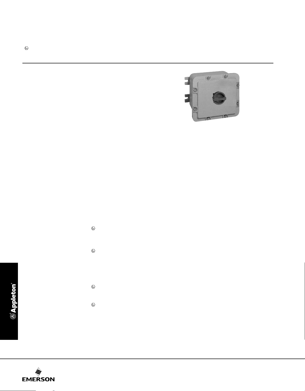
ATX™ SWD Series 20, 32, 63, 100, 125, 160 and 250 Amp Isolator Switches,
CONTROLS: ATEX/IECEx INCREASED SAFETY CALL POINTS STATIONS AND AUDIO SIGNALING DEVICES
© June 2017
Circuit Breakers and “Break Glass” Call Points
Flameproof
ATEX/IECEx:
Zone 1 and 2 - 21 and 22
II 2 GD
IP66 - IK10
Applications
• Designed to prevent operation in explosive atmospheres during
connect and disconnect operation of power loads.
• For use in hazardous areas where ignitable vapors, gases or
highly
combustible dusts are present.
• For installation in chemical and petrochemical plants, reneries
and other process industries.
Features
• Available up to 690 Volts, and up to 250 Amps.
• Padlockable handle in position “O”.
• 3 or 4-pole switch mechanism.
• ”NO-NC” early break auxiliary contact.
• Main contact termination: Up to 85 mm2 (0.2868 in2).
• Auxiliary contact termination: 2.5 mm
• Threaded cable entries:
two at bottom and one at top – M20 to M63
• Supplied with:
1 x M20 blanking plug
1 x M8 earth stud
2
(0.004 in2).
Standard Materials
• Box: marine grade aluminum alloy
• Captive screws: A2 stainless steel
Standard Finishes
• Box: gray paint
Options
• Visible break assembly including a window to view power
connection (only for 100 A to 160 A versions).
ATEX/IECEx Certifications and Compliances
• Certication Type: CF2D
— Gas: Zone 1 and 2
– Conforming to ATEX 94/9/CE: II 2 G
– Type of Protection: Ex d IIB
– Temperature Class: T6 for Ta ≤ +40 °C (+104 °F);
T5 for +40 °C (+104 °F) < Ta ≤+55 °C (+131 °F)
— Dust: Zone 21 and 22
– Conforming to ATEX 94/9/CE: II2 D
– Type of Protection: Ex tD A21
– Surface Temperature: T95 °C (T203 °F)
— Ambient Temperature: -40 °C to +55 °C (-40 °F to +131 °F)
— CE Declaration of Conformity: 50254
— ATEX Certicate: LCIE 02 ATEX 6061X
• Certication Type: CF
— Gas: Zone 1 and 2
– Conforming to ATEX 94/9/CE: II 2 G
– ATEX/IEC Protection: Ex d IIB
– Temperature Class: T6
— Dust: Zone 21 and 22
– Conforming to ATEX 94/9/CE: II2 D
– Type of Protection: Ex tD A21
– Surface Temperature: T80 °C (T176 °F)
— Ambient Temperature: -40 °C to +55 °C (-40 °F to +131 °F);
CF10B is -20 °C to +55 °C (-4 °F to +131 °F)
— CE Declaration of Conformity: 50229
— ATEX Certicate: LCIE 02 ATEX 6057X
— IECEx Certicate: LCI.08 0023X
• Index of Protection according EN/IEC 60529: IP66
• Impact Resistance (shock): IK10
• Internal Volume: >2 dm3 (122 in³) - 2 liters
EURASEC Certification
• Certication Type: CF2D
— EURASEC RU C-FR.ГБ05.B.00911
• Certication Type: CF
— EURASEC RU C-FR.ГБ05.B.00911
63 Amp Version
364
Page 2

ATX™ SWD Series 20, 32, 63, 100, 125, 160 and 250 Amp Isolator Switches,
CONTROLS: ATEX/IECEx INCREASED SAFETY CALL POINTS STATIONS AND AUDIO SIGNALING DEVICES
© June 2017
Circuit Breakers and “Break Glass” Call Points
Flameproof
ATEX/IECEx:
Zone 1 and 2 - 21 and 22
II 2 GD
IP66 - IK10
Catalog Numbering Guide
SWD 016 S 2 00 A V
Wiring Diagram No.
Series:
SWD - SWD Series
Zone 1, 2 – 21, 22
ATEX/IECEx Certified
Amperage: Cable Entry:
020 - 20 A
032 - 32 A
063 - 63 A
100 - 100 A
Switch Type Wiring Diagram No. Certified Type Weight kg (lb) Volume dm
20 A – 3 x M20 threaded entries (1 Top and 2 Bottom)
3-pole switch S300 CF2D 3.8 (0.15) 11 (671.3) SWD020S300B
4-pole switch S400 CF2D 3.8 (0.15) 11 (671.3) SWD020S400B
32 A – Bottom entries: 1 x M25 + 1 x M20 – Top entries: 1 x M25
3-pole switch S300 CF2D 3.8 (0.15) 11 (671.3) SWD032S300D
4-pole switch S400 CF10B 11 (0.43) 19.6 (1196.1) SWD032S400D
63 A – Bottom entries: 1 x M32 + 1 x M20 – Top entries: 1 x M32
3-pole switch S300 CF10B 11 (0.43) 19.6 (1196.1) SWD063S300E
4-pole switch S400 CF10B 11 (0.43) 19.6 (1196.1) SWD063S400E
100 A – Bottom entries: 1 x M40 + 1 x M20 – Top entries: 1 x M40
3-pole switch S300 CF20B 13 (0.51) 24.5 (1495.1) SWD100S300F
4-pole switch S400 CF20B 13 (0.51) 24.5 (1495.1) SWD100S400F
125 A – Bottom entries: 1 x M50 + 1 x M20 – Top entries: 1 x M50
3-pole switch S300 CF20B 13 (0.51) 24.5 (1495.1) SWD125S300G
4-pole switch S400 CF20B 13 (0.51) 24.5 (1495.1) SWD125S400G
160 A – Bottom entries: 1 x M50 + 1 x M20 – Top entries: 1 x M50
3-pole switch S300 CF40B 50.5 (1.99) 235.2 (14352.8) SWD160S300G
4-pole switch S400 CF40B 50.5 (1.99) 235.2 (14352.8) SWD160S400G
250 A – Bottom entries: 1 x M63 + 1 x M20 – Top entries: 1 x M63
3-pole switch S300 CF60B 112 (4.41) 646.6 (39458.0) SWD250S300H
4-pole switch S400 CF60B 112 (4.41) 646.6 (39458.0) SWD250S400H
Switch Type:
S - Switch
C - Changer or
Selector Switch
125 - 125 A
160 - 160 A
250 - 250 A
Number of Poles:
2 - 2-pole
3 - 3-pole
4 - 4-pole
Contact Configuration:
00
01
02
A - 2 x M20
B - 3 x M20
C - 2 x M25
D - 2 x M25 + 1 x M20
E - 2 x M32 + 1 x M20
Options:
V - Visible Break
F - 2 x M40 + 1 x M20
G - 2 x M50 + 1 x M20
H - 2 x M63 + 1 x M20
J - 2 x M63 + 1 x M25
3
(in3) Catalog Number
Switching Arrangement — X Denotes ”Closed Contact”
S300 S400
Contacts Contacts
Positions 1-2 3-4 5-6 Positions 1-2 3-4 5-6 7-8
0 0
1 X X X 1 X X X X
For 100, 125 and 160 Amp versions only.
365
Page 3

ATX™ SWD Series 20, 32, 63, 100, 125, 160 and 250 Amp Isolator Switches,
CONTROLS: ATEX/IECEx INCREASED SAFETY CALL POINTS STATIONS AND AUDIO SIGNALING DEVICES
© June 2017
Circuit Breakers and “Break Glass” Call Points
Flameproof
ATEX/IECEx:
Zone 1 and 2 - 21 and 22
II 2 GD
IP66 - IK10
Technical Data
Main Contacts 20 Amps 32 Amps 63 Amps 100 Amps 125 Amps 160 Amps 250 Amps
Rated Insulation Voltage (Ui) 800 V 800 V 800 V 800 V 800 V 800 V 800 V
Rated Operating Voltage (Ue)
Rated Operating Current (Ie) 25 A
Rated Surge Voltage (Uimp) 8 kV 8 kV 8 kV 8 kV 8 kV 8 kV 8 kV
Short Circuit Resistance
Switching Capacity
415 V 25 A 32 A 63 A 100 A 125 A 160 A 250 A
AC 21 A
AC 22 A
AC 23 A
AC 23 A
Motor Power
(kW)
DC 21
DC 22
DC 23
500 V 25 A 32 A 63 A 100 A 125 A 160 A 250 A
690 V 25 A 32 A 63 A 100 A 125 A 160 A 200 A
415 V 25 A 32 A 63 A 100 A 125 A 160 A 250 A
500 V 25 A 32 A 63 A 100 A 125 A 125 A 250 A
690 V 25 A 32 A 63 A 63 A 80 A 100 A 125 A
230 V 25 A – – – – – –
415 V 25 A 32 A 63 A 100 A 125 A 125 A 250 A
500 V 25 A 25 A 63 A 80 A 100 A 100 A 200 A
690 V 25 A 25 A 40 A 63 A 80 A 80 A 100 A
230 V – – – – – – –
415 V 11 kW 15 kW 30 kW 45 kW 55 kW 75 kW 132 kW
500 V 11 kW 15 kW 30 kW 45 kW 55 kW 75 kW 140 kW
690 V 15 kW 18.5 kW 30 kW 45 kW 75 kW 75 kW 90 kW
Flexible Termination
Solid Termination 10 mm
Auxiliary Contacts
Rated Operating Voltage (Ue) 230 V/400 V 250 V 250 V 250 V 250 V 250 V 230 V/400 V
Rated Operating Current (Ie) 6 A/4 A 5 A 5 A 5 A 5 A 5 A 4 A/3 A
Switching Capacity
AC 15 6 A/230 V 5 A/250 V 5 A/250 V 5 A/250 V 5 A/250 V 5 A/250 V
DC 14 – – – – – –
Flexible Termination 2.5 mm
Two contacts connected in series.
415 V/500 V/
690 V
50 kA
(with fuse)
24/48 V, 25 A
– – – –
– – – – – –
– – – – – –
– – – – – –
– – – – – –
– – – – – –
– – – – – –
– – – – – –
0.75 to 6 mm
(0.001 to 0.009 in2)
2
(0.016 in2) 16 mm2 (0.025 in2) 50 mm2 (0.076 in2) 70 mm2 (0.109 in2) 70 mm2 (0.109 in2) 70 mm2 (0.109 in2) 150 mm2 (0.233 in2)
2
(0.004 in2) 2.5 mm2 (0.004 in2) 2.5 mm2 (0.004 in2) 2.5 mm2 (0.004 in2) 2.5 mm2 (0.004 in2) 2.5 mm2 (0.004 in2) 2.5 mm2 (0.004 in2)
2
415 V/500 V/
690 V
32 A/32 A/
25 A
50 kA
(with fuse)
– – – – –
16 mm
(0.025 in2)
2
(0.006 to 0.054 in2)
415 V/500 V/
690 V
63 A/63 A/
40 A
50 kA
(with fuse)
4 to 35 mm
415 V/500 V/
(with fuse)
2
4 to 50 mm
(0.006 to 0.078 in2)
690 V
100 A 125 A
100 kA
415 V/500 V/
690 V
63 kA
(with fuse)
800 V, 125 A 800 V, 125 A 440 V, 200 A
2
4 to 50 mm
(0.006 to 0.078 in2)
2
415 V/500 V/
690 V
160 A/160 A/
125 A
80 kA
(with fuse)
4 to 50 mm
(0.006 to 0.078 in2)
2
415 V/500 V/
690 V
250 A/250 A/
200 A
50 kA
(with fuse)
220 V, 250 A
500 V, 200 A
220 V, 250 A
440 V, 200 A
500 V, 200 A
220 V, 250 A
440 V, 200 A
500 V, 200 A
2
95 mm
(0.147 in2)
4 A/230 V -
3 A/400 V
1 A/24 V -
0.2 A/48 V
366
Page 4

ATX™ SWD Series 20, 32, 63, 100, 125, 160 and 250 Amp Isolator Switches,
240 mm (9.45”)
4 Ø 9 mm (0.35”)
270 mm (10.63”)
270 mm (10.63”)
320 mm (12.60”)
411 mm (16.18”)
25 mm (0.98”)
74 mm
680 mm (26.77”)
CONTROLS: ATEX/IECEx INCREASED SAFETY CALL POINTS STATIONS AND AUDIO SIGNALING DEVICES
© June 2017
Circuit Breakers and “Break Glass” Call Points
Flameproof
Dimensions in Millimeters (Inches)
CF2D
Fix. 245 mm (9.65”)
Ø 11 mm (0.43”)
126 mm (4.96”)
196 mm (7.72”)
145 mm (5.71”) 14 mm (0.55”)
212 mm (8.35”)
CF10B CF20B
Fix. 245 mm (9.65”)
15 mm
(0.59”)
370 mm (14.57”)
260 mm (10.24”)
Fix. 140 mm (5.51”)
Fix. 208 mm (8.19”)
(1.91”)
48.5 mm
Ø 11 mm (0.43”)
Fix. 250 mm (9.84”)
15 (0.59”)
Fix. 208 mm (8.19”)
74 mm
(2.91”)
Fix. 245 mm (9.65”)
CF40B CF60B
440 mm (17.32”)
Fix. 376 mm (14.80”)
Ø 11 mm
(0.43”)
Fix. 391 mm (15.39”)
455 mm (17.91”)
347 mm (13.66”)
74 mm
(2.91”)
Ø 14 mm
(0.55”)
Fix. 616 mm (24.25”)
413 mm (16.26”)
(2.91”)
367
 Loading...