

Page 1

Zone 1 & 2 - 21 & 22 ATEX IECEx CE II2 GD
N U (
B
)
24
68
(
A
)
+–
01
• Luminaires (normal et de secours) - Type FLd
• Lighting (normal and emergency) - Type FLd
•Cветильники (постоянного и аварийного освещения) -Тип FLd
NT 250 0548/00
Milieu / Environment / Ambiente / Umgebung Gaz - Gas - Gas - Gas Poussières - Dust - Stäube - Polvos
Marquage / Marking / Marcado / Kennzeichnung
Symbole de protection CENELEC / CENELEC protection symbol
Symbole de protection CEI / IEC protection symbol
Ex d IIC Ex tD A21 T80°C
Classe de température / Temperature class T6 /
Attestation CE de type / EC certificate LCIE 97 ATEX 6012
Certificat IECEx / IECEx certificate IECEX LCI 04.0018
Température ambiante / Ambient temperature - 40°C à/to + 55°C
Indice de protection / Protection index IP66/68 (10m) - IK07
• la plage de température optimale pour la batterie est de - 5°C à + 30°C • Optimum operating temperature for battery is - 5°C to + 30°C
Batterie
Battery
батарея
Cotes d'encombrement et de fixation
•
Dimensions and fixing points
•
•Габаритные и крепежные размеры
DBAESLEDSLMA
F
FDBAESLEDSLMAW
FDBAESLEDSLNA
DBAESLEDSLNAW
F
+ 5°C --> + 25°C
• Utilisation • Non permanent adressable
• Use • Non-maintened addressable
Réf. / Ref.
FDBAESLEDSLMA
FDBAESLEDSLMAW
FDBAESLEDSLNA
FDBAESLEDSLNAW
Flux nominal 400 lm
LED
Nominal flux 400 lm
Номинальная светимость 400 лм
Puissance lampe / Lamp power
• Raccordement
• Wiring
•Соединения
• Marquage
• Marking
•Маркировка
• Interrupteur
Switch
•
•Рубильник
Autonomie 1 h
1 hr standby time
Автономная работа 1час3
Alimentation : 230V 50Hz
Alimentation : 230V 50Hz
Питани : 230В 50Гц
• Coté extraction platine
Plate withdrawal side
•
Вид со стороны
•
извлечения пластины
M20 ou/or 3/4 NPTM20 ou/or 3/4 NPT
Consommation : 1,1W
Consumption : 1,1W
Расход электроэнергии: 1,1Вт
• Ouverture
• Opening
•Открывание
• Dévisser le couvercle
• Unscrew the cover
•Отвинтить крышку
FDBAESLEDEMAW
FDBAESLEDENAW
• Raccordement télécommande
• Remote control wiring
•Подключение дистанционного управления
1/15
Page 2

• Fermeture
1/4
10
• Closing
Закрывание
•
• Maintenance
• Maintenance
•Обслуживание
1/4 de tour
1/4 turn
Couple de serrage préconisé au remontage : 32 N.m (±10%)
•
• When remounting, fasten fixing nuts to 32 N.m (±10%)
•Рекомендованный момент затяжки при повторном монтаже: 32 N.m (±10%)
Attention ! Avant d’ouvrir l’appareil mettre l'alimentation
•
(et la télécommande) hors tension.
Caution ! Before opening the unit switch off mains power
•
nd the remote control).
a
Внимание! Перед тем, как открывать прибор,
•
отключить напряжение (и дистанционное управление)
• Dévisser le couvercle
Unscrew the cover
•
•Отвинтить крышку
Graisser les filetages
•
Loctite GR135 ou Molydal M03
Grease the threads
•
octite GR135 or Molydal M03)
L
• Смазать резьбы
(Loctite GR135 или Molydal M03)
• Démontage de la platine
• Removing the geatray
• Демонтаж пластины
• Ouverture
• Opening
•Открывание
• Important ! Baisser le capot de sécurité.
• Important ! Lower the safety cover.
• Важно! Опустить защитный кожух.
• Remontage de la platine
• Reassembly of geartray
• Повторный монтаж пластины
• Débrocher le bornier
• Disconnecting the terminal block
• Отсоединить клеммную колодку
• Rebrocher le bornier. Fixer la terre
• Reconnecting the terminal block. Fit the ground
• Снова подсоединить клеммную колодку.
Подключить заземление
• Couple de serrage préconisé au remontage : 2,85 N.m (±15%)
• When remounting, fasten fixing nuts to 2,85 N.m (±15%)
•Рекомендованный момент затяжки при
повторном монтаже: 2,85 N.m (±15%)
2/15
Page 3

Cotes d'encombrement et de fixation
10
1/4
•
• Dimensions and fixing points
Габаритные и крепежные размеры
•
DBAESLEDEMA
F
DBAESLEDENA
F
Raccordement
•
Wiring
•
•Соединения
• Marquage
• Marking
Маркировка
•
• Ouverture
• Opening
•Открывание
• Débrocher le bornier
• Disconnecting the terminal block
•Отсоединить клеммную колодку
Raccorder au réseau
•
• Wire connexions
•Подключить к сети
• Rebrocher le bornier.
Reconnecting the terminal block.
•
•Снова подсоединить
леммную колодку.
к
2 entrées en passage taraudées (3/4” NPT - M20)
•
livré avec un bouchon obturateur (3/4” NPT - M20)
2 threaded entries (3/4” NPT - M20)
•
- supplied with one blanking plug (3/4” NPT)
•2 сквозных входных отверстия с
езьбой (3/4" NPT - M20)
р
Поставляется с заглушкой (3/4" NPT - M20)
-
Coté extraction platine
•
Plate withdrawal side
•
•Вид со стороны
извлечения пластины
Raccordement télécommande
•
• Remote control wiring
•Подключение
истанционного управления
д
• Fermeture
• Closing
•Закрывание
1/4 de tour
1/4 turn
• Maintenance
• Maintenance
•Обслуживание
• Démontage de la platine
• Removing the geatray
• Демонтаж пластины
• Couple de serrage préconisé au remontage : 32 N.m (±10%)
• When remounting, fasten fixing nuts to 32 N.m (±10%)
•Рекомендованный момент затяжки при повторном монтаже: 32 N.m (±10%)
• Attention ! Avant d’ouvrir l’appareil mettre l'alimentation
(et la télécommande) hors tension.
• Caution ! Before opening the unit switch off mains power
and the remote control).
• Dévisser le couvercle
• Unscrew the cover
•Отвинтить крышку
•Внимание! Перед тем, как открывать прибор,
отключить напряжение (и дистанционное управление)
• Graisser les filetages
Loctite GR135 ou Molydal M03
• Grease the threads
Loctite GR135 or Molydal M03)
• Смазать резьбы
(Loctite GR135 или Molydal M03)
• Ouverture
• Opening
• Открывание
• Important ! Baisser le capot de sécurité.
• Important ! Lower the safety cover.
• Важно! Опустить защитный кожух.
• Débrocher le bornier
• Disconnecting the terminal block
• Отсоединить клеммную колодку
3/15
Page 4

• Remontage de la platine
28
28
• Reassembly of geartray
Повторный монтаж пластины
•
• Couple de serrage préconisé au remontage : 2,85 N.m (±15%)
• When remounting, fasten fixing nuts to 2,85 N.m (±15%)
Рекомендованный момент затяжки при повторном монтаже: 2,85 N.m (±15%)
•
• Accessoires de fixation
• Attachment accessories
Крепежные аксессуары
•
Rebrocher le bornier. Fixer la terre
•
Reconnecting the terminal block. Fit the ground
•
Снова подсоединить клеммную колодку.
•
одключить заземление
П
Réflecteur extérieur : voir auprès du constructeur
•
• External reflector : s
•Внешний рефлектор: обратиться к изготовителю
ee with manufacturer
• Montage du réflecteur
• Fitting the reflector
• Монтаж рефлектора
• Pièces de maintenance : voir auprès du constructeur
• Maintenance parts : see with manufacturer
• Запчасти для техобслуживания: обратиться к изготовителю
Fixation sur tube 1" 1/4 Ø42, 2 x 1" 1/2 Ø49)
•
Attachment on tube 1" 1/4 Ø42, 2 x 1" 1/2 Ø49)
•
Крепеж на трубе 1" 1/4 Ø42, 2 x 1" 1/2 Ø49)
•
• 2 étriers FDHC49Z
• 2 stirrups FDHC49Z
•2 скобы FDHC49Z
• 4 vis auto-taraudeuses M5
• 4 self tapping screws (M5)
• 4 Саморезы (М5)
Fixation rapide
•
Fast fixing
•
Быстрый крепеж
•
DFBZ
F
- Platine équipée
- Tube scellé dans les embouts
- Batteries antidéflagrantes
- Fitted plate
- Tube sealed in ferrules
- Flameproof batteries
- Снаряженная пластина
- Лампа, герметически заделанная в наконечники
- Взрывобезопасные батареи
• Mise en service
• Putting into service
•Ввод в эксплуатацию
• Mettre sous tension. Le voyant SATI vert clignote durant 12h. 2 diodes allumées.
• Switch on, Green SATI indicator flashes during 12h. 2 LEDs ligh.
• Nota : dans le cas d’un stockage prolongé des blocs, le clignotement des leds dure jusqu’à ce que les accumulateurs aient retrouvé leur tension.
Ensuite la led verte clignote seule jusqu’à ce que les accumulateurs soient complètement chargés. Une fois chargés, la led verte s’allume en fixe.
• Note : if the units have been stored a long time, the LED flashing lasts until the batteries recover their voltage.
Then the green LED flashes alone until the batteries are fully charged. Once charged, the green LED switches to steady.
• Примечание: после длительного хранения блоков мигание индикаторов продолжается, пока аккумуляторы не наберут минимальный заряд.
Затем до полной зарядки аккумуляторов мигает только зеленый индикатор. После полной зарядки индикатор постоянно горит зеленым.
4/15
Page 5

• Principe de fonctionnement
• Operating principle
Принцип действия
•
Etat de veille (secteur présent, charge batterie, led
•
erte allumée + 2 leds allumées).
v
• Standby status (mains power present, battery charge, green
led switches + 2 LEDs ligh)
Le bloc peut être mis au repos ou rallumé par action sur les poussoirs ALLUMAGE et EXTINCTION du
•
coffret de télécommande 039 01.
Au retour du secteur le bloc se remet en veille après 30 secondes..
The unit can be set to rest or reset by using the ON and OFF pushbuttons of the remote control 039 01.
•
The self-contained emergency lighting luminaire will go back to the rest mode after 30 seconds.
• Contrôle général de l’installation
tout moment il est possible d’effectuer l’allumage de tous les blocs pour vérifier visuellement
A
leur bon fonctionnement sans interrompre l’activité de l’établissement (réception installation,
isite de contrôleur...).
v
- Appuyer une fois sur la touche ALLUMAGE du coffret de télécommande
039 01, la led s’allume pendant 6 secondes,
3 secondes après, le bloc passe en état de fonctionnement.
- Pour arrêter le contrôle, appuyer sur la touche EXTINCTION
du 039 01.
Nota : cette opération n’a aucune incidence sur la signalisation des leds
des blocs.
• General installation check
All the units can be switched on at any time to check correct operation visually without
interrupting the activity of the establishment (installation acceptance, inspectors visit, etc).
- Press the ON button on remote control 039 01, the LED switches on for 6 seconds, after 3
seconds, the unit switches to operating status.
- To stop the check, press the OFF button of 039 01.
Etat de fonctionnement (secteur absent, pas de
•
harge batterie, 6 leds forte puissance.
c
• Operating status (no mains power, no battery
charge, 6 leds high power).
•
В любой момент есть возможность включить все блоки для
визуальной проверки из работы, не нарушая деятельности
предприятия (приемка оборудования, визит проверяющего…).
- Нажать один раз на клавишу ВКЛЮЧЕНИЕ на
коробке дистанционного управления 039 01,
при этом на 6 секунд загорится индикатор, а 3
спустя 3 секунды блок перейдет в рабочий
режим.
- Для остановки контроля нажать на ОТКЛЮЧЕНИЕ коробки
039 01.
Примечание: эта операция никак не влияет на показания
индикаторов блоков.
Note : this operation has no effect on the LED signalling of the units.
Etat de repos (secteur absent, pas de charge batterie,
•
eds éteintes).
l
• Rest status (no mains power, no battery charge,
leds off).
Блок может быть отключен и включен нажатием на
•
кнопки ВКЛЮЧЕНИЕ и ВЫКЛЮЧЕНИЕ коробки
дистанционного управления 039 01.
При подключении к сети блок через 30 секунд переходит
в режим ожидания.
Общий контроль оборудования
• Principe de fonctionnement (suite)
• Operating principle (continued)
• Принцип действия
• Mise en repos par le coffret de télécommande
Secteur absent : une pression sur le poussoir EXTINCTION met le bloc au repos.
Une pression sur le poussoir ALLUMAGE remet le bloc en fonctionnement.
Retour du secteur : le bloc se remet en veille après 30 secondes.
• Setting to rest using remote control
With no mains power : pressing the OFF button once sets the unit to rest. Pressing the ON
button once resets the unit to operation.
Restoration of mains power: the unit switches to standby after 30 seconds.
Отключение при помощи коробки дистанционного
управления Сети нет: нажатие на кнопку ВЫКЛЮЧЕНИЕ
отключает блок.
Нажатие на кнопку ВКЛЮЧЕНИЕ переводит его в рабочий режим.
При включении сети: блок переходит в режим ожидания через
30 секунд.
5/15
Page 6

• Tests automatiques
Ce bloc possède un microprocesseur et une horloge interne qui lui permettent de
’auto-tester :
s
Tous les 7 jours : test des lampes pendant 6 secondes. Le bloc choisit un jour pour réaliser
-
e test des lampes. Toutes les semaines, le même jour à la même heure le test lampe sera
l
ffectué.
e
- Tous les 70 jours : test des lampes et des accumulateurs pendant 1 heure, un générateur
léatoire choisit le jour. L’heure de test sera l’heure de la première mise sous tension du bloc
a
les accumulateurs ayant une tension suffisante).
(
Le bloc choisit une semaine dans le trimestre pour réaliser un test d’autonomie en plus du
-
test lampe. Pendant les tests la led clignote en vert.
lle passera en vert fixe lorsque le test sera correct et le bloc à nouveau opérationnel (charge
E
e 12 heures après la fin d’un test autonomie).
d
- Aucune autre opération n’est à réaliser.
ota : si malgré la génération aléatoire du jour de test, 2 blocs voisins ont leurs tests réali-
N
és simultanément, signalé par le clignotement de leur led verte, il est nécessaire de décaler
s
l’un d’eux (voir paragraphe “choix de l’heure du test, choix de l’heure par bloc”).
• Automatic tests
he unit has a microprocessor and internal clock for automatic testing :
T
Every 7 days : 6 second lamp test. The unit selects a day to perform lamp tests. Every
-
week on the same day at the same time the lamp test will be performed.
Every 70 days : 1 hour test of lamps and batteries, a random number generator selects the
-
ay. The test time will be the time of first supplying power to the unit
d
batteries having enough voltage).
(
- The unit selects one week in the quarter to perform an autonomy test in addition to the
lamp test. During the tests the LED flashes green. It switches to steady green when the test
s correct and the unit is again operational (12 hour charge after the end of the autonomy test).
i
• Exploitation particulière
• Special usage
• Особые режимы эксплуатации
No other operation has to be performed.
-
ote : if despite the random generation of the test day, 2 neighbouring units have their tests
N
erformed simultaneously, signalled by their green LED flashing, it is necessary to offset one
p
rom the other (see paragraph "choice of test time, choice of time by unit")
f
• Автоматическое тестирование
анный блок имеет микропроцессор и внутренние часы, которые ему
Д
озволяют производить авто-тест.
п
Каждую неделю: тест ламп в течение 6 секунд. Блок определяет день
для теста ламп. Тест ламп будет выполняться каждую неделю в один
ень и час.
д
Каждые 70 дней: тест ламп и аккумуляторов в течение 1 часа; день
определяется генератором случайных чисел. Временем теста будет
время первой подачи напряжения на блок (подача достаточного
апряжения на аккумуляторы).
н
Блок выбирает неделю в квартале, чтобы провести тест на
автономность, а также тест ламп. Во время тестов индикатор
мигает зеленым.
осле удачного теста индикатор загорится постоянным зеленым, а блок
П
новь перейдет в рабочее состояние (12-часовя зарядка после теста на
в
автономность).
Никаких других операций не требуется.
римечание: если несмотря на случайную генерацию дня теста 2
П
соседних блока начали выполнять тесты одновременно, о чем будут
сигнализировать их мигающие зеленые индикаторы,
необходимо перенести время теста для одного из них (см.
араграф “ выбор времени теста, выбор времени для блока” ).
п
• Choix de l’heure des tests
Dans certains cas, pour des raisons d’exploitation, il est nécessaire d’imposer une heure de test. Avant toute opération, s’assurer que tous les blocs ont leur led verte allumée en fixe ou
clignotant. Si après 24 heures de charge, les leds de l’un des blocs clignotent toujours alternativement vert/orange, remplacer ses accumulateurs.
• Choice of test times
In some cases, because of use, it is necessary to set a test time. Before any operation, make sure that all the units have their green LED switched on either steady or flashing. If after 24
hours charge, the LEDs of one of the units still flashes alternately green/orange, replace the batteries.
• Выбор времени выполнения тестов
В некоторых случаях, по эксплуатационным причинам необходимо задать время проведения теста. Перед любой операцией нужно убедиться, что
зеленый индикатор горит постоянно или мигает на всех блоках. Если после 24 часов зарядки индикаторы одного из блоков постоянно мигают то
зеленым, то оранжевым, поменять аккумуляторы.
• 1) Choix global pour toute l’installation
Tous les blocs sont testés à la même heure. Cette programmation n’est possible que sur
une installation équipée de la télécommande par coffret réf. 039 01. (voir catalogue
LEGRAND). Le choix se fait secteur présent sur les blocs.
Note : if the installation is mixed, having some units not tested automatically, wait 3
seconds then end by pressing OFF.
All units are on standby. The units to be tested automatically will
be tested at the chosen time (the day will be different according to
the units).
Nota : la télécommande réf.039 01 doit être placée hors zone à risque
d’explosion.
- A l’heure choisie pour le test, appuyer sur la touche ALLUMAGE
du coffret de télécommande 039 01, la led verte s’allume 6
secondes et s’éteint.
- Avant 3 secondes, appuyer une seconde fois sur la touche
ALLUMAGE du 039 01, la led verte s’allume 6 secondes et
s’éteint.
- 3 secondes après, les leds des blocs clignotent alternativement vert/orange pendant 5
secondes, puis la led verte est fixe ou clignotante suivant l’état précédent. Les résultats des
tests précédents sont effacés.
Nota : dans le cas d’une installation panachée ayant certains blocs non testables
automatiquement, attendre 3 secondes puis terminer par une
impulsion sur EXTINCTION.
Tous les blocs sont en veille. Les blocs à test automatique seront
testés à l’heure choisie (le jour sera différent suivant les blocs).
• 1) Overall choice for whole installation
All units are tested at the same time. This programming is only possible with an installation
fitted with remote control unit Cat No. 039 01. Choice is made with mains power present to
all units.
Note : the remote control, Cat No. 039 01, must be placed outside the explosion hazard
zone.
- At the time chosen for the test, press the ON button
of the remote control 039 01, the green LED switches on for 6
seconds and switches off.
- Before 3 seconds, press the ON button of 039 01 a second
time, the green LED switches on for 6 seconds and switches off.
- 3 seconds after, the LEDs on the units flash alternately
green/orange for 5 seconds, then the green LED is on steady or flashing according to its
previous state. Previous test results are deleted.
• 1) Общий выбор для всего прибора
Все блоки тестируются в одно время. Такое программирование
возможно только на приборе, оборудованном дистанционным управлением посредством коробки код 039 01 (см. каталог LEGRAND).Выбор
делается при блоках, включенных в сеть.
Примечание: дистанционное управление код 039 01 должно быть
установлено вне взрывоопасной зоны.
- В выбранное для теста время нажать на
клавишу ВКЛЮЧЕНИЕ коробки дистанционного
управления 039 01, при этом зеленый индикатор
загорится на 6 секунд и погаснет.
- За 3 секунды до этого нажать во второй раз на
ВКЛЮЧЕНИЕ коробки 039 01, при этом зеленый индикатор загорится на 6
секунд и погаснет.
- 3 секунды спустя индикаторы блоков поочередно будут мигать зеленым
и оранжевым в течение 5 секунд, затем остается гореть или мигать
зеленый индикатор, в зависимости от предыдущего состояния.
Результаты предыдущего теста будут стерты.
Примечание: в случае со смешанными приборами, имеющим некоторые
блоки, которые не тестируются автоматически,
подождать 3 секунды, затем закончить нажатием на
ВЫКЛЮЧЕНИЕ.
Все блоки будут в режиме ожидания. Блоки,
тестируемые автоматически, будут тестироваться в
установленное время (в день, в зависимости от блоков).
6/15
Page 7

• Exploitation particulière
• Special usage
• Особые режимы эксплуатации
he previous test results will be deleted. The unit will be tested at the chosen time (the day
• 2) Choix de l’heure bloc par bloc
Tous les blocs doivent être programmés unitairement par action sur chaque appareil. A
l’heure choisie :
) Couper l’alimentation secteur de l’appareil (ou de la ligne d’appareil).
a
) Agir sur l’interrupteur batterie en ouvrant et fermant le couvercle.
b
c) Remettre l’appareil sous tension.
Après 5 secondes, la led orange s’éteint, la led verte est fixe ou clignotante suivant l’état
récédent.
p
es résultats des tests précédents sont effacés. Le bloc sera testé à l’heure choisie (le jour
L
era différent selon les blocs).
s
ota : ce choix est possible même si l’installation a déja été programmée comme en 1.
N
• 2) Choice of time unit by unit
ll units must be programmed singly by operating on each device. At the time chosen :
A
) Cut the mains power supply to the device (or the device line).
a
b) Reach the battery switch by opening and closing the cover.
) Return power supply to the device ;
c
fter 5 seconds, the orange LED switches off, the green LED is on steady or flashing
A
ccording to the previous state.
a
T
will be different according to the units).
ote : this choice is possible even if the installation has already been programmed as in 1.
N
• 2) Выбор времени для каждого блока
Необходимо программировать все блоки вместе, работая с каждым
ппаратом. В выбранное время:
а
) Отключите питание аппарата от сети (или всей линии аппаратов).
a
b) Используйте выключатель батареи, закрыв и открыв крышку.
c) Снова включите аппарат в сеть.
ерез 5 секунд оранжевый светодиод погаснет, а зеленый будет гореть
Ч
остоянно или мигать, в зависимости от предыдущего состояния.
п
Результаты предыдущих тестов стерты. Блок будет
протестирован в выбранное время (день будет различаться для каждого
лока).
б
Примечание: выбор возможен, даже если инсталляция уже была
апрограммирована, как в п.1.
з
• Mémorisation des résultats
Les résultats des tests sont mémorisés jusqu’à la réalisation d’un test identique bon, et jusqu’à remplacement de l’organe défectueux et la validation du dépannage.
• Results storage
est results are stored until the performance of an identical correct test, and until replacement of the faulty item and validation of the repair.
T
• Запоминание результатов
езультаты тестов запоминаются до выполнения удачного теста и до замены поврежденного узла и подтверждения устранения поломки.
Р
MAINTENANCE
La signification des deux diodes électroluminescentes est la suivante :
- Vert allumé = bloc en état de fonctionnement normal.
- Vert clignotant : test en cours ou battterie en reprise de charge après une
autonomie ou un test.
- Vert/jaune clignotant = en mode “classique”, acquittement durant 1 heure de la réception
d’une télécommande d’extinction en présence secteur.
- Jaune allume fixe = défaut du tube de secours*
- Jaune clignotant lent = défaut batterie**
- Jaune clignotant rapide = défaut de l’électronique***
* Changer les lampes défectueuses .
**Changer la batterie du bloc, refaire les opérations comme lors de la première
mise en service
*** Envoyer le bloc en réparation.
• En mode "adressable" tous les défauts sont reportés sur le PC de supervision (voir la noti-
ce du logiciel pour plus de détails).
Tout appareil reconnu défectueux doit être réparé le plus rapidement possible. Remplacer
la batterie tous les 4 ans ou dès que l'autonomie nominale n'est plus respectée.
Nota 1 : à chaque mise sous tension ou chaque fin de test correct, le bon
fonctionnement des leds est vérifiable grâce à une période de clignotement
vert/orange de 30 secondes.
Nota 2 : le défaut de veilleuse ne peut être vu que hors de la période de prise
de charge des accumulateurs.
MAINTENANCE
The signification of the two electroluminescent diodes is the following:
- Green LED lit on permanently : the self-contained luminaire is operating
normally and the battery charging correctly
- Green LED flashing : test under progress or battery recharging after a
duration test or a power failure.
- Green/yellow LED flashing alternatively : for standard self-contained
emergency lighting luminaires, these flashing LEDs indicate that the luminaire has received the information from the remote control for a time period of one hour while mains
power.
- Yellow LED on = emergency tube fault *
- Yellow LED flashing slowly = battery fault**
- Yellow LED flashing quickly = electronic change-over fault***
* Change the defective lamps.
**Change the battery pack; redo the procedure as for the first putting in service.
*** Send the battery pack for repair.
Any appliance found to be defective should be repaired as quickly as possible. Replace
the battery every 4 years or when the nominal autonomy is no longer respected.
whenever the unit is powered up or at the end of each correct test, correct operation
Note 1 :
of the LEDs can be checked by a 30 second period of flashing
green/orange.
Note 2 : the standby lamp fault can only be seen outside the period for charging the batteries.
ОБСЛУЖИВАНИЕ
Два светодиода имеют следующее значения :
- Горит зеленый: блок в нормальном рабочем состоянии.
- Зеленый мигает: выполняется тест, либо батарея заряжается после теста
на автономность или простого теста.
- Мигает зеленый и желтый: в « классическом» режиме означает
подтверждение в течение 1 часа с момента получения дистанционной
команды на выключение при наличии сети/в адресном режиме работы
указывает на отсутствие подключения к коробке интерфейса.
- Горит желтый = неисправность лампы аварийного освещения*
- Редко мигает желтый = неисправность батареи**
- Часто мигает желтый = неисправность электроники***
* Замените неисправные лампы.
**Замените батарею блока, снова проделайте операции, как при первом
вводе в эксплуатацию
*** Отправите блок на ремонт.
• В « адресном» режиме обо всех неисправностях сообщается на
контролирующий ПК (см. инструкцию программного обеспечения).
Любой аппарат, признанный неисправным, должен быть отремонтирован
как можно скорее. Меняйте батарею каждые 4 года, либо при сокращении
номинального времени автономной работы.
Примечание 1: при каждом подключении к сети или при каждом
окончании удачного теста правильная работа индикаторов может быть
проверена благодаря 30-секундному периоду мигания зеленым и
оранжевым.
Примечание 2: неисправность лампы режима ожидания можно увидеть
только после того, как зарядятся аккумуляторы.
7/15
Page 8

• Exploitation particulière
• Special usage
• Особые режимы эксплуатации
• Report momentané d’un test
Dans le cas où pour une utilisation inhabituelle des locaux, l’heure du test est gênante pour l’activité, il est possible de reporter de 24 heures tous les tests pouvant avoir lieu le jour en
question.
- Appuyer sur la touche ALLUMAGE du coffret 039 01, la led s’allume 6 secondes puis s’éteint.
Avant 3 secondes, appuyer une seconde fois sur la touche ALLUMAGE, la led s’allume 6 secondes et s’éteint.
-
- Avant 3 secondes, appuyer une troisième fois sur la touche ALLUMAGE, la led s’allume 6 secondes et s’éteint.
Nota : dans le cas d’une installation ayant certains blocs non testables automatiquement, terminer par une impulsion sur EXTINCTION du 039 01.
Tous les blocs qui devraient s’allumer dans les 24 heures ont leur test repoussé d’une journée. Ensuite le programme reprend son cours normal.
Temporary test delay
•
If the test time is inconvenient for an unaccustomed use of the premises, it is possible to delay by 24 hours all the tests liable to take place on the relevant day.
- Press the ON button on the remote unit 039 01, the LED switches on for 6 seconds then switches off.
Before 3 seconds, press the ON button a second time, the LED switches on for 6 seconds and switches off.
Before 3 seconds, press the ON button a third time, the LED switches on for 6 seconds and switches off.
-
ote : if the installation has some units not tested automatically, end by pressing OFF on the 039 01.
N
All the units that should switch on in the 24 hours have their test delayed one day. Afterwards the programme returns to its normal sequence.
• Временный перенос теста
случае нестандартного использования помещений, или когда время теста препятствует деятельности, можно перенести на 24 часа все тесты,
В
которые могли быть запланированы на этот день.
- Нажмите на клавишу ВКЛЮЧЕНИЕ коробки 039 01. Светодиод загорится на 6 секунд и погаснет.
- За 3 секунды до этого нажмите во второй раз клавишу ВКЛЮЧЕНИЕ; светодиод загорится на 6 секунд и погаснет.
За 3 секунды до этого нажмите в третий раз клавишу ВКЛЮЧЕНИЕ; светодиод загорится на 6 секунд и погаснет.
-
Примечание: если в инсталляции имеются блоки, не тестируемые автоматически, закончить операцию нажатием на ВЫКЛЮЧЕНИЕ коробки 039 01.
Все блоки, которые должны были включиться в течение 24 часов, перенесли тестирование на день. После это программа возвращается к своему
ормальному исполнению.
н
• Mise hors tension longue durée : (Exemple : établissement saisonnier) Après une longue période hors tension, il est possible que les accus aient perdu toute tension et que la
programmation soit perdue. Lors de la remise sous tension, les blocs signaleront le défaut par un clignotement vert/orange de leurs leds. Il sera nécessaire de reprogrammer.
• Leaving without power for long periods : (
lost. When restoring mains power supply, the units will indicate the fault with their LEDs flashing green/orange. It will be necessary to reprogram them.
• Длительное отключение от сети: (например: сезонное учреждение) После длительного периода отключения от сети, может случиться, что
аккумуляторы полностью разрядятся, и программа сбросится. При включении в сеть блоки будут сигнализировать об этом зеленым/оранжевым
миганием светодиодов. Понадобиться повторное программирование.
Eg. seasonal establishment) After a long period without power, it is possible that the batteries loose their voltage and the programme is
• Décalage définitif des tests : reprendre la même procédure que pour le choix de l'heure du test
• Permanent retiming of tests : repeat the same procedure as for the choice of test time.
• Окончательный перенос времени тестов: выполнить те же действия, что при выборе времени проведения теста.
• Arrêt d’un test en cours : dans le cas ou un test autonomie en cours gène l’exploitation, il est possible de l’arrêter immédiatement. Appuyer sur la touche
EXTINCTION du coffret de télécommande 039 01. Le test est stoppé et sera refait le lendemain.
• Stopping test under way : when use of premises is inconvenienced by an autonomy test under way, it is possible to stop it immediately. Press the OFF button on the remote control
unit 039 01. The test stops and will be performed the next day.
• Прерывание выполняемого теста: если начавшийся тест автономной работы препятствует эксплуатации, возможно его немедленное
прекращение. Нажмите на клавишу ВЫКЛЮЧЕНИЕ на коробке дистанционного управления 039 01. Тест будет прерван и выполнен снова на
следующий день.
• Cas particuliers : lorsqu’une mise hors tension est supérieure à 3 jours, les tests ne sont plus effectués. Le cycle de test reprendra après la remise sous tension et la recharge des
blocs, les tests prévus le jour de la remise sous tension sont automatiquement repoussés de 24 heures.
• Special cases : when mains power is off for longer than 3 days, tests are no longer performed. The test cycle will be restarted after mains power returns and the units are recharged ;
the tests planned for the day of the return of mains power are automatically delayed 24 hours.
• Особые случаи: если время отключения от сети превышает 3 дня, тесты больше не выполняются. Цикл тестов восстановится после включение
сети и зарядки блоков; тесты, запланированные на день отключения, автоматически переносятся на 24 часа.
8/15
Page 9

ONCEPTION DU BLOC
C
• Les blocs autonomes adressables effectuent automatiquement le contrôle réglementaire de
assage à l'état de fonctionnement toutes les semaines et de l'autonomie de la batterie toutes
p
es 13 semaines. La double signalisation lumineuse réalisée par diodes électroluminescentes
l
ermet de connaître en permanence l'état du bloc. Ils possèdent deux modes de fonctionne-
p
ment, "classique" ou "adressable", sélectionnables par les micro-interrupteurs situés sur le
circuit imprimé.
En mode "classique" (tous les micro-interrupteurs sur la position 1). Dans cette configura-
•
ion, il est possible d'avoir des blocs de différentes générations raccordés sur la même ligne
t
e télécommande.
d
• En mode "adressable" (les micro-interrupteurs sont positionnés en fonction de l'adresse
ffectée au bloc), le bloc utilise une ligne de télécommande spéciale fonctionnant en tant que
a
US informatique. Un boîtier d'interface spécifique, faisant également office de boîtier de
B
élécommande, relie la ligne de télécommande BUS à un PC qui assure la fonction de
t
supervision de l'installation.
MPORTANT : dans cette configuration tous les blocs doivent être de la série URAVISION et
I
onctionner en mode "adressable" (adresse valide). Conforme aux normes NFC 71-800,
f
FC 71-801 de 2000 et NFC 71-820, il est fabriqué sous la Marque de qualité NF AEAS.
N
Performance SATI ".
RINCIPE DE FONCTIONNEMENT
P
Commutation :
- Après une coupure lorsque le secteur revient, le bloc reste allumé pendant 30 secondes pour
permettre le rallumage des luminaires de l'éclairage normal
Après une décharge complète, une sécurité interdit le passage en secours tant que la
-
batterie n'a pas été légèrement rechargée
Test permanent en présence du secteur :
Test de la lampe témoin de charge
-
- Test des deux lampes de secours (incandescente) ou du tube (fluorescent)
- Test du chargeur
- Test de la tension batterie
Test hebdomadaire :
- Ce test vérifie le passage en secours en cas de coupure secteur et l'allumage de la ou des
deux lampes de secours. Ce test dure 15 secondes. Durant le test, la charge de la batterie est
interrompue et la lampe témoin de charge s'éteint.
Ce test ne peut s'effectuer que si le secteur est présent et si la batterie est en partie chargée
-
(3 heures de présence secteur après une décharge complète). Dans le cas contraire, le test est
différé jusqu'au retour secteur et la recharge suffisante de la batterie.
Un test complémentaire peut être lancé manuellement en appuyant un court instant sur le
-
bouton-poussoir du boîtier de commande de test en mode classique (voir p. 3). Durant ce test,
a charge batterie n'est pas interrompue et la lampe témoin de charge reste allumée pour
l
visualiser son bon fonctionnement en plus de la ou des lampes de secours.
Test trimestriel :
- Ce test vérifie l'autonomie d'une heure de fonctionnement sur la ou les deux lampes de
secours. Durant le test, la charge de la batterie est interrompue et la lampe témoin de charge
s'éteint.
- Ce test ne peut s'effectuer que si le secteur est présent et si la batterie est, presque
totalement chargée (22 heures de présence secteur après une décharge complète). Dans le cas
contraire, le test est différé jusqu'au retour secteur et la recharge suffisante de la batterie.
- Si le test est interrompu par une télécommande d'extinction, il se fera automatiquement après
un délai de 24 heures.
- Un test trimestriel complémentaire peut être lancé manuellement en appuyant durant plus de
5 secondes sur le bouton-poussoir du boîtier de commande de test en mode classique.
i le test ne peut pas être effectué immédiatement du fait d'une insuffisance de charge de la
S
batterie, la demande de test est mémorisée et le test se fera après la recharge de la batterie. La
émorisation est visualisée par le clignotement alterné des LEDS verte et jaune durant
m
secondes. Si un report de test est en cours il est annulé.
5
En mode "classique", le lancement de ce test, provoque également la programmation du
moment des tests, comme, décrit ci-dessous.
rogrammation selon trois possibilités :
P
) Sans programmation :
1
Sans programmation, les blocs feront leurs tests à l'heure de leur première mise sous
tension. Le jour des tests est réparti sur une période de 64 jours (le premier mois étant exclu)
e façon que deux blocs voisins ne fassent pas leurs tests dans la même journée. Les tests
d
ebdomadaires se font le même jour de la semaine et à la même heure que le test trimestriel.
h
2) Programmation individuelle (mode "classique" uniquement) :
En mode "classique", tous les blocs doivent être programmés unitairement par action sur
-
haque appareil à l'heure choisie pour la réalisation des tests, le jour des tests restant
c
léatoire.
a
- Couper l'alimentation secteur du bloc
Agir sur l'interrupteur batterie en ouvrant et refermant le couvercle
Remettre le bloc sous tension
-
3) Programmation centralisée (mode "classique" uniquement) :
- En mode "classique",la programmation centralisée nécessite leraccordement des blocs à une
igne de télécommande et l'utilisation d'un boîtier de commande de test.
l
- La programmation se fait en appuyant 5 secondes sur le bouton-poussoir du boîtier de
commande de test.
- Cette action, est à effectuer à l'heure choisie pour la réalisation des tests, le jour des tests
estant aléatoire.
r
- Cette action doit se faire après la première mise sous tension.
- Cette programmation, provoque également le lancement d'un test trimestriel complémentaire.
En cas d'insuffisance de charge de la batterie, cette demande de test complémentaire sera
émorisée et le test sera réalisé dès que la batterie aura été suffisamment été rechargée.
m
Note : pour la programmation du moment des tests en mode "adressable" à partir de la
Supervision, se référer au "Guide technique pour une installation URAVISION" et à la notice du
logiciel du superviseur (PC).
MONTAGE ET RACCORDEMENT DU BLOC
• Raccorder l'alimentation secteur, la terre et la télécommande + et – au bornier.
ection conseillée : 5 X 1,5 mm2
S
Attention : en cas d'inversion entre l'alimentation et la télécommande BUS, le bloc sera
éfinitivement endommagé
d
• La dérivation qui alimente un bloc doit être prise en aval du dispositif de protection et en
amont du dispositif de commande de l'éclairage normal du local où est installé le bloc
- En mode "classique", utiliser un boîtier de télécommande classique et éventuellement un
boîtier de commande de test selon le schéma de la figure 2.
Secteur ~
télécommande
(fig.2)
Boîtier de
2 +
1 -
Boîtier de commande
de test
E
S
Bloc de
sécurité
Bloc de
sécurité
2 +
1 -
- En mode "adressable", utilisez comme boîtier de télécommande le boîtier d'interface selon le schéma de la figure 3.
• Une procédure d'installation et de mise en service détaillée est décrite au chapitre "Installation" du manuel "Guide technique pour une installation URAVISION". Ce manuel, donne également
toutes les informations, pour la réalisation d'installations mixtes, comprenant des blocs classiques et URAVISION en mode "classique" ou "adressable".
• Le boîtier d'interface doit être alimenté en permanence. En cas de perte d'alimentation, la liaison entre les blocs et le PC de supervision n'est plus assurée. Seules les télécommandes de
l’allumage et de l’extinction sont secourues par la batterie interne au boîtier d'interface.
• Les télécommandes sont réalisables à partir des boutons-poussoirs situés sur le boîtier d'interface ou à partir du PC de supervision ou à partir d'un boîtier de télécommande classique
relié à l'entrée de télécommande du boîtier d'interface.
IMPORTANT : derrière le boîtier d'interface, il ne doit y avoir que des blocs de la série URAVISION en mode "adressable"
Pour le raccordement du boîtier d'interface, se référer à sa notice.
9/15
Page 10

VERIFICATION DE L'INSTALLATION ET MISE EN SERVICE
) Mode "classique"
1
ettre l'installation sous tension. Vérifier que la lampe (témoin de charge) est allumée. Lancer
M
ne télécommande d'extinction.
u
• Cette télécommande provoquera, le secteur étant présent, le clignotement des LEDS en
ert/jaune durant 1 heure. Dans le cas d'une inversion de polarité avec un boîtier de
v
élécommande standard, cette télécommande provoquera l'allumage en secours au lieu du
t
clignotement. Si le bloc n'est pas raccordé à la ligne de télécommande, le clignotement ne se
fera pas. Vérifier et rétablir le bon raccordement de la ligne de télécommande de tous les blocs
e clignotant pas en vert/jaune.
n
aisser ensuite le bloc en charge pendant 1 h et procéder ensuite à une télécommande
L
d'allumage qui force en présence secteur l'allumage des blocs jusqu'à la décharge complète
de la batterie. Cette télécommande d'allumage en présence secteur, provoque également
'arrêt du clignotement en vert/jaune.
l
2 ) Mode "adressable"
Une procédure d'adressage, d'installation et de mise en service détaillée est décrite au
hapitre "Installation" du manuel " Guide technique pour une installation URAVISION".
c
A) Mise en service des blocs et du boîtier d'interface
MPORTANT : vérifier le câblage des blocs. Toute inversion entre (l'alimentation secteur) et la
I
igne de télécommande BUS provoquera des dommages irréversibles sur les blocs ainsi que
l
sur le boîtier d'interface.
e logiciel de supervision n'étant pas en fonctionnement, mettre sous tension l'installation
L
Boîtier d'interface et blocs en mode "adressable").
(
- Vérifier que la lampe témoin de charge des blocs est allumée (alimentation secteur
présente).
- Vérifier que les LEDS charge batterie et BUS sont allumées sur le boîtier d'interface
présence de l'alimentation secteur et de la tension sur le BUS).
(
Vérifier que la LED verte, des blocs est allumée. Si les LED verte et jaune clignotent en
-
lternance alors que la lampe témoin de charge est allumée, c'est que la ligne de
a
télécommande n'est pas raccordée au bloc ou qu'il y a une inversion de polarité.
) Mise en service du PC de supervision
B
Procéder à l'installation sur le PC du logiciel de supervision selon les instructions figurantdans
sa notice.
émarrer le logiciel de Supervision et attendre qu'il ait scruté tous les blocs de l’installation
D
FIN DE MISE EN SERVICE
Après mise sous tension, la séquence automatique suivante s'effectue :
Le bloc recharge sa batterie pendant 24 h pour être totalement opérationnel.
-
Un test trimestriel complémentaire de mise en service se fera en aléatoire durant la
-
première semaine après la mise sous tension.
En mode "classique", la programmation individuelle ou centralisée, peut être réalisée à tout
oment.
m
n mode "adressable", effectuer la programmation du moment des tests à partir du logiciel
E
de supervision.
MPORTANT :
I
Le bloc peut avoir perdu l'initialisation effectuée au moment de la première mise en service
•
si, l'installation est, restée hors tension pendant un temps prolongé ayant entraîné une
décharge totale de la batterie (1 mois avec une batterie chargée, 24 heures avec une batterie
échargée par un fonctionnement en autonomie après une coupure secteur). Dans ce cas, le
d
oment des tests est de nouveau initialisé en aléatoire lors de la remise sous tension de
m
l'installation. Il convient alors, éventuellement, de recommencer la programmation
individuelle ou centralisée.
HE UNIT’S CONCEPTION
T
• The addressable stand-alone units automatically carry out the regulatory control of passage
o the operating state every week and of the battery’s autonomy every 13 weeks. The double
t
luminous signalization of electroluminescent diodes gives constant knowledge of the unit’s
ondition. There are two operating modes, "classic" or "addressable", selectable through the
c
dip switches located on the printed circuit.
In “classic” mode (all the dip switches on position 1). In this configuration, units of
•
different generations can be connected on the same remote control line.
• In "addressable" mode (the dip switches are positioned according to the address assigned
to the unit); the unit uses a special remote control line operating as a computer BUS. A
specific interface box, also used as remote control box, links the remote control line BUS
with a PC which carries out an installation supervision function.
IMPORTANT: in this configuration all units have to be of the URAVISION series and work in
"addressable" mode (valid address). Compliant with standards NFC 71-800, NFC 71-801 of
2000 and NFC 71-820, it is made under the Quality Label NF AEAS. Performance SATI ".
OPERATING PRINCIPLE
Commutation:
- After a power failure when the mains supply is available again, the unit remains lit for 30
seconds to allow the relighting of the normal lighting equipment.
- After a complete discharge, a safety device prohibits passing to emergency for as long as
the battery has not been slightly recharged.
Permanent mains supply tests:
- Charging control lamp test
- Two emergency lamps test (incandescent) or (fluorescent) tube
- Charger test
- Battery voltage test
Weekly test:
- This test checks the passage to emergency lighting in case of power failure and the lighting
of one or both emergency lighting lamps. This test lasts 15 seconds. During the test, the
charging of the battery is interrupted and the charging control lamp switches off.
- This test can only be carried out if the mains supply is online and if the battery is partly
charged (3 hours of mains power supply after a complete discharge). Otherwise, the test is
postponed until return of the mains supply and sufficient recharging of the battery.
- An additional test can be triggered manually by pressing a short while the pushbutton of
the test control box in classic mode (see p. 3). During this test, battery charging is not
interrupted and the charging control lamp remains lit to view its efficient operating in
addition to the emergency lamp(s).
Quarterly test:
- This test checks the one hour operating autonomy on the one or two emergency lamp(s).
During the test, the charging of the battery is interrupted and the charging control lamp
switches off.
- This test can only be made only if the mains power supply is present and if the battery is,
almost completely charged (22 hours of mains power supply after complete discharge).
Otherwise, the test is postponed until return of the power supply and sufficient battery
recharging.
- If the test is interrupted by remote control switch off, it will be made automatically after a
delay of 24 hours.
- An additional quarterly test can be triggered manually by pressing for more than 5 seconds
the pushbutton on the test control box in classic mode. If the test cannot be performed
immediately due to an insufficiently charged battery, the test request is memorized and the
test will be made after recharging of the battery.
emorization is shown by the alternated twinkling of green and yellow LEDS for 5 seconds.
M
If a test deferment is in progress it is cancelled.
In "classic" mode, the launching of this test also causes the programming of the scheduling
of tests, as described below.
Programming according to three possibilities:
) Without programming:
1
- Without programming, the units will make their tests at the time of their first switching on.
Test days are distributed over a period of 64 days (the first month being excluded) so that
two neighboring units do not undertake their tests on the same day. The weekly tests are
made on the same day of the week and at the same time as the quarterly test.
2) Individual programming ("classic" mode only):
- In "classic" mode, all the units must be programmed singly by acting on each appliance at
the time selected to carry out the tests, the test days remaining randomized
- Cut the unit’s power supply
- Act on the battery switch by opening and closing the cover
- Switch the unit on again
3) Centralized programming ("classic" mode only):
- In "classic" mode, centralized programming requires connecting the units to a remote
control line and the use of a test control box.
- Programming is done by pressing the test control box pushbutton for 5 seconds.
- This action is to be performed at the time selected to carry out the tests, the test days
remaining randomized.
- This action must be performed after the first switching on.
- This programming also causes the launching of an additional quarterly test. In the case of
an insufficiently charged battery, the additional test request will be memorized and the test
will be accomplished as soon as the battery will have been sufficiently recharged.
Note: for the programming of the scheduling of tests in "addressable" mode through
Supervision, please refer to the "Technical guide for a URAVISION installation" and in the
notice of the (PC) Supervisor software.
ASSEMBLING AND CONNECTING THE UNIT
• Connect the mains supply, earth and remote control + and – on the terminal board.
Advised section: 5 X 1.5 mm2
Warning: in case of reversal between power supply and the remote control BUS, the unit
will be definitely damaged.
• The bypass which powers a unit must be taken downstream from the protection device and
upstream of the control system of normal lighting of the premises where the unit is installed.
- In "classic" mode, use a classical remote control box and possibly a test control box
according to the diagram in figure 2.
Mains ~
Remote control
(fig.2)
box
2 +
1 -
E
Test control
box
S
Safety
unit
2 +
1 -
Safety
unit
10/15
Page 11

- In “addressable” mode, use the interface box as remote control box according to the diagram in figure 3.
A detailed installation and implementation procedure is given in the “Installation” chapter of the “Technical guide for a URAVISION installation” manual. This manual, also gives all the
•
nformation, for the making of mixed installations, consisting of classical and URAVISION units in "classic" or "addressable" mode.
i
• The interface box must be powered constantly. In case of power loss, the link between units and the supervision PC is no longer assured. Only the start and stop remote controls are
owered by the internal battery in the interface box.
p
The remote controls are obtainable with the pushbuttons located on the interface box either from the supervision PC or from the classical remote control box linked to the remote control
•
entrance of the interface box.
WARNING: behind the interface box, there should only be units of the URAVISION series in "addressable" mode.
To connect the interface box, please refer to its notice.
HECKING THE INSTALLATION AND ITS IMPLEMENTATION
C
) “Classic” mode
1
witch on the installation. Check that the (charge indicator) lamp is lit. Launch a remote
S
ontrol switch off.
c
This remote control will cause, the mains supply being present, the twinkling of LEDS in
•
reen / yellow for 1 hour. In the case of a reversal of polarity with a standard remote control
g
box, this remote control will light the emergency lighting instead of twinkling. If the unit is
not connected to the remote control line, the light will not twinkle. Check and restore the
correct connection of the remote control line of all the units not twinkling in green / yellow.
Then let the unit recharge for 1 h and afterwards proceed to a remote control of switching on
which forces under the mains power supply the switching on of the units up to the complete
discharge of the battery. This remote control of switching on under mains power supply also
causes the stopping of the green /yellow twinkling.
2) “Addressable” mode
An addressing, installation and detailed implementation procedure is given in the
“Installation” chapter of the “Technical Guide for a URAVISION installation” manual.
A) Putting in service of the units and the interface box
IMPORTANT: check the wiring of the units. Any inversion between (mains power supply) and
the remote control line BUS will provoke irreversible damage to the units as well as to the
interface box.
The supervision software not being in operation, switch on the installation (Interface box and
units in “addressable” mode).
- Check that the charging control lamp of the units is lit (under mains supply).
КОНЦЕПЦИЯ БЛОКА
• Автономные адресные блоки автоматически выполняют регламентную
проверку перехода в рабочее состояние каждую неделю и проверку
автономной работы – каждые 13 недель. Двойная световая
сигнализация, выполненная при помощи светодиодов, позволяет
постоянно знать состояние блока. Имеется два режима работы:
« классический» или « адресный», которые можно выбирать
микро-выключателями на печатной схеме.
• В « классическом» режиме (все микро-выключатели в положении « 1»).
При такой конфигурации можно иметь блоки разных поколений,
подключенные к одной линии дистанционного управления.
• В « адресном» режиме (микро-выключатели установлены в
зависимости от назначенного блоку адреса) блок использует
специальную линию дистанционного управления, работая как
информационная шина. Особая коробка интерфейса, одновременно
выполняющая роль дистанционного управления, связывает линию
дистанционного управления шины и ПК, который выполняет функцию
контроля за всей инсталляцией.
ВАЖНО: при такой конфигурации все блоки должны быть серии
URAVISION и работать в « адресном» режиме (с действующим адресом).
Оборудование произведено в соответствии с нормами NFC 71-800, NFC
71-801 от 2000 и NFC 71-820 под знаком качества NF AEAS.
Технико-экономические показатели SATI ".
Check that the battery charging and BUS LEDS are lit on the interface box (under mains
upply and the voltage on the BUS).
s
Check that the green LED, of the units is lit. If the green and yellow LEDS twinkle
lternately while the charging control lamp is lit, it means that the remote control line is not
a
connected to the unit or that there is a reversal of polarity.
) Implementation of the supervision PC
B
Proceed to the installation of the supervision software on the PC according to the instructions in the notice.
Run the Supervision software and wait till it has scanned all the units of the installation
END OF PUTTING IN SERVICE
After switching on, the following automatic sequence takes place:
- The unit recharges its battery during 24 h to be completely operational.
- An additional quarterly putting in service test will be made at random during the first week
after the switching on.
In "classic" mode, individual or centralized programming can be done at any time.
In "addressable" mode, do the programming of the scheduling of tests with the supervision
software.
IMPORTANT:
• The unit may have lost the initialisation done at the time of the first putting in service if, the
installation has remained switched off for a long time having entailed the complete discharge
of the battery (1 month with a charged battery, 24 hours with a battery discharged through
autonomous operation after a power failure). In this case, the scheduling of tests is again
initialized at random when switching on the installation. It would then be convenient,
eventually, to restart the individual or centralised programming.
ПРИНЦИП ДЕЙСТВИЯ
Переключение:
- После отключения электричества, при возврате сети блок остается
включенным в течение 30 секунд, чтобы позволить снова включить
обычные светильники
- Правила безопасности запрещают переход в аварийный режим после
полной разрядки, пока батарея не была хотя бы немного заряжена.
Постоянный тест при включенной сети:
- Тест лампы-индикатора зарядки
- Тест обеих аварийных ламп (ламп накала) или трубок
(флуоресцентных)
- Тест зарядного устройства
- Тест напряжения батареи
Ежедневный тест:
- Этот тест проверяет переход в аварийный режим в случае отключения
сети и включение одной или двух аварийных ламп. Тест длится 15
секунд. На время теста зарядка батареи прерывается, и лампаиндикатор зарядки гаснет.
- Этот тест может выполняться, только если сеть включена, и если
батарея частично заряжена (3 часа в сети после полной разрядки). В
противном случае, тест откладывается до включения сети и
достаточной зарядки батареи.
11/15
Page 12

- Дополнительный тест может быть запущен вручную коротким
ажатием на кнопку на коробке управления тестами в классическом
н
ежиме (см. стр.3). Во время этого теста батарея продолжает
р
аряжаться, и лампа-индикатор зарядки продолжает гореть,
з
свидетельствуя о ее нормальной работе там же или где аварийные
лампы.
вартальный тест:
К
- Этот тест проверяет автономную работу длительность в 1 час для
аппаратов с двумя аварийными лампами. На время теста зарядка
атареи прерывается, и лампа-индикатор зарядки гаснет.
б
Тест может выполняться, только если включена сеть, и если батарея
-
заряжена почти полностью (22 часа в сети после полной разрядки). В
ротивном случае, тест откладывается до включения сети и
п
остаточной зарядки батареи.
д
Если тест прерван дистанционной командой выключения, он будет
-
автоматически снова выполнен через 24 часа.
Дополнительный квартальный тест может быть запущен вручную
ажатием более 5 секунд на кнопку на коробке управления тестами в
н
лассическом режиме. Если тест не может быть выполнен немедленно
к
из-за недостаточной зарядки батареи, команда на тест сохраняется в
памяти, и он будет выполнен зарядки батареи. Сохранение в памяти
тображается поочередным миганием зеленого и желтого светодиода в
о
ечение 5 секунд. Если в процессе перенос теста, перенос будет
т
отменен.
- В « классическом» режиме запуск этого теста так же вызывает
рограммирование момента теста, как это описано ниже.
п
Три возможности программирования:
1) Без программирования:
Без программирования блоки будут выполнять тесты в час их первого
-
включения. День тестов назначается на 64-дневный период (первый
месяц исключается) таким образом, чтобы два соседних блока не
выполняли тесты в один день. Ежедневные тесты делаются в тот же
ень недели и в тот же час, что и квартальный тест.
д
) Индивидуальное программирование (только в « классическом»
2
режиме:
- В « классическом» режиме все блоки должны программироваться все
месте, работая с каждым аппаратом в выбранный для выполнения
в
еста час, при этом день будет определен в случайном порядке.
т
- Отключить питание (блок от сети).
- Воздействовать на выключатель (батарея), открывая и закрывая крышку
Снова подключить блок к сети
-
3) Централизованное программирование (только в « классическом»
ежиме):
р
В « классическом» режиме централизованное программирование
ребует подключения блоков к линии дистанционного управления и
т
использования коробки управления тестами.
Программирование осуществляется нажатием в течение 5 секунд на
нопку коробки управления тестами.
к
Эта операция должна выполняться в час, выбранный для тестов, при
-
этом день будет определен в случайном порядке.
- Эта операция должна выполняться после первого включения в сеть.
Это программирование также вызывает запуск дополнительного
вартального теста.
к
В случае недостаточного заряда батареи эта команда на проведение
дополнительного теста будет сохранена в памяти, и тест будет
ыполнен, как только батарея наберет достаточный заряд.
в
Примечание: для программирования времени тестов в « адресном»
режиме из программы управления Supervision, обратитесь к
Техническому руководству по установке URAVISION» и к инструкции к
«
программе контроля (для ПК).
МОНТАЖ И ПОДКЛЮЧЕНИЕ БЛОКА
Подключить питание к сети, заземление и дистанционное управление
•
+ и – к клеммной колодке.
екомендуемое сечение : 5 X 1,5 мм2
Р
Внимание: в случае путаницы питания и дистанционного
правления шины, блок будет окончательно поврежден.
у
• Отвод для питания блока должен быть сделан на выходе из
стройства защиты и на входе устройства управления обычным
у
освещением в месте, где установлен блок
в « классическом» режиме используйте классическую коробку
-
управления и, по возможности, коробку управления тестами согласно
хеме на рисунке (2) *.
с
Сеть ~
Коробка
дистанционного
(2)
управления
**
2 +
1 -
- В « адресном» режиме используйте в качестве коробки дистанционного управления коробку интерфейса согласно схеме на рисунке 3.
• Подробная процедура установки и ввода в эксплуатацию описана в главе « Установка» « Технического руководства по установке URAVISION».
Это руководство также дает всю информацию по выполнению смешанной иснталляции, включающей классические блоки и URAVISION в
« классическом» или « адресном» режиме.
• Коробка интерфейса должна быть постоянно подключена к сети. В случае отключения, связь между блоками и контролирующим ПК больше не
обеспечивается. Только дистанционные команды на включение и выключение будут работать от внутренней батареи в коробке интерфейса.
• Команды дистанционного управления могут отдаваться при помощи кнопок на коробке интерфейса, либо с контролирующего ПК, либо с
классической коробки дистанционного управления, связанной со входным отверстием дистанционного управления коробки интерфейса.
E
Коробка управления
Тест
S
Предохранительный
блок
2 +
1 -
Предохранительный
блок
ВАЖНО: после коробке интерфейса должны идти только блоки серии URAVISION в « адресном» режиме.
12/15
Page 13

ПРОВЕРКА ИНСТАЛЛЯЦИИ И ВВОД В ЭКСПЛУАТАЦИЮ
) “ классическом” режиме
1
ключить инсталляцию в сеть. Проверить, загорелась ли лампа-
в
ндикатор зарядки. Дать дистанционную команду на выключение.
и
• Такая дистанционная команда при включенной сети вызовет мигание
ветодиодов зеленым/желтым в течение 1 часа. Если перепутана
с
олярность со стандартной коробкой управления, эта дистанционная
п
команда вызовет включение аварийного освещения всех блоков без
мигания зеленым/желтым.
атем оставьте блок заряжаться в течение 1 часа и подайте
З
истанционную команду на включение, которая, при включенной сети,
д
приведет блоки к полной разрядке батареи. Такая дистанционная
оманда при включенной сети также вызовет прекращение мигания
к
еленым/желтым.
з
2) “ Адресный” режим
одробная процедура адресации, установки и ввода в эксплуатацию
П
писана в главе « Установка» « Технического руководства по установке
о
RAVISION».
U
А) Ввод в эксплуатацию блоков и коробки интерфейса
АЖНО: проверить проводку блоков. Любая путаница между питанием
В
т сети и линией дистанционного управления шины вызовет
о
необратимые повреждения блоков и коробки интерфейса.
ри неработающем контролирующем программном обеспечении
П
ключите инсталляцию в сеть (коробку интерфейса и блоки в
в
« адресном» режиме).
- Проверьте, горит ли лампа-индикатор зарядки блоков
при включенном питании от сети).
(
- Проверьте горят ли светодиоды зарядки батареи и шины на коробке
интерфейса (при включенном питании от сети и напряжении на шине).
- Проверьте, горит ли зеленый светодиод блоков. Если поочередно
мигают зеленый и желтый светодиод, это означает, что линия
истанционного управления не подсоединена к блоку или что
д
ерепутана полярность.
п
В) Ввод в эксплуатацию контролирующего ПК
Установите контролирующее программное обеспечение на ПК согласно
нструкции.
и
апустите программу Supervision и подождите, пока она получит сигнал
З
от всех установленных блоков.
КОНЧАНИЕ ВВОДА В ЭКСПЛУАТАЦИЮ
О
ри включении в сеть выполняется следующая автоматическая
П
последовательность:
В течение 24 часов происходит зарядка батареи блока до полностью
абочего состояния.
р
Дополнительный квартальный тест ввода в эксплуатацию будет
-
выполнен случайным образом в течение первой недели после
ключения.
в
« классическом» режиме индивидуальное или централизованное
В
рограммирование может быть выполнено в любом момент.
п
В « адресном режиме выполните программирование времени тестов при
помощи контролирующего программного обеспечения.
АЖНО:
В
• Блок может потерять начальные установки, заданные при первом
вводе в эксплуатацию, если инсталляция в течение длительного
ремени оставалась отключенной от сети, что привело к полной
в
азрядке батареи ( 1 месяц с заряженной батареей/ 24 часа с батареей,
р
разряженной в результате автономной работы после отключения сети).
В этом случае, время проведения тестов будет задано случайным
бразом при повторном включении установки в сеть. При
о
необходимости следует снова приступить к индивидуальному или
централизованному программированию.
Batterie
Battery
батарея
+ 5°C --> + 25°C
• Démontage de la batterie :
1) Rabattre le capot de l’interrupteur batterie.
2) Extraire la platine appareillage.
3) Retirer les 2 fils + et - batterie/circuit imprimé.
4) Dévisser les 2 vis de l’interrupteur batterie.
5) Dévisser l’écrou de fixation de la batterie (clé à pipe de 13)
6) Dégager la batterie.
• Removing the battery :
1) Pull down the cover of the battery switch.
2) Withdraw the fittings plate.
3) Remove the two + and - wires from battery/printed circuit.
4) Remove the 2 screws from the battery switch.
5) Remove the battery fixing nut (13 mm box spanner).
6) Disengage the battery.
Демонтаж батареи:
1) Откинуть назад кожух выключателя батареи.
2) Извлечь аппаратную пластину.
3) Отсоединить 2 провода + и – батареи/печатной схемы.
4) Отвинтить 2 винта выключателя батареи.
5) Отвинтить крепежную гайку батареи (торцовый
трубчатый ключ на 13)
6) Извлечь батарею.
• Maintenance
• Maintenance
•ОБСЛУЖИВАНИЕ
• Pièces de maintenance :
- Z00873 (batterie 7,2V - 2,2Ah)
- Z00877 (platine ambiance adressable)
• Maintenance parts :
- Z00873 (battery 7,2V - 2,2Ah)
- Z00877 (plate aréa addressable)
• Remontage de la batterie :
1) Vérifier que la batterie soit adaptée.
2) Glisser la batterie dans son logement.
3) Fixer l’interrupteur batterie à l’aide des 2 vis.
4) Raccorder les 2 fils + et - batterie/circuit imprimé.
5) Remonter la platine dans l’enveloppe.
6) Relever le capot d’interrupteur a avant de visser le couvercle.
• Refitting the battery :
1) Check that the battery is suitable.
2) Slide the battery into its location.
3) Install the battery switch using 2 screws.
4) Connect the two + and - wires of the battery/printed circuit.
5) Reinstall the plate in the casing.
6) Lift up the switch cover a before screwing the cover.
Монтаж батареи:
1) Проверить, подходит ли батарея.
2) Задвинуть батарею в гнездо.
3) Закрепить выключатель батареи 2 винтами.
4) Подсоединить 2 провода + и – батареи/печатной схемы.
5) Установить пластину в корпус.
6) Поставить на место кожух выключателя перед тем, как
прикручивать крышку.
13/15
Page 14

Dans le cadre de la directive DEEE, décret 2005-829 du 20/07/05, ATX peut vous proposer des filières de valorisation et de traitement des produits concernés. Ceux-ci sont
dentifiés réglementairement avec le logo
i
Merci de contacter notre Service Après Vente au 03 22 54 27 54.
n the case of the DEEE Directive, decree 2005-829 from the 20/07/05, ATX can offer you enhanced procedures and treatment of the products concerned. These are identified as
I
tandard with the logo “dustbin on a circle barred with a cross. P
s
рамках Директивы DEEE, постановления 2005-829 от 20/07/05, ATX может предложить Вам сети приемки отходов на вторичную переработку для
В
соответствующих продуктов. Это в обязательном порядке обозначается логотипом (урна на колесиках, зачеркнутая крестом).
Обратитесь, пожалуйста, в нашу службу гарантийного обслуживания по телефонам : + (33) 3 22 54 27 54.
“poubelle sur roues barrée d’une croix”.
lease contact our After Sales service on: + (33) 3 22 54 27 54.
Matériels antidéflagrants Ex d
GÉNÉRALITÉS
• Les accessoires montés sur les parois d’enveloppe, tels que : entrées de câble, bouchons
doivent être certifiés avec le matériel ou d’un type compatible avec la certification du matériel.
CORROSION
• Il convient de s’assurer que les matériaux des appareils sont compatibles avec votre
environnement industriel.
INSTALLATION - MAINTENANCE
• L'indice de protection de l'enveloppe doit être choisi en fonction du lieu d’installation.
• Pour bien conserver le caractère antidéflagrant du matériel, s’assurer avant la mise en
service que toutes les vis de fixation du couvercle et les entrées de câbles soient bien serrées.
Les joints de laminage doivent être propres et graissés.
•
• Les appareils sont livrés avec les plans de joint graissés. Il est nécessaire, lorsque l’appareil
est installé, de le maintenir en bon état en le graissant. Utiliser une graisse non durcissante
t anti-corrosive.
e
Pour les joints plans et à emboîtement des boîtes et coffrets : graisse multi-services,
température d’utilisation -30°C à +130 °C, types Antar multi-services, Elf multi, Elf epexelf,
Loctite GR125.
- Pour les joints plans et à emboîtement des luminaires : pâtes silicone, température
’utilisation -40°C à +200 °C, type Rhône-Poulenc Rhodorsil 408...
d
- Pour les joints filetés : graisse minérale graphitée, température d’utilisation -30°C à -150 °C,
type Loctite GR135, Molydal M03
Avant toute intervention sur les équipements, il convient de respecter scrupuleusement les
•
onsignes de sécurité mentionnées sur les coffrets.
c
• Les orifices non utilisés doivent impérativement être obturés par des bouchons d'obturation
certifiés.
• Pour toute composition, réparation, modification, la certification CENELEC ou C.E.I. obtenue
impose l'utilisation de composants ATX.
• Ne procéder à aucune opération de perçage et usinage sur les enveloppes
antidéflagrantes. Celles effectuées sans notre accord formel nous dégageraient de toute
responsabilité.
• Lors d’opérations de mise en place ou de changement de fonction des têtes de commande et
de signalisation, il est impératif de respecter les indications de la notice spécifique à ces
accessoires.
FORMATION DES INTERVENANTS
Le matériel pour atmosphères explosibles ATEX ne doit être mis en oeuvre que par un
personnel habilité et compétent dans le domaine.
зрывобезопасное оборудование Ex d
В
ОБЩИЕ СВЕДЕНИЯ
Аксессуары, смонтированные в стенках корпуса, такие как: входные
•
тверстия для кабеля, заглушки и т.д., должны быть сертифицированы
о
ля работы с оборудованием или быть совместимого с сертификацией
д
оборудования типа.
ОРРОЗИЯ
К
• Следует убедиться, что материалы, из которых сделаны аппараты,
совместимы с вашими промышленными условиями.
ОНТАЖ – ОБСЛУЖИВАНИЕ
М
• Степень защиты изоляционных материалов (IP) должна выбираться в
зависимости от места установки
• Для того, чтобы сохранить взрывобезопасность оборудования,
бедиться перед вводом в эксплуатацию, что все крепежные винты
у
крышки и входных отверстий для кабеля хорошо затянуты.
• Завальцованные стыки должны быть чистыми и смазанными.
Приборы поставляются со смазанными плоскостями стыков. Когда
•
ппарат будет установлен, необходимо поддерживать их в хорошем
а
остоянии при помощи смазки. Использовать незатвердевающую
с
нтикоррозийную смазку.
а
Для плоскостей стыков и раструбных соединений электрических
•
коробок и шкафов: многофункциональная смазка с рабочей
температурой -30°C à +130 °C, тип Antar многофункциональная, Elf
multi, Elf epexelf, Loctite GR125.
Для плоскостей стыков и раструбных соединений светильников:
•
Силиконовая паста с рабочей температурой -40°C à +200 °C, тип
Rhône-Poulenc Rhodorsil 408...
Для резьбовых соединений: минеральная смазка с добавлением графита
и рабочей температурой -30°C à -150 °C, тип Loctite GR135, Molydal M03
• Перед любым обслуживанием оборудования следует тщательно
соблюсти упомянутые правила техники безопасности, написанные на
электрических коробках.
• Неиспользуемые отверстия обязательно должны быть закрыты
сертифицированными заглушками.
• При любой компоновке, ремонте или модификации сертификация
CENELEC или C.E.I. требует использования комплектующих ATX.
• Не обрабатывать и не делать никаких отверстий во взрывобезопасных
изолирующих материалах; такие операции, выполненные без нашего
формального согласия освобождают нас от всякой ответственности.
• При операциях установки или изменения работы ручек управления и
сигнализации обязательно соблюдение указаний инструкции именно для
этих аксессуаров.
УРОВЕНЬ ПОДГОТОВКИ ТЕХНИКОВ
Оборудование для взрывоопасных сред (ATEX) должно устанавливаться
только персоналом, имеющим в этой области достаточную
квалификацию и компетенцию.
Ex d explosion-proof equipments
GENERAL
• The accessories mounted in or on the sides of the enclosures, such as: cable glands, blanking
plugs, terminals, must be certified with the enclosure or must be compatible with the certification of the enclosure.
CORROSION
• You should make sure that the material of the chosen equipment is compatible with your
industrial environment
INSTALLATION - MAINTENANCE
• The protection index for the enclosure must be selected with regard to the area of installation.
• To ensure that material remains explosion-proof, before use of the product, check that all the
cover attaching screws and cable inputs are properly tightened.
• Rolling joints must be clean and lubricated.
• The devices are supplied with joint planes lubricated. Once the device is
installed, it is necessary to maintain it in good condition by lubrication. Use a non hardening
anti-corrosive lubricant.
• For plane joints and box recesses: multi-purpose grease, working temperature -30° C to
+ 130° C, eg. Antar multi-purpose, Elf multi, Elf epexelf, Loctite GR125.
14/15
• For plane joints and the lighting fitting recesses: silicon paste, working temperature -40° C
to +200° C, eg. Rhône-Poulenc, Rhodorsil 408, etc.
• For threaded joints: graphite mineral grease, working temperature -30° C to -150°C.eg.
Loctite GR 135, Molydal M03.
• Before carrying out any work on the equipment, the cited safety instructions must be very
carefully observed.
• Unused cable-entries must be sealed with blanking plugs.
• The CENELEC or I.E.C. certification stipulates the use of ATX elements for the composition,
repair and modification of installations.
• Do not drill or machine the enclosures. We can take no responsibility for operations
carried out without our agreement.
• When installing or changing the function of the control and signalling heads, the instructions
given in the notice specific to accessories must be respected.
AUTHORIZED PEOPLE
ATEX approved electrical Equipment must only be installed and assembled by authorised and
capable persons for that site
Page 15
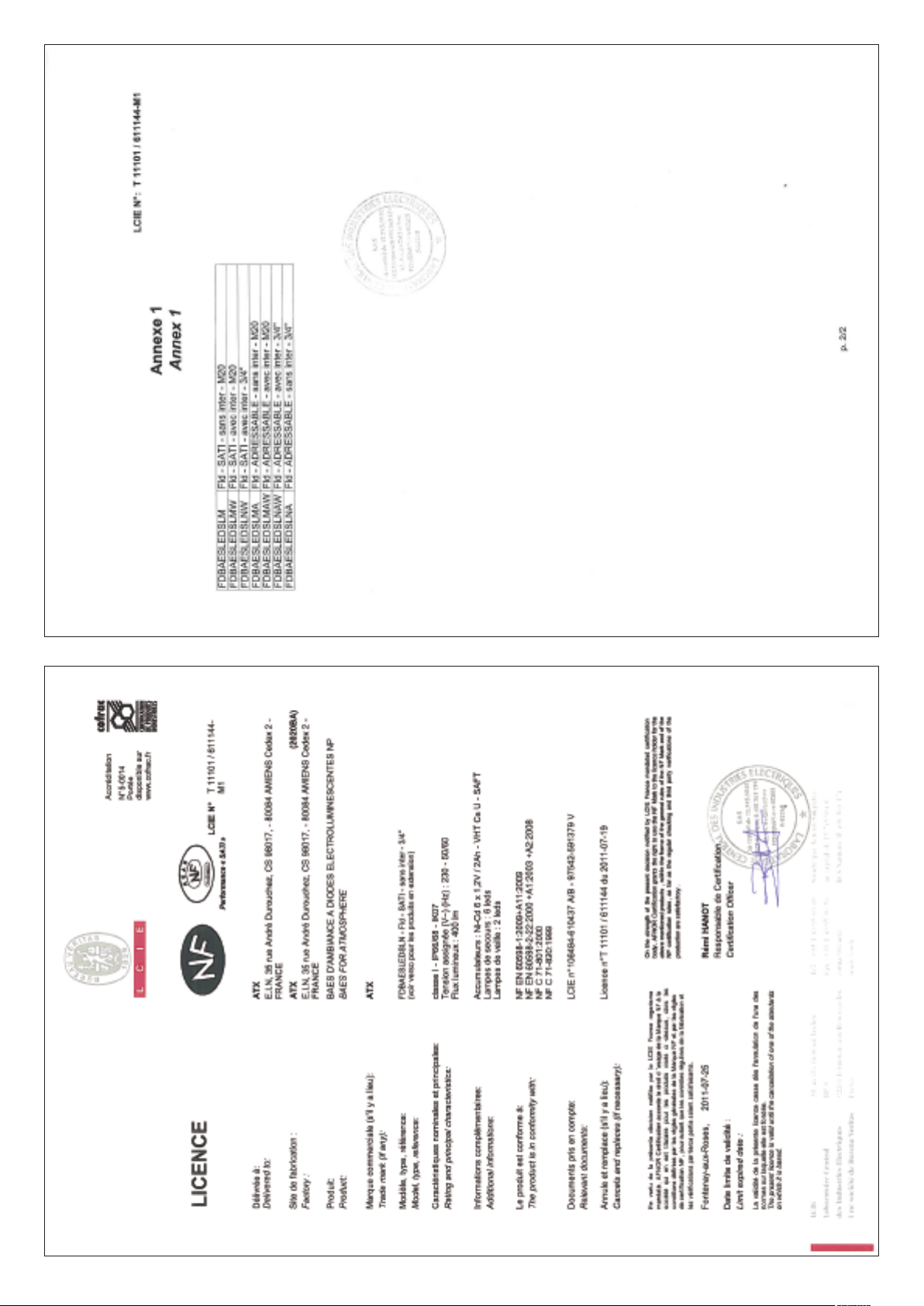
15/15
 Loading...