

Appleton Appleton Code•Master Jr. HID Factory Sealed Luminaires, 650130004 Instruction Sheet
Page 1
INSTRUCTION SHEET
Code•Master Jr.™ HID Factory Sealed Fixtures:
Explosion-Proof, Dust-Ignition-Proof.
Integrally Ballasted for H.P.S., P.S.M.H., M.H. or M.V. Lamps. For Use with Threaded Metal Conduit.
650130-004
Applications
• For use in chemical and petrochemical plants and manufacturers of plastics,
paints and thinners; in refineries; and
in other areas where ignitable vapors,
dust, moisture and corrosive elements
may be present.
• Suitable for outdoor saltwater locations and for other wet locations.
Features
• Fixtures operate safely in high ambient
temperatures.
• Patented “wireless” design. Threading
of fixture unit onto mounting hood
makes electrical connection. The only
wiring required is the attachment of
two wires to the connection block in
mounting hood.
• Connection block is easily wired: (a)
loosen two screws, (b) make wire connections, (c) re-position connection
block. (See Figure 3)
• Safe, easy servicing without disconnecting any wiring. “Wireless” fixture unit
threads off mounting hood for convenient servicing or for immediate replacement with a “stand-by” unit.
• Acme double-lead threads speed
installation and fixture removal from
mounting hood, only half as many turns
are required as for single-lead threads.
The threads do not stick or gall, eliminating problems often encountered with
single-lead threads during fixture unit
removal.
• Eight threads are always fully engaged
in an explosion-proof manner , even after
fixture unit is backed off to break the
electrical connection.
• Engineered for safety. Safe even if
current is accidentally left on because
arcing, if any, is safely confined to the
interior.
• All threaded joints are flame-tight.
• Integrally-ballasted HID lighting
fixtures; separate ballasts not required.
• Factory sealed. External seals not
required for Groups C and D.
• Fixtures for use in Group B locations
are furnished complete with UL required
sealing fitting.
• Shock-absorbing medium-base socket
mount prolongs lamp life.
CLASS I, Div. 1 & 2, Groups B,C,D
CLASS II, Div. 1, Groups E, F, G
CLASS II, Div. 2, Groups F, G
CLASS III
CAP-75B
CAS-150B
• Porcelain socket with nickel plated
phosphor bronze screw shell. Assures
trouble-free operation in high ambient
areas.
• Choice of mountings: pendant, ceiling,
bracket and stanchion.
• Fiberglass reinforced polyester reflectors in standard dome, or 30º angle
styles are ideal in installations where
luminaire is subject to exceptionally
severe corrosive atmospheres.
• Optional guards protect globes from
damage. Secured to fixture with three
stainless steel screws. (See Figure 3)
Standard Materials
• Ballast bodies and guards: copperfree aluminum (less than 4/10ths of 1%
maximum copper content).
• Pendant mounting hoods: die-cast
copper-free aluminum (less than 4/
10ths of 1%).
• Ceiling, bracket and stanchion mounting hoods: sand cast copper-free
aluminum (less than 4/10ths of 1%).
• Reflectors: fiberglass reinforced poly ester.
Standard Finishes
• Ballast bodies, guards and mounting
hoods: Epoxy powder coated finish.
Two coat baked finish, electrostatically
applied for complete uniform corrosion
protection.
CLASS I, Div. 1 & 2 Groups C, D
CLASS II, Div. 1, Groups E, F, G
CLASS II, Div. 2, Groups F, G
CLASS III
CAP-75 CAP-100
CAC-75
CALB-75
CLASS I, Div. 1 & 2 Groups D
CLASS II, Div. 1, Groups E, F, G
CLASS II, Div. 2, Groups F, G
CLASS III
CAC-100
CALB-100
CAS-150
Electrical Specifications
• Wide range of wattages and voltages.
Code-Master Jr. HID fixture with in-head
ballasts available for 35 to 175 watt
medium base lamps (35W HPS in 120V
only). 50W HPS fixtures have dual-tap
ballast (120V and 277V). All other wattages have multi-tap (120V, 208V, 240V,
277V) and 480V.
• Ballasts operate at low temperatures:
MV, PSMH, and MH — minus 20
— minus 40
• 35W through 150W high pressure
sodium ballasts are high reactance, high
power factor type.
Compliances
• UL Listed.
• UL Standard 844 and 1598A.
• Suitable for use in wet locations.
• Class I, Div. 1 and 2, Class II, Div. 1
and 2. See listing pages for specific
groups.
• Appleton aluminum products are
produced from a high strength copperfree alloy (less than 4/10ths of 1%
maximum copper content).
Options
• “Hot Restart” Emergency Option: av ailable for 35W through 150W HPS only.
F.
º
F; HPS
º
EGS Electrical Group • 800-621-1506 • www.appletonelec.com Rev. C 06/08/04 Page 1
Page 2
INSTALLATION AND MAINTENANCE INSTRUCTION
WARNING
1. Do not modify unit in any way. Modification may affect safety
and reliability.
2. Improper use or failure to follow these instructions could
result in serious injury or proper ty damage.
3. Operator should be instructed in the safe and proper usage
and maintenance of this product.
WARNING
1. Disconnect electrical power before installation, adjustment
and maintenance.
2. DO NOT overload; the amperage and voltage indicated
on the name plate must not be exceeded.
3. Check continuity before connecting electrical power.
4. This fixture intended for use with ballast suitable for lamp
type and wattage shown on fixture label.
GENERAL
ELECTRICAL
Read Carefully Before Attempting To Install Fixture
Class I, Div. 1 and 2, Groups B, C, D
Class II, Div. 1, Groups E, F, G
Class II, Div. 2, Groups F, G
Class III
UL 844, 1598A (Marine)
Suitable for use in wet locations
GROUP B INSTALLATIONS:
WARNING: This fixture is designed for permanent
installation in GROUP B classified locations (as defined
by the National Electrical Code) only when installed with
appropriate Appleton Electric Company mounting hoods.
For GROUP B installations, the mounting hood, sealing
fitting and fixture must all be marked as suitable for use in
GROUP B areas. (See Figure 1)
WARNING: Only the CAP75B 3/4” pendant hood and
the CAS150B, 1-1/2” 25¡ stanchion hood, are approved
for use in Group B locations, and the Group B markings will appear on label of the mounting hood. Mounting
hoods without the Group B marking are not acceptable for
Group B installations even if sealing fittings are used.
WARNING: Both the CAP75B and the CAS150B mount-
ing hoods must have a Group B approved sealing fitting
of the appropriate trade size installed within two inches of
the hood. Any manufacturer”s Group B approved sealing
fitting may be used. Follow the manufacturers sealing
fitting instructions for proper seal installation.
Pendant and Stanchion Hood: Remove connection
block from hood by loosening two mounting screws,
Thread hood onto conduit at least five threads (conduit
should engage the internal stop) and tighten locking set
screw. Connect the ground wire to the green screw provided in hood. Connect the b lack wire to the brass colored
screw and the white wire to the silvered colored screw on
the mounting block. Replace the connection block into the
mounting hood and re-tighten the screws securely. (See
standard assembly instructions on page 3 for remainder
of fixture installation.)
FIGURE 1
CLASS I, DIV. 1 & 2,
GROUP B INSTALLATIONS:
LABEL
NAMEPLATE
STANCHION MOUNT
CAS-150B
PENDANT MOUNT
CAP-75B
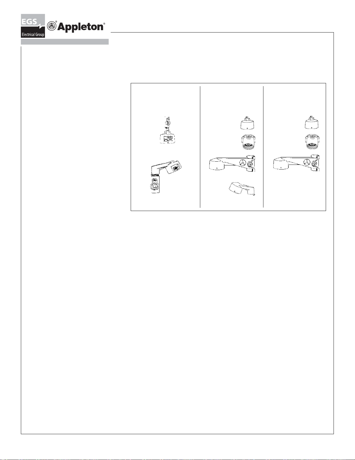
FIGURE 2
CLASS I, DIV. 1 & 2,
GROUP C, D INSTALLATIONS:
IMPORTANT: Remove all unused
CEILING
MOUNTING
HOOD
CONNECTOR
BLOCK
COLLECTOR RING
NAMEPLATE FOR
SPECIFICATIONS
IMPORTANT
FOR CORRECT CODE CLASSIFICATION AND GROUPING SEE
CHART ON PAGE 1.
AND PIN
ELECTRICAL
conduit plugs and reinstall with
pipe sealant.
SET SCREW
DOUBLE E LEAD
ACME THREADS
AS FIXTURE
UNIT IS
THREADED
INTO MOUNTING
HOOD, AN
AUTOMATIC
ELECTRICAL
CONNECTION
IS MADE
Page 2 Rev. C 06/08/04 650130-004 EGS ELectrical Group • 800-621-1506 • www.appletonelec.com
Page 3

INSTALLATION OF MOUNTING ACCESSORIES
(Not listed for Group B)
Read Carefully Before Attempting To Install Fixture
WARNING
• All mounting hoods using 3/4” conduit are Listed for Groups
C and D.
• All mounting hoods using 1” conduit are Listed for Group D
ONLY.
• 25
stanchion mount tapped 1-1/2” with 1-1/4” reducer
º
are rated for Groups C, D. (See listing on page 1)
PENDANT HOOD: See Figure 3
Remove connection block from hood by loosening two (2)
mounting screws. Thread hood onto conduit at least five (5)
threads (conduit should engage the inter nal conduit stop) and
tighten locking set screw. Connect the ground wire to the green
screw provided in hood. Connect the black supply wire to the
brass colored screw and the white supply wire to the silver colored screw on the connection block. Replace connection block
into the mounting hood and re-tighten the screws securely.
WALL BRACKET AND CEILING BOX
Install wall bracket or ceiling box on structural support member
with four bolts through four external mounting holes. Remove
connection block and connect electrically as described under
“Pendant Hood”.
STANCHION MOUNT
Remove connection block. Thread stanchion onto conduit at
least five (5) threads (conduit should engage the internal
conduit stop) and tighten locking set screw. Connect electrically
as described under “Pendant Hood”.
WARNING
• Disconnect power supply before servicing fixture.
• Failure to ground this fixture can result in an electric
shock which may be fatal.
• This fixture is designed for and should be used
permanently installed in accordance with the National Electrical
Code and all a pplicable local codes.
INSTALLATION OF FIXTURES
• Single voltage fixtures are completely wired, needing no
additional field wiring. Fixtures with multi-tap ballast (more than
one ballast voltage listed on nameplate) need to have one
ballast primary lead connected to the fixture lead.
• Verify that the supply line voltage and fixture nameplate voltages are compatible (If more than one ballast voltage is listed
on the nameplate, the fixture contains a multi-tap ballast requiring one internal connection. (See wiring diagrams Page 4)
• Verify that the hazardous groups and the fixture operating
temperatures marked on the nameplate comply with the
temperature restrictions of the hazardous area in which the
fixture is to be mounted.
• Use supply wire rated for ambient temperatures to be encountered. (See nameplate Figure 3).
Install and tighten lamp (to achieve sufficient torque) to fully
depress the sockets” center contact.
RELAMPING
T o relamp , after disconnecting the power , open fixture as described
under “REMOVE GLOBE-RING ASSEMBLY”. Remove old lamp
and install new lamp as d
and “CLOSIN
G FIXTURE”. (See page 4)
escribed under “INSTALLING LAMP”
CLOSING FIXTURE
The globe-ring must be tightened to compress gasket, this
insures watertightness. Screw the globe-ring assembly into
housing by hand until gasket makes contact. Continue to
rotate additionally past three notches or for 2” of travel. To
assist in rotating globe-ring assembly, use two screwdrivers
inserted through slots on opposite sides of ring and operate
against pry bars in housing. Lock globe-ring in place by tightening locking screw until it engages the edge of the housing.
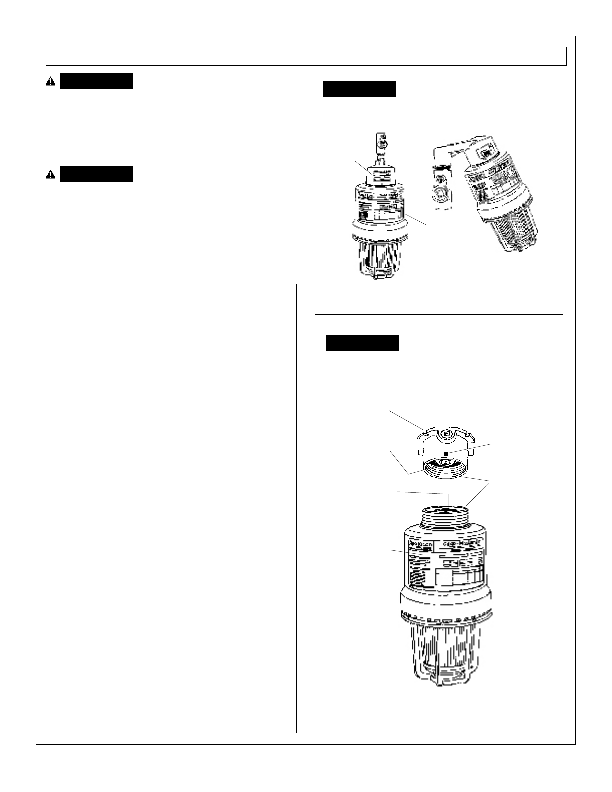
FIGURE 3
GROUND SCREW
(GREEN)
PENDANT HOOD
BLACK WIRE
CONNECTION
BLOCK SCREWS
NAMEPLATE
SOCKET PLATE
ASSEMBLY
REFLECTOR
AND GUARD
ATTACHMENT
SCREWS (3)
Pendant Mount
One Hub
SET SCREW
NAME PLATE
SET SCREW
WHITE WIRE
CONNECTION
BLOCK
DOUBLE LEAD
ACME THREADS
FIXTURE
(BALLAST)
HOUSING
MEDIUM BASE
SOCKET–35W
THRU 175W
GLOBE RING
ASSEMBLY
GUARD
Ceiling Mount
Four Hubs
Three close-up
plugs
Wall Mount
Four Hubs
Three close-up
WIRING MULTI-TAP BALLAST
• Remove globe-ring assembly. Loosen three screws securing
socket plate. Remove plate and set aside (enough slack in the
25¡ Stanchion Mount
One Hub
lead wires is provided). Locate fixture lead marked “line” and
connect to the ballast voltage lead corresponding to supply voltage. All other ballast v oltage leads must remain capped. Replace
socket support plate and tighten three screws. Replace globering assembly and tighten locking screw.
INSTALLING LAMP
Check lamp type and wattage against fixture nameplate.
CMAD-1 MOUNTING ADAPTER With Connection Block
Permits use of existing Code•Master mounting hoods(AAC
Ceiling or AALB Brackets) with the new Code•Master Jr.
fixture unit. After removing e xisting fixture unit and adapter,
screw in the CMAD-1 adapter. Then thread new fixture into
the CMAD-1. Tighten set screws.
IMPORTANT:
CMAD-1
NOT UL LISTED
EGS ELectrical Group • 800-621-1506 • www.appletonelec.com Rev C 06/08/04 650130-004 Page 3
Page 4

FIGURE 4
DESCRIPTION
Nameplate
Capacitor
Capacitor
Bracket
Heat Shield
Lamp Socket
Wiring Screws
Reflector or
Guard Screw
Globe cut-away
showing lamp
Globe
Mounting Block Assembly
Ballast Housing
Ballast
Ignitor
Ignitor
Bracket
Heat Shield
Ballast Mounting
Screws #8-32
Socket Mounting
Plate
Socket Gasket
Marine Gasket
Globe Ring
Assembly
Hex Head
Locking Screw
All statements, technical information and recommendations
herein are based upon data and tests believed to be reliable.
The accuracy or completeness of such data or test results
are not guaranteed. Pursuant to Appleton Electric Company”s
“Terms and Conditions of Sale”, because Appleton Electric neither knows nor controls the applications or conditions in which
the product will be used, the purchaser must determine the
appropriateness for the intended use and the product in such
applications or conditions
WIRING DIAGRAMS:
WIRE CONNECTOR
HX-HPF
WIRING FOR HPS AND 50-100W MH MULTI-TAP
FIGURE 5 FIGURE 6
ROTATE
ADDITIONALLY
PAST THREE
NOTCHES OR
FOR TWO (2)
INCHES OF
TRAVEL.
GUARD
ANGLE
REFLECTOR
REMOVE GLOBE-RING ASSEMBLY
• Loosen hex head locking screw (longest) in globe ring until
screw clears ballast housing. Un-thread globe-ring assembly. A
screwdriver inserted in housing notches and in globe ring slots,
will assist in removing globe-ring assembly (see figure 6). DO
NOT use glass globe to un-thread globe-ring assembly as this
might loosen the globe locking ring. (Should globe locking ring be
accidentally loosened, it should be retightened.)
INSTALLATION OF REFLECTOR AND GUARD
• Reflectors and guards are provided with keyhole slots. To install,
loosen three shorter screws in globe-ring assembly and insert
reflectors or guards over them. (Be sure slots for the locking
screw are properly located.) Tighten three screws.
• When an angle reflector is used, orient reflector to direct light
output near the desired direction. Fine tune by rotating globe-ring
assembly after loosening hex head locking screw. (See Figure 4)
• Be sure marine gasket is still under compression by slightly tightening
locking screw.
WIRE CONNECTOR
HX-HPF
WIRING FOR HPS 120V OR 480V
WIRE
CONNECTOR
CWA
WIRING FOR 100 MV AND 175W MH MULTI-TAP
WIRE
CONNECTOR
CWA
WIRING FOR 100W MV AND 175W MH 480V
Page 4 Rev. C 06/08/04 650130-004 EGS ELectrical Group • 800-621-1506 • www.appletonelec.com
 Loading...