


EGS Electrical Group • 7770 N. Frontage Rd • Skokie, Illinois 60077
Rev. C 08/28/01 Page 1
654104-000
INSTRUCTION SHEET
A-51 SERIES INCANDESCENT LIGHTING FIXTURE
INSTALLATION AND MAINTENANCE DATA SHEET
The fixture unit must be installed with one of the following
mounting hoods for safe operation. Failure to use fixture
unit with one of the following mounting hoods voids warranty as well as the U.L. Listing and creates the risk of fire or
explosion.
Fixture unit must be installed with:
DIRECTIONS FOR FIXTURE
INSTALLATION
1.Use the installation drawing as a guide.Install mounting hood
first as all wiring connections are made in the mounting
hood.The fixture unit requires no internal wiring connections.
• Install mounting hood to conduit system (and/or wall,
ceiling or stanchion). If using pendant or stanchion
mounting hood, secure the hood to the conduit system with
the set screw.
2.Remove the connection block (VPT7) from the mounting
hood by loosening (but not removing) the two Phillips head
screws.Turn connection block counter-clockwise to remove.
3.When using ceiling bracket (AAC-), long wall bracket (AALB-), o r
short wall bracket (AASB-), mounting hoods, threaded
adapter (59064050000) can be removed by lifting
gasket (59064034000) to access set screw.
• Loosen set screw and turn adapter counter- clockwise for
easier access to junction box. If long bracket (AALB-) is
being used, bracket can be removed from junction box by
loosening set screw in flange and turning counter clockwise.
4.Pull supply wires from the conduit into the junction box.Make
connection of supply wires to the VPT-7 connection block by
attaching “HOT” voltage lead to the brass terminal and
common “neutral” lead to silver terminal.
5.Secure threaded adapter (where applicable) or long
bracket (where applicable) to junction box and tighten all set
screws.
6.Secure VPT-7 connection block to threaded adapter or
mounting hood by slipping over Phillips head screws,
turning clockwise and tightening screws.
7.Install lamp into fixture unit. See directions under “Lamp
Installation Instructions”.
8.Inspect threads of mounting hoods and the fixture unit to be
sure they are clean and free of damage.
• Inspect globe for any chips, scratches or cracks.
CAUTION GENERAL
Chipped, scratched or cracked
globes will fail.Replace any
such defective lamp housing.
9. Thread the fixture unit into mating threads of
mounting hood until tight against gasket of mounting
hood. Locking spring of fixture unit should engage with
notches on mounting hood.
10. Install guard and/or reflector if desired. Check tightness of
set screws and all threaded joints. Activate supply circuit
to test fixture.
KEEP THIS MANUAL FOR FUTURE REFERENCE
A51 Series lighting fixtures for:
Class I, Division 1, Groups C and D;
Class II, Division 1, Groups E, F, and G
WARNING GENERAL
1. DO NOT MODIFY UNIT IN ANY WAY. Modification may
affect safety and reliability.
2. Improper use or failure to follow these instructions could
result in serious injury or proper ty damage.
3. Operator should be instructed in the safe and proper
usage and maintenance of this product.
WARNING ELECTRICAL
1. Disconnect electrical power before installation, adjust-
ment and maintenance.
2. DO NOT overload; the amperage and voltage indicated
on the nameplate must not be exceeded.
3. Check continuity before connecting electrical power.
4. All installations must comply with applicable local and/or
National Electrical Code.
5. Before installing check fixture unit nameplate and carton
labels to be sure you have correct fixture and mounting
hood. Circuit must be deactivated before installing fixture.
CAUTION GENERAL
1. All A-51 Series Fixtures are to be mounted vertically
with lamp base up.
AAP-50, AAP-75 or
AAP-100
Pendant Hood
AAC-50, AAC-75 or
AAC-100
Ceiling Hood
AALB-50, AALB-75
or AALB-100
Long Wall Bracket
Hood
AASB-50, AASB-75
Short Wall Bracket
Hood
FREE OF
CHIPS OR
CRACKS
EGS Electrical Group • 7770 N. Frontage Rd • Skokie, Illinois 60077
Pag e 2
654104-000 Rev. C 08/28/01
MAINTENANCE DATA
•To relamp, see “Lamp Installation Instructions.”
•To maintain maximum light output from this fixture,
it should be cleaned periodically as follows:
1. The aluminum exterior of this fixture should be
cleaned only with a mild soap or cleaner, and
should be rinsed with water immediately.
Alkaline or acidic cleaners will attack the protective
coating of epoxy on the fixture and should not be
used. This will allow the epoxy to protect the fixture
from corrosive elements in the atmosphere and
result in longer fixture life.
2. The glass globe should be cleaned using a soft
cloth and a non-abrasive cleaner. The globe
should be regularly inspected for scratches or
chips.If the globe is scratched or chipped, it must be
replaced.
3. The porcelain enamel reflector may be cleaned with
any non-abrasive detergent or glass cleaner.
• These periodic cleaning procedures are impor tant
to prevent the accumulation of dust and dirt which
will impair the light output of the fixture.
• When relamping, be careful not to damage the
external threaded areas, since they maintain the
fixture’s explosion-proof properties.
• When removing and repairing fixture, lubricate
threads only with Appleton TLC-3 conductive, high
temperature lubricant. This should only be necessary if threads are no longer coated with the blue or
black color of the dry film lubricant.
• See attached drawing for replacement parts list
OPERATIONAL DATA
•The fixture must be operated in an environment that
does not exceed 40°C.
• The fixture may be operated on AC power only up
to 300 volts.Use lamp rated for operating voltage.
WARNING:
• To reduce the risk of fire or explosion, do not install
where the operating temperature exceeds ignition
temperature of hazardous atmospheres.
• Refer to the nameplate on the fixture for maximum
operating temperature and for proper fixture
classification.
9
NOTE:All installations must comply with applicable local
and/or National Electrical Code.
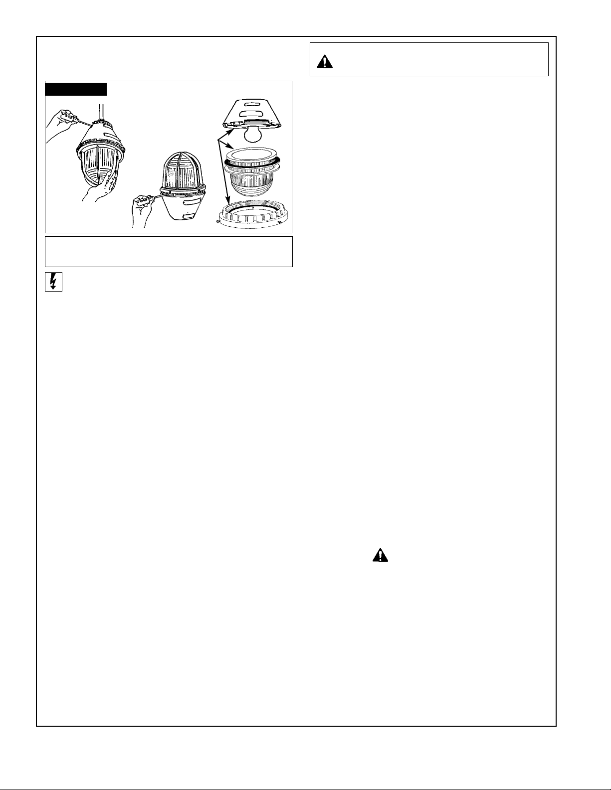
• A lamp may be safely and easily installed into
the fixture at a work bench.
1. Disconnect fixture from supply circuit.
2. Remove fixture unit from mounting hood by insert-
ing screw d ri ver into canopy notches and
using release lugs for leverage.
•Once loosened from mounting hood, fixture unit can
be quic kly unscre w ed b y hand.Do not remove fixture
unit from mounting hood under load.
3. Place fixture unit on bench with globe side up.
4. Remove globe ring using pry notches if necessary.
5. Remove aluminum and fiber gaskets.
6. Lift globe carefully off of fixture and place safely on
clean surface.
7. Refer to fixture nameplate for proper lamp wattage
and types.
8. Inspect globe for chips or scratches as such def ects
will result in globe failure.
9. Wipe ground surface of globe and mating surf ace of
fixture with soft clean cloth to eliminate dust, oil or
grit.
10. Carefully place globe back on ground surface of
fixture unit.
11. Place the fiber gasket on globe flange first, then
place aluminum gasket on top of fiber gasket.
•This sequence is important for safe operation
of fixture.
12. Replace globe ring carefully and screw onto fixture
unit until globe ring is tightly in place.
13. Thread fixture unit into mounting hood as per “Directions
for Fixture Installation, Numbers 9 and 10”.
LAMP INSTALLATION
INSTRUCTIONS
CAUTION: All A-51 series fixtures are to be mounted
vertically with lamp base up.
CAUTION :
Disconnect supply circuit
before opening or relamping fixture.
➁
FIGURE 1

EGS Electrical Group • 7770 N. Frontage • Skokie, Illinois 60077
654104-000 Rev. C 08/28/01 Page 3
LONG BRACKET INSTALLATION
1. Remove bracket from junction box, pull through
leads to connector block. Attach ground wire
to grounding screw.
2. Remove Connector block from threaded adapter,
p
ull leads through to connect wires t
o cor-
rect terminal screws.
3. Push block into place and tighten screws —
Install fixture. NOTE: Plugs should be removed
and resealed with pipe sealant.
FIGURE 1
#10-24x3/8"
SL.RD.HD.
SET
SCREW
59064050000
THREADED ADAPTER
VPT-7 CONNECTOR BLOCK
SCREW #8 -32X1/2" PH. HD.
JUNCTION
BOX
TLC-3 HERE
A-51 GROUPS C & D LIGHTING FIXTURES FAMILY TREE
MOUNTING HOODS (Use of components marked “Not U.L. Listed” voids the U.L. Listing of the assembled fixture.)
Pendant Ceiling 25° Stanchion Long Bracket 15° Short Bracket
0ne Hub Three close-up plugs One close-up plug. Three close-up plug One close-up plug.
1/2" AAP-50 1/2" AAC-50 1-1/2" AAN-150 1/2" AALB-50 1/2" AASB-50
3/4" AAP-75 3/4" AAC-75 (Not U.L. Listed) 3/4" AALB-75 3/4" AASB-75
LAMP HOUSING
MED. BASE LAMP
200/300W (PS30)
AAU-2NS
LAMP HOUSING
MED. BASE LAMP
150-300 (A-
23)(PS-25)
AAU-15N
LAMP HOUSING
MED. BASE LAMP
100W(A-21)
AAU-1N
LAMP HOUSING
MOGUL. BASE LAMP
500W (PS-40)
AAU-5NS
LAMP HOUSING
MOGUL. BASE LAMP
500W (PS-40)
AAU-4MVNS
ALUMINUM GUARD
AAGU-2
ALUMINUM GUARD
AAGU-5
ALUMINUM GUARD
AAGU-4MV
PORCELAIN
REFLECTOR
STANDARD DOME
AARW-2ST
PORCELAIN
REFLECTOR
30° ANGLE
AARW-2AN
POLYESTER
REFLECTOR
STANDARD DOME
AARP-2ST
(Not U.L. Listed)
POLYESTER
REFLECTOR
30° ANGLE
AARP-2AN
(Not U.L. Listed)
PORCELAIN
REFLECTOR
STANDARD DOME
AARW-5ST
ALZAK ALUMINUM
REFLECTOR
HIGH BAY
AARE-2HB
PORCELAIN
REFLECTOR
30° ANGLE DOME
AARW5AN
ALZAK ALUMINUM
REFLECTOR
HIGH BAY
AARE-5HB
THREE-WAY EXIT SIGN
IN PLACE OF GUARD
CJEXRN
(Not U.L. Listed)
ALUMINUM GUARD
AAGU-1
PORCELAIN
REFLECTOR
STANDARD DOME
AARW-15ST
PORCELAIN
REFLECTOR
30° ANGLE
AARW-15AN

EGS Electrical Group • 7770 N. Frontage Rd • Skokie, Illinois 60077
Pag e 4
654104-000 Rev. C 08/28/01
Dimensions: A-51 Incandescent Lighting Fixtures.
A-51 Series Reflectors
STD. DOME 30° ANGLE HIGH BAY
Size Watts AB A B A B
60-100 12.00 4.50 10.00 7.63 — —
150-200 14.00 4.38 10.00 7.63 — —
200-300 16.00 5.19 12.00 7.88 12.00 6.06
300-500 20.00 6.84 18.00 13.13 18.00 9.13
STANDARD DOME 30° ANGLE HIGH BAY
Dimensions in Inches
Stanchion Pendant Ceiling Long Bracket Short Bracket
Size (Watts) A B CAB C AB CABC AB C
60-100 11.47 10.85 11.50 12.25 11.63 7.06 13.75 13.13 7.06 13.75 13.13 12.38 13.56 12.94 9.13
150-300 11.47 10.85 11.50 12.25 11.63 7.06 13.75 13.13 7.06 13.75 13.13 12.38 13.56 12.94 9.13
200-300 13.07 12.38 12.71 13.94 13.25 8.81 15.44 14.75 8.81 15.50 14.75 13.25 15.19 14.50 10.13
300-500 15.09 14.34 14.64 16.00 15.25 12.13 17.50 17.75 12.13 17.50 16.75 14.88 17.25 16.50 11.94
2.69"
(6.8cm)
B
C
 Loading...