

504851-000 INSTRUCTION SHEET
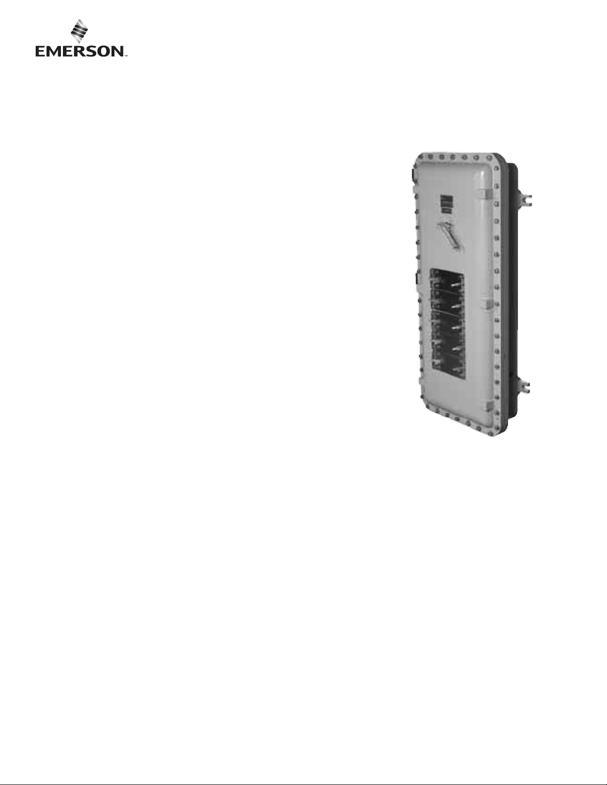
Appleton™ ALPN/ALPF/APPN/APPF Explosion-Proof Panelboard
Instruction Manual
RETAIN THIS INSTRUCTION SHEET FOR FUTURE REFERENCE. For safe installation and
operation, please read these instructions carefully and with full understanding.
Signal Words Defined
DANGER indicates a hazardous situation which, if not avoided, will result in death or
serious injury. WARNING indicates a hazardous situation which, if not avoided, could
result in death or serious injury. CAUTION indicates a hazardous situation which, if not
avoided, could result in minor or moderate injury. NOTICE is used to address practices
not related to physical injury.
1.0 SCOPE
• This manual contains general information with regards to description, installation and
maintenance of EGS ALPN/ALPF Series Explosion Proof Panelboards, for up to fortytwo branch circuit breakers. It does not cover special modications, additions
or deletions, other than those listed in the catalogue.
• More specic information, if required, can be obtained by contacting the EGS Sales
representative in your area.
2.0 INSTALLATION
2.1 Mounting
The ALPN/ALPF Series panelboard is intended to be mounted vertically. Provided for this
purpose are four mounting feet with keyhole slots, sized to accommodate 3/8” bolts. For
mounting centers, see Section 6.1.
2.2 Wiring
Wire after mounting.
Open cover by loosening all cover bolts; do not remove bolts as they are captive to the cover. Supply circuit is wired into the main
panel lugs or main circuit breaker. A main ground lug is provided for system ground. For panelboards that are prewired (ALPF or
APPF), supply circuit connections are made in the top/bottom box main terminals.
2.2.1 Standard Breaker
Load circuit line goes to breaker, load circuit neutral to panel neutral bar, load circuit ground to ground bar.
2.2.2 GFI Breaker
Load circuit line and neutral go to breaker, load circuit ground to ground bar, breaker neutral to panel neutral bar. (See gure 6.4)
2.2.3 GFI Breaker with Alarm Contact
Load circuit line and neutral go to breaker, load circuit ground to ground bar, breaker neutral to panel neutral bar, alarm contact
leads to external enunciator. (See gure 6.4)
504851-000 Rev. A 02/07/19 • Page 1 of 6

3.0 MAINTENANCE
3.1 Flange/Cover Closure
After each opening and before each closure of the cover, the anges of both box and cover must be wiped clean of any dust, dirt or
metal particles which may prevent complete and tight closure of the unit. Enclosure ange should be oiled or greased. Failure to do so
may result in an explosion hazard. During normal operation, ensure that all cover screws are installed and kept tight. Failure to do so
may result in an explosion hazard.
3.2 GFI Breaker Testing
Each GFI breaker in the panel must be tested monthly to ensure maximum protection against electrical shock hazard. The date of
this test should be recorded on an appropriate record sheet, posted in a conspicuous place on or adjacent to the panel. Test record
stickers are supplied with the panel.
3.3 Parts Replacement
Before replacing any parts of the panel, which may require opening of the cover, ensure that the power to the panel mains
is locked off.
3.3.1 Standard Breaker
Disconnect the load circuit line from the breaker; replace with appropriate breaker supplied by EGS or Cutler Hammer. Reconnect
as per Section 3.2.1.
3.3.2 GFI Breaker
Disconnect the load circuit line and neutral line from the breaker and breaker neutral from the panel neutral bar; replace with
appropriate breaker supplied by EGS or Cutler Hammer.
Reconnect as per Section 3.2.2.
3.3.3 GFI Breaker with Alarm Contact
Disconnect the load circuit line and neutral line from the breaker, breaker neutral from the panel neutral bar and alarm contact
leads from the external enunciator leads; replace with appropriate breaker supplied by EGS or Cutler Hammer. Reconnect as per
Section 3.2.3.
3.4 Cleaning
The exterior of the panel may be washed with water and mild soap solution. Avoid abrasives which may damage the nish, especially
on the Lexan circuit directory card shields or Lamacoid operator cover or legend plates.
4.0 OPERATION
4.1 Breaker
The status of the breaker is determined by the position of the knob as indicated by the label at the top of the column of operators.
Operation is as simple as twisting the knob to the desired position. (See g. 6.2)
NOTE: After closing panel door, whether during initial installation or after maintenance be sure to TWIST or PULL and TWIST (for
APPN/F) exterior actuator to ensure proper mechanical interface between exterior actuator and internal breaker toggle. See Panel
Board Actuator Instruction Sheet.
CAUTION: Never try to defeat a LOCKED OUT breaker.
4.2 GFI Test Button
The GFI breaker test is performed by depressing the test button adjacent to the GFI breaker. A positive test will put the breaker in
tripped condition. Reset the breaker to resume normal operation.
4.3 Resetting Tripped Breakers
Resetting is accomplished by rst turning the breaker OFF, and then ON again. A tripped breaker cannot be turned ON before it
is RESET. If it cannot be turned ON, it is either not RESET, or it is being subjected to conditions which cause an immediate trip.
Investigate Circuit.
4.4 Heater
The heater is factory pre-wired to the panel interior main and neutral lugs. It sometimes can be wired through a fuse. Heater operation
is automatic.
504851-000 Rev. A 02/07/19 • Page 2 of 6

5. 0 PREVENTIVE MAINTENANCE PLAN FOR ALPN/ALPF PANELBOARDS
The following is a recommended Preventive Maintenance Plan to ensure that the ALPN/ALPF Panel Board continue
to function properly.
• Turn power off to Panelboard and Lockout.
• Open panel board and clean both ange of enclosure and door with a soft cloth and solvent (e.g., kerosene) to remove any dirt and
dried machine oil. Never use a tool to clean ange.
• Inspect ange surface to ensure there are no gouges or ssures.
• Inspect seal gasket and replace if necessary. The gasket should free of any nicks and not be torn. There should be no gap where
the ends meet. (Most likely the gasket will be at and it is recommended to have it changed when PM is performed.)
• Inspect Breather and Drain for corrosion and if replacement is necessary order correct Breather and Drain for either a 3R or 4X
Panelboard (type found on Rating Plate).
• Inspect and ensure the inside of panelboard is clean and remove any loose particles.
• Inspect all breakers and wire connections and tighten any that may be loose due to vibration.
• Operate each breaker manually to verify the toggle operates properly without tripping
• Before closing Panelboard ensure that machine oil has been applied to ange of the enclosure. (e.g., Esso EXXCUT 235)
• After door is bolted test Gap between door and ange with feeler gauge.
• Maximum gap requirement is 0.04mm (0.0015").
• Twist or PULL and twist each exterior actuator to ensure proper mechanical interface with toggle of breaker
• It is recommended that when GFI Breakers are included in the Panelboard that they be included in the Monthly PM Test Plan; see
Test Record attached to inside of door.
• For service parts and repairs, see Installation Manual.
5.5 Panelboard Actuator Instruction Sheet
Whenever work is done that requires opening of the panelboard, be sure to turn the panelboard's main breaker or power source to the
panelboard OFF prior to opening the cover.
Instructions for handle alignment after cover have been opened.
1. Ensure both breaker and actuator is in the OFF position.
2. Close cover and verify breaker can be turned ON and OFF.
3. If the handle spins freely, the actuator is not engaged properly with the breaker.
4. Rotate handle in either direction until it stops.
5. Pull lever up and turn slightly in the direction of the stop to 4 engage breaker toggle.
6. Verify proper operation of handle.
Instructions for locking out a circuit required for maintenance.
1. Turn breaker to the OFF position.
2. Place locking device through opening in the lockout plate.
3. Perform voltage verication ON circuit to ensure circuit is OFF.
4. Perform maintenance as required.
5. Upon completion of maintenance, remove locking device from the proper circuit.
6. Turn handle to ON position.
WARNING: Never try to defeat or bypass a locked out circuit. Serious injury or death can occur.
504851-000 Rev. A 02/07/19 • Page 3 of 6

6.0 DIMENSIONAL DATA
504851-000 Rev. A 02/07/19 • Page 4 of 6

504851-000 Rev. A 02/07/19 • Page 5 of 6

Except as expressly provided by Appleton Grp, LLC (Appleton), Appleton products are intended for ultimate purchase by industrial users and for operation by persons trained and experienced in the use and maintenance of this equipment
and not for consumers or consumer use. Appleton warranties DO NOT extend to, and no reseller is authorized to extend Appleton’s warranties to any consumer.
While every precaution has been taken to ensure accuracy and completeness in this manual, Appleton Grp, LLC. assumes no responsibility, and disclaims all liability for damages resulting from use of this information or for any errors or
omissions. Specications are subject to change without notice. The Appleton and Emerson logos are registered in the U.S. Patent and Trademark Ofce. All other product or service names are the property of their registered owners.
©2019 Appleton Grp, LLC. All rights reserved.
504851-000 Rev. A 02/07/19 • Page 6 of 6
 Loading...