

Page 1

31
DIGITAL MULTIMETER
6
INSTRUCTION MANUAL
APPA 98II
Page 2

1
#
WARNING
THESE SERVICING INSTRUCTIONS ARE FOR USE BY QUALIFIED PERSONNEL ONLY.
TO AVOID ELECTRIC SHOCK, DO NOT PERFORM ANY SERVICING OTHER THAN THAT
CONTAINED IN THE OPERATING INSTRUCTIONS UNLESS YOU ARE QUALIFIED TO DO SO.
Page 3

2
INTRODUCTION
1-1 Unpacking and Inspection
Upon removing your new Digital Multimeter from its packing, you should have the following items:
1. Digital Multimeter.
2. Test lead set (one black, one red).
3. Instruction manual.
4. Protective holster.
Page 4

3
1-2 Meter Safety
Terms as Marked on Equipment.
# ATTENTION — Refer to manual.
1 DOUBLE INSULATION — Protection Class Ⅱ.
" DANGER — Risk of electric shock.
Symbols in this Manual.
# This symbol indicates where cautionary or other information is found in the manual.
FUSE
Battery
Page 5

4
1-3 Front Panel
Refer to Figure 1 and to the following numbered steps to familiarize yourself with the meter’s front panel controls
and connectors.
1. Digital Display — The digital display has a 4000 counts LCD readout with 82 segments analog bar graph, auto
polarity, decimal point, “ “ AC, DC RANGE, APO and unit annunciators.
2. Rotary Switch — Select the Function and Range desired.
3. COM Input Terminal — Ground input connector.
4. VΩ Hz Input Terminal — Positiv
e input connector for Volts, Ohms Capacitance and Temperature Frequency.
5. mA Input Terminal — Positive input connector for Amp measurements (up to 400mA).
6. A Input Terminal — Positive input connector for Amp measurements (up to 10A).
7. Range Switch, (Manual Range) — “Range” switch is pressed to select manual ranging and to change ranges.
When pressed the “Range” annunciator is displayed. Consecutively press ing the “Range” switch allows selection of the appropriate range for meas urement. To return to “Autoranging” press the “Range” switch and hold
simultaneously for 2 seconds.
Page 6

5
8. Blue Switch — Press the switch to toggle between AC Voltage / Current and DC Voltage / Current in the
Voltage / Current mode or to toggle between Resistance and continuity and diode in Ω/ /:
mode or to toggle between Frequency and RPM in Hz/RPM mode.
9. Hold Switch — This switch is used to hold the measured value for all functions, when pressed the “ “
annunciator is displayed. Conversions are made but the display is not updated.
This switch could be used in “MIN/MAX” mode or “PMIN/MAX” mode.
10. % Hz Switch — This switch is used to quickly view the frequency during measuring the AC voltage or current.
Press “ % Hz “ switch once the LCD is changed to display frequency. Push “ % Hz “ switch
again, the LCD back to display the AC signal amplitude reading. In “ % Hz “ mode, pressing
RANGE key switch does not change the frequency range. However , the RANGE key switch
changes the sensitivity of frequency detection, if the input signal amplitude is less than 5% of
full scale range, the user shall increase the sensitivity. Pressing Range switch in “ % Hz “
mode also changes range of the original voltage or current mode.
Page 7

6
Figure 1
Page 8

7
SPECIFICATIONS
2-1 General Specifications
Display : The Liquid Crystal Display (LCD) has a maximum reading of 4000 and 82 segments bar graph.
Polarity Indication : Automatic, positive implied, negative indicated.
Overrange Indication : “OL” or “-OL”.
Low Battery Indication : “ “ is displayed when the battery voltage drops below operating voltage.
Sampling : 2 times/sec for digit. 12 times/sec for analog bargraph.
Auto Power Off : Approx 30 minutes.
Operating Ambient : 0℃ ~ 30℃ (≦80%R.H), 30℃ ~ 40℃ (≦75%R.H),
40℃ ~ 50℃ (≦45%R.H).
Storage Temperature : -20℃ to 60℃ , 0 to 80% R.H. when battery removed from meter.
Temperature Coefficient : 0.15 x (Spec.Acc’y) / ℃, <18℃ or > 28℃ .
Power Requirements : Standard 9V battery NEDA 1604, IEC6F22, JIS006P.
Battery Life : Alkaline 300 hours.
Page 9

8
Dimensions (W x H x D) : 88mm x 180mm x 33.5mm , without holster.
94mm x 188mm x 40mm , with holster.
Accessories : Protective Holster , Battery (installed), Test leads and Instruction Manual.
2-2 Environmental Conditions
Indoor use.
Maximum Altitude : 2000 Meter.
Installation Category : IEC 1010, 1000V Cat.Ⅱ, 600V Cat.Ⅲ.
Pollution Degree : 2
Page 10

9
2-3 Electrical Specifications
Accuracy is ± (% reading + number of digits) at 23°C ± 5°C , less than 80% R.H.
(1) DC Volts
Range Resolution Accuracy
Over voltage
protection
400mV 100µV
±(0.25%reading + 5digits)
DC 1000V
40V 10mV
±(0.25%reading + 1digit) 400V 100mV
1000V 1V
4V 1mV
±(0.4%reading + 1digit)
Input Impedance : 10MΩ . (over 1000MΩ in 400mV range).
Page 11

10
(2) AC Volts
Input Impedance : 10MΩ // less than 100pF.
1. ±(1.5% reading + 5digits) for (50% ~ full scale) of range.
2. Frequency Response : 40Hz ~ 500Hz .
3. Frequency Response : 50Hz ~ 60Hz.
AC Conversion Type : AC conversions are ac-coupled, true rms responding, calibrated to the rms value sine
wave input.
Range Resolution Accuracy Over voltage protection
±(2.0%reading + 10digits)3
750V rms
±(1.3%reading + 5digits)1
40Hz to 1KHz
400mV 0.1mV
40V 10mV
400V 100mV
750V 1V
4V 1mV
±(1.3%reading + 5digits)
1 2
Page 12

11
Crest Factor : +1.5% addition error for C.F. from 1.4 to 3 where C.F. = Peak
+3.0% addition error for C.F. from 3 to 4 RMS
(3) DC Current
Range Resolution Accuracy Voltage Burden
±(0.6%reading + 2digits) 200mV max
±(0.7%reading + 2digits) 2V max
±(1.0%reading + 3digits) 2V max
40mA 10µA
400mA 0.1mA
10A 10mA
Overload Protection : 1A (500V) fast blow fuse (10KA breaking capacity @ 440Vac) for mA input.
(size 32 × 6.3 mm)
10A (500V) fast blow fuse (10KA breaking capacity @ 440Vac) for A input.
(size 32 × 6.3 mm)
Page 13

12
(4) AC Current
Range Resolution Accuracy Voltage Burden
±(2.0%reading + 5digits)
200mV max
2V max
±(2.5%reading + 5digits) 2V max
40mA 10µA
400mA 0.1mA
10A 10mA
Frequency Response : 40Hz ~ 1KHz.
Overload Protection : 1A (500V) fast blow fuse (10KA breaking capacity @440Vac) for mA input.
(size 32×6.3mm)
10A (500V) fast blow fuse (10KA breaking capacity @440Vac) for A input.
(size 32×6.3mm)
AC Conversion Type : AC conversions are ac-coupled true rms responding, calibrated to the rms value sine
wave input.
Crest Factor : +1.5% addition error for C.F. from 1.4 to 3 C.F. = Peak
+3.0% addition error for C.F. from 3 to 4 RMS
Page 14

13
(5) Resistance
Range Resolution Accuracy
Overload
Protection
±(0.7%reading + 3digits)
600V rms
±(0.4%reading +3digits)
±(0.6%reading + 3digits)
±(1.5%reading + 5digits)
400Ω
0.1Ω
4KΩ 1Ω
40KΩ 10Ω
400KΩ 100Ω
4MΩ 1KΩ
40MΩ 10KΩ
Open circuit Voltage : -1.3V approx.
Page 15

14
(6) Diode Check and Continuity
Range Resolution Accuracy
Max. Test
Current
Max. Open
Circuit Voltage
1mV
±(1.5%reading + 5digits)*
1.5mA 3V
* For 0.4V ~ 0.8V.
Overload Protection : 600V rms max.
Continuity : Built-in buzzer sounds when resistance is less than 30Ω approximately.
Page 16

15
(7) Frequency / RPM
Range Resolution Sensitivity Accuracy
Overload
Protection
4.0KHz/40KRPM 1Hz/30RPM
100mV rms
Frequency :
0.01% ± 1digit
RPM :
0.01% ± 10digits
600V rms
40KHz/400KRPM 10Hz/300RPM
400KHz/4MRPM 100Hz/3KRPM
4MHz/40MRPM 1KHz/30KRPM 250mV rms
40MHz/400MRPM 10KHz/300KRPM 1V rms
Page 17

16
(8) Capacitance
Range Resolution Accuracy Overload Protection
4nF 1pF
±(3%reading + 10digits)
600V rms
40nF 10pF
400nF 100pF
4µF 1nF
40µF 10nF
400µF 100nF
* 4mF 1µF
** ±(5%reading + 20digits)
* 40mF 10µF
* ±(2%reading + 8digits)
* 4mF and 40mF ranges may have rolling within accuracy.
** specify reading < half full scale of range.
Page 18

17
(9) VAHz
Function Range Sensitivity Accuracy
ACV
400mV
40mV rms
0.01%reading + 5digits
4V
0.2V rms
40V 2V rms
400V 20V rms
750V 200V rms
40mA 8mA rms
400mA 80mA rms
10A 8A rms
ACA
Page 19

18
(10) Auto Power Off (APO)
The APO sign on the LCD panel indicates the meter is working in the Auto Power Off mode. If the meter idles
for more than 30 minutes, the meter automatically turns the power off. When this happens, the state (non-
logic measurement) of the meter is saved, the meter can be turned back on by pressing any switch or
changing the rotary switch. If the meter is Re-Powered by pressing a switch, the LCD displays the saved
state, press the Hold switch to disable the hold state. The meter will alarm 15 seconds before automatically
turning power off , any key press or rotary change will reset Auto-Power-Off.
(11) Disable Auto Power Off
In order to disable auto power off function, power up the meter whilst pressing down any switch other than the
“HOLD” of BLUE switch.
Page 20

19
OPERATION
This instrument has been designed and tested in accordance with IEC Publication 1010, Safety Requirements for
Electronic Measuring Apparatus and has been supplied in a safe condition. This instruction manual contains some
Information and warnings which have to be followed by the user to ensure safe operation and to retain the instrument in safe condition.
3-1 Preparation and Caution before Measurement
1. Before measurement, warm up for at least 60 seconds.
2. When the rotary function selector is changed during measurement, be sure do so only after removing the test
leads from the equipment.
3. If the equipment is used near noise generating equipment, be aware that may become unstable or indicate
large errors.
4. # Maximum rated voltage to earth for voltage and current measurements terminals is 1000V CAT.Ⅱ, 600V
CAT. Ⅲ .
Page 21

20
3-2 Voltage Measurements
1. Connect the red test lead to the “VΩHz” input terminal and the other (black) test lead to the “COM” terminal.
2. Set the rotary function to the V ' position.
3. Measurement of AC voltage can be performed by pushing the “BLUE” key switch.
#
WARNING
TO AVOID ELECTRICAL SHOCK, HAZARD OR DAMAGE TO METER, DO NOT A ATTEMPT TO
MEASURE VOLTAGE THAT MIGHT EXCEED 1000V ms. DO NOT APPLY MORE THAN 1000V rms
BETWEEN THE COMMON INPUT TERMINAL AND EARTH GROUND.
NOTICE
UNSTABLE DISPLAY MAY OCCUR ESPECIALLY AT 400mV RANGE, EVEN THOUGH YOU DON’T
PUT TEST LEADS INTO INPUT TERMINALS. IN THIS CASE, IF AN ERRONEOUS READING IS
SUSPECTED, SHORT THE “VΩHz” TERMINAL AND THE “COM” TERMINAL, AND MAKE SURE
THE DISPLAY IS AT ZERO.
Page 22

21
3-3 Current Measurement
1. Connect the red test lead to “mA” terminal and the other (black) test lead to “COM” terminal, or use the “A” and
“COM” terminal in the 10A range.
2. Set function selector rotary switch to “ mA ” or “ A ” .
3. Measurement of AC current can be performed by pushing the “BLUE” switch.
4. Connect the test leads to the circuit to be measured.
3-4 Resistance Measurement
1. Connect the red test lead to the “ VΩHz” terminal and the other (black) test lead to the “COM” terminal.
2. Set the rotary function selector to “Ω : ” position to measure the resistance.
3. For correct reading, ensure that the device being tested contains no voltage.
4. Connect the test leads across the resistor to be measured. In order to ensure the best accuracy in measure ment of low resistance, short the test leads before measurement and note the test probe resistance. This value
must be subtracted from any subsequent circuit resistance measurements.
Page 23

22
3-5 Continuity Check by Internal Sounder
1. Connect the red test lead to the “ VΩHz” terminal and the other (black) test lead to the “COM” terminal.
2. Set the rotary function selector to “Ω : ” position.
3. Connect the test leads to the circuit to be measured. The internal sounder will operate if the resistance of the
circuit measured is lower than 30Ω approximately.
3-6 Diode Check
1. Set the rotary switch at “Ω : ” position.
2. Connect black test lead to “COM” terminal and red lead to “ VΩ Hz ” input terminal.
3. Connect test leads to the diode. Normally the forward voltage drop of good silicon diode is shown between
0.400V and 0.900V. If the diode under test is defective. “0.000” (short circuit) or “OL” (non-conductance) is
displayed. During reverse check of a diode, the diode under test is defective if “0.000” or other values are
displayed.
Page 24

23
3-7 Hz / RPM Measurement
1. Connect the red test lead to the “ VΩ Hz ” terminal and the other (black) test lead to the “COM” terminal.
2. Set the rotary function selector to “Hz RPM” position to measure the frequency or RPM.
3. Connect the test leads to the circuit to be measured.
3-8 Capacitance Measurement
1. Connect the red test lead to the “ V ΩHz ” terminal and the other (black) test lead to the “COM” terminal.
2. Set the rotary function selector to “ ” position to measure capacitance.
3. Connect the test leads to the circuit to be measured.
4. In order to ensure the best accuracy in measurement of low capacitance, to memorize the stray capacitance of
open test leads in mind to subtract from reading.
Page 25

24
MAINTENANCE
#
WARNING : TO AVOID ELECTRICAL SHOCK REMOVE TEST LEAD BEFORE OPENING THE COVER.
4-1 General Maintenance
1. Repairs or servicing not covered in this manual should only be performed by qualified personal.
2. Periodically wipe the case with a dry cloth and detergent do not use abrasives or solvents.
4-2 Battery Installation or Replacement
The meter is powered by one 9V battery. Refer to Figure 2 and use the following procedure to replace the battery:
1. Disconnect the test leads and turn the meter off. Remove the test leads from the front terminals.
2. Position the meter face down. Unscrew the battery cover screw (i).
3. Lift the edge of the battery cover (ii) until it gently unsnaps from the case top.
4. Lift the battery from the battery compartment and carefully disconnect the battery connector leads.
5. Snap the battery connector leads to the terminals of a new battery and reinsert the battery into the battery
compartment.
6. Replace the battery cover and make sure that the battery leads do not become pinched between the
case bottom and case top.
Page 26

25
Figure 2
Screw (i)
Battery Cover (ii)
9V Battery
Page 27

26
4-3 Fuse Replacement
Refer to Figure 3 and the following procedure to examine or replace the meter’s fuse:
1. Perform steps 1 though 3 of the battery replacement procedure.
2. Than remove the two screws from the case bottom and lift the case bottom until it gently unsnaps from the case
top.
3. Remove the defective fuse by gently prying one end of the fuse loose and sliding the fuse out of the fuse holder.
4. Install a new fuse of same size and rating. Make sure the new fuse is centered in the fuse holder.
5. Replace the case top and case bottom and battery cover. Make sure that the battery leads do not become
pinched between the case halves. Reinstall the three screws.
Page 28

27
Radid Fuse 1A (500V),
10KA capacity @ 440 Vac
Top Case
Bottom Case
Fuse size is 32mm x 6.3mm
10KA capacity @ 440 Vac
Radid Fuse 16A (500V),
Rapid Fuse 10A (500V),
10KA capacity @ 440 Vac
Rapid Fuse 1A (500V),
10KA capacity @ 440 Vac
Fuse size is 32mm x 6.3mm
Figure 3
Page 29
28
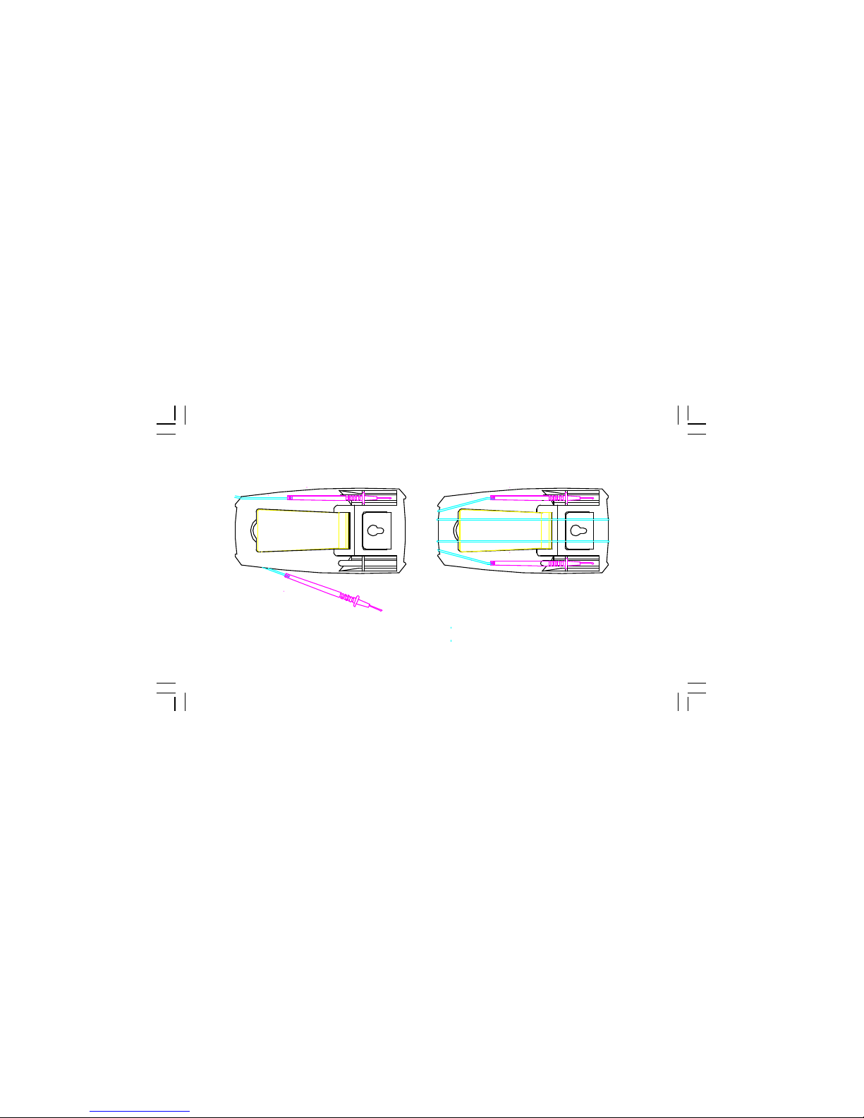
Clip one probe on the holder for
one handed meter operation.
Wrap the leads around the holster
to store the test probes.
HOW TO USE THE PROBE HOLDER
Page 30
29
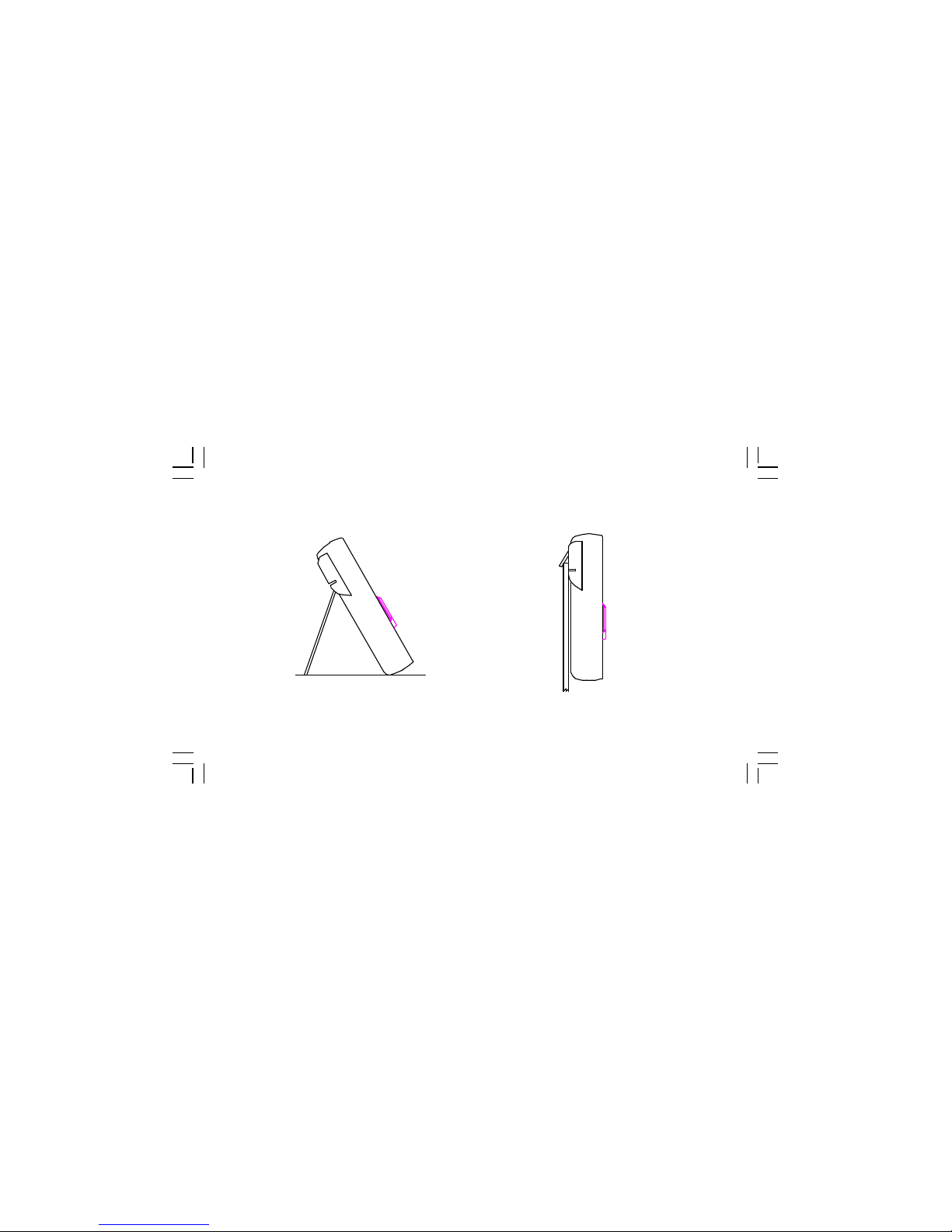
HOW TO USE THE PROBE HOLDER
Swing the stand out for easier meter reading. Swing the upper holder out and hook it over a door.
Page 31
30
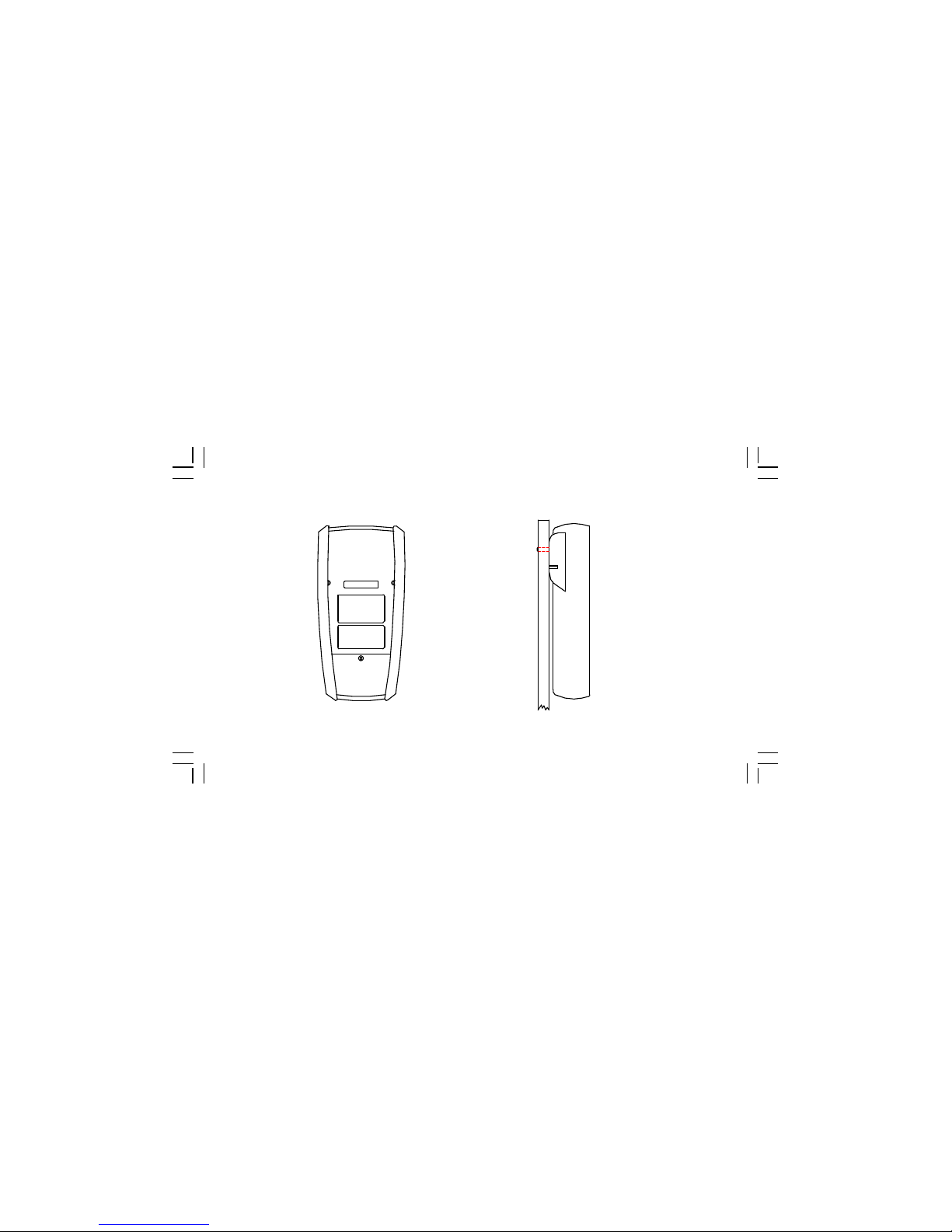
HOW TO USE THE TILT STAND AND HOLSTER
Meter in holster face down. Hang on nail at workbench.
Page 32

APPA TECHNOLOGY CORP.
9F.119-1 Pao-Zong Rd., Shin-Tien,
Taipai, 23115, Taiwan, R.O.C.
P.O.Box. 12-24 Shin-Tien, Taiwan.
Tel : 886-2-9178820 Fax : 886-2-9170848
e-mail:info @appatech.com
http://www.appatech.com
Printed In Taiwan
Copright 3 2003, APPA Tech., Corp. All rights reserved.
 Loading...