


39214- 304/ Iss ue 2
AlarmSense® Installation Guide
General
AlarmSense® is a range of conventional detection and alarm products designed to be connected to the same pair of supply wires. It is not compatible with other ranges of detectors
and must be used with AlarmSense compatible control equipment.
The AlarmSense Sounder Base, Sounder Beacon Base and Alarm Relay referred to in this
guide incor porate priority/non-priority switching. If this enhanced feature is required,
please check with the control equipment manufacturer that the feature is accessible.
The basic functions of all these devices are compatible with all AlarmSense panels and are
backwards compatible with all previous AlarmSense devices.
The products are not suitable for outdoor use. Insulation checks on cabling must be conducted prior to connection of AlarmSense devices.
AlarmSense Base
Wiring connections to the AlarmSense base, part no 45681-244, are shown in Fig 6.
The incoming and outgoing cables are connected to the same terminals, L1 IN (+ve Line)
and L2 (-ve Line). A remote indicator can be connected to each base, -R (Remote LED +ve)
and L2 (Remote LED -ve).
AlarmSense Sounder Base
The AlarmSense Sounder Base, part no 45681-510, is an integrated base and sounder. Each
sounder base has a switch to set it to either a priority sounder or a non-prior ity sounder.
Note: the Sounder Base is factory set as a priority sounder.
Apollo Fire Detectors Limited, 36 Brookside Road, Havant, Hants, PO9 1JR, UK
© Apollo Fire Detectors Limited 1999—2007
Tel +44 (0)23 9249 2412 Fax +44 (0)23 9249 2754
Email: techsales@apollo-fi re.co.uk Website: www.apollo-fi re.co.uk
8
1
L1 IN
-R
2-way DIL switch
2
ON
1
.OFIELDWIRESARE
CONNECTEDTOTHESE
TERMINALS
L1 OUT
+
–
DIL switch positions (default setting shown)
ON
Switch 1 – OFF = Priority (default)
ON = Non-priority
Switch 2 – OFF = High volume (default)
2
1
ON = Low volume
© Apollo Fire Detectors Limited 2005-2006/JDR/JLC
L1
L2
EARTH
L1
L2
/54).
L2
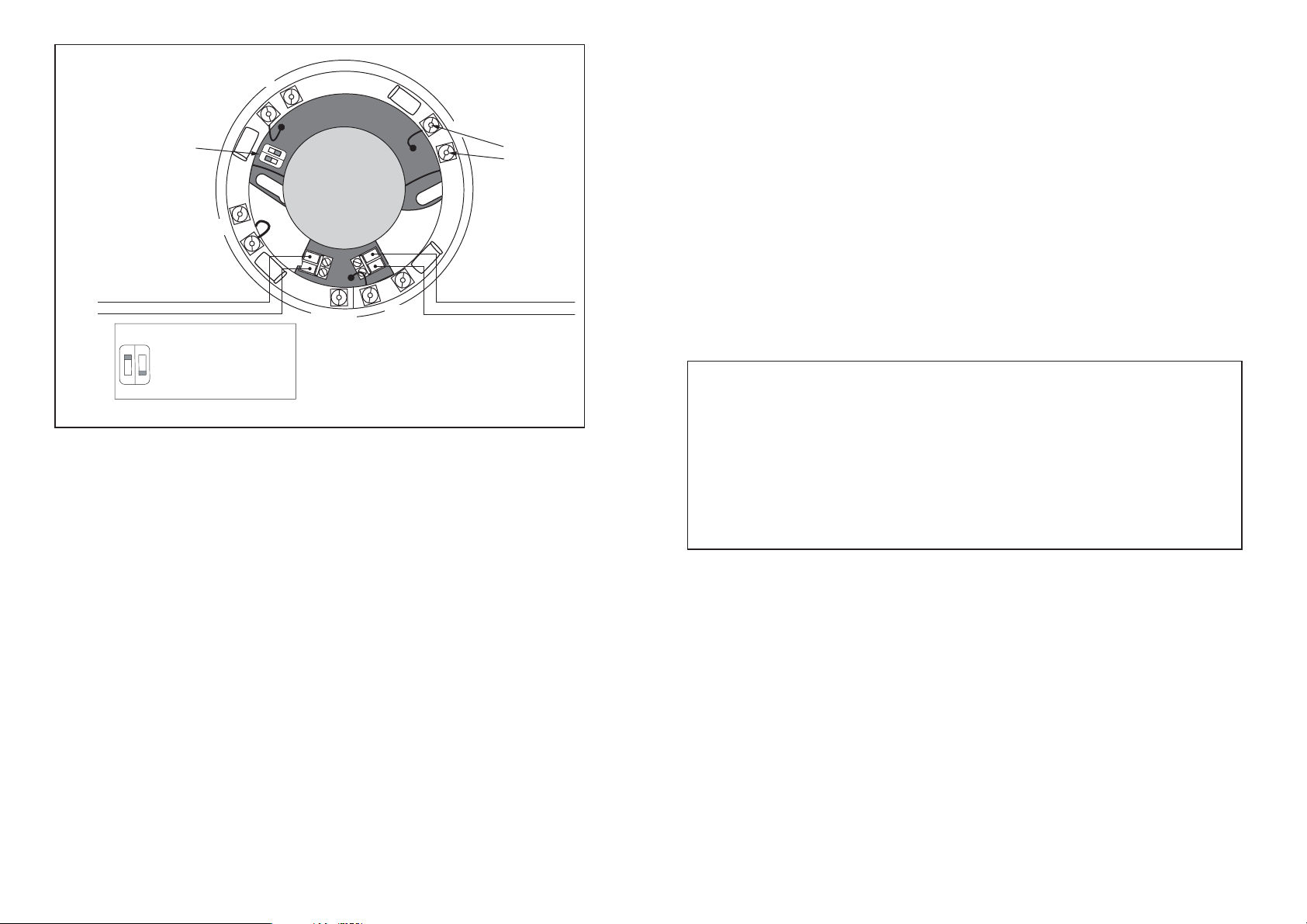
Fig 1 Sounder/Sounder Beacon Base
AlarmSense Sounder Beacon Base
The AlarmSense Sounder Beacon Base, part no 45681-509, combines a sounder with a
beacon and a detector base in one unit. The beacon is activated whenever the sounder is
active and cannot be controlled separately.
Note: the Sounder Beacon Base is factory set as a priority sounder.
Installation
1. Bring incoming and outgoing cable tails through the aper ture in the sounder. Screw the
sounder to a mounting box or directly to the mounting surface as required.
2. Connect the incoming two cables to +IN (L1) and –IN (L2) and outgoing cables to – OUT
(L2) and +OUT (L1).
3. The priority/non-priority feature and volume are set by means of the DIL switch, see Fig 1.
Note: This feature is not available on all AlarmSense control panels. Please check with control
panel manufacturer.
Apollo recommends that when a heat detector is attached to a sounder base/sounder
beacon base that the sounder is set as a ‘priority’ sounder.
For stand-alone sounders or sounder beacons, fi tted with either a white cap, part no. 45681-
294 or red cap, part no 45681-295
1. Follow the steps 1—3 above.
2. A wire link (not supplied) is required between L1 IN and L1 OUT to disable the head
removal signal.
3. When using the sounder base or sounder beacon base in stand-alone mode, the nonpriority feature is not available.
Technical Data: AlarmSense System
Operating Voltage
Detectors and MCP 9-33V
Sounders (off) 9-15V
Sounders (on) 18-33V
Sounder Output
High tone setting maximum volume 87dB(A)
Low tone setting volume nominally 70dB(A)
SPL polar plot data is available in document PP2203 available on request.
Troubleshoot ing
Before investigating individual units for faults, ensure the system wiring is fault free.
Fault Finding
Problem Possible Cause
Control panel reports zone fault EOL resistor not fi tted or incorrect value
Detector removed
Incorrect zone wiring
Incompatible control panel
Control panel reports alarm Incorrect EOL resistor
Detector or MCP in alarm state
Sounder fails to operate Incorrect wiring
Sounders disabled at control panel
Sounder operates continuously Incompatible control panel
MCP does not activate alarm Polarity reversed
MCP disabled at panel
2
7
 Loading...