

Page 1
36LF Series
Model PR-LF - Pressure Reducing Valve
SUBMITTAL SHEET
DESCRIPTION
Apollo® Model PR-LF (36LF Se ries) Pressure Re ducing Valves are designed to protect residential and commercial water distribution systems by controlling
excessive pressures. The valves are built for long reliable service with proven ASTM grade materials including a lead free* bronze body and stainless steel strainer.
LEAD FREE
Job Name:
Job Location:
Engineer:
Contractor:
Tag :
PO#:
Rep:
Wholesale Dist.:
FEATU R ES
• Lead Free* AB 1953 Certified
• Corrosion Resistant Bronze Body and Bonnet
• 100% Factory Tested, Preset to 50 psi (-01)
APPROVALS
• NSF/ANSI 372 Lead Free
• ASSE 1003
• CSA B356
• Control Pressure Ranges:
10-35 psi, 25-75 psi (Standard), 75-125 psi
• Integral SS Strainer
• Balanced Piston Design
• Internal Thermal Expansion Bypass
• Multiple Connection Options
• Optional Pressure Gauge or Tapping
• 100% Manufactured in USA
OPTIONS
• (P) - Tapped w/ Plug
• (G) - Tapped w/ Gauge
• (02) - 10-35 psig
• (03) - 75-125 psig
• (36) - with Standard Material for
Non-Potable Applications
PERFORMANCE RATING
• Maximum Supply Pressure up to 300 psig
• Temperature Range 33 °F – 180 °F
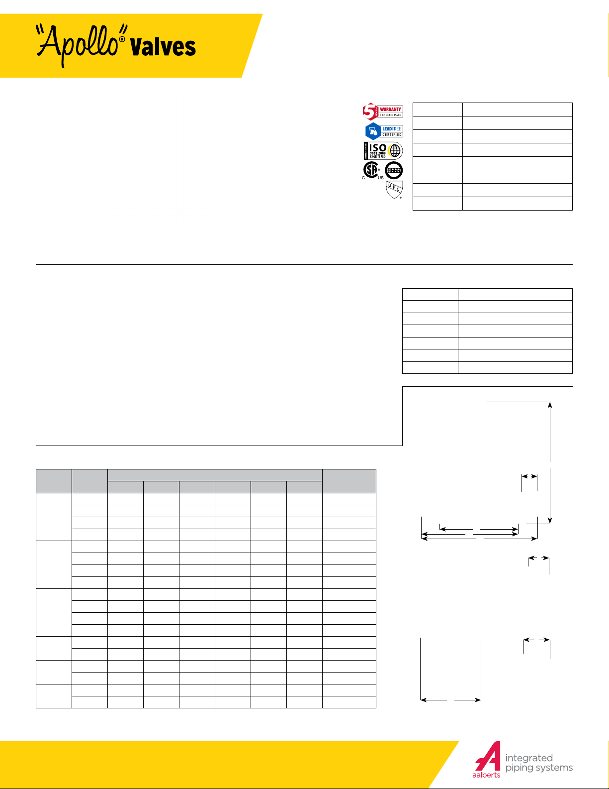
DIMENSIONS
SIZE
CONNECT
(IN.)
1/2”
3/4 ”
1- 1/4”
1-1/2”
2”
Nominal dimensions are shown. Allowances must be made for manufacturers’ tolerances.
TYPE
THREAD 4 4-7/8 5-5/8 5-7/8 5/8 2-3/4 3.5
SOLDER 4 4 -7/8 5-5/8 5-7/8 1/2 2-3 /4 3.4
PEX 4 5 5 -3/4 5-7/8 5/8 2 -3/4 3.3
CPVC 4 4-5/8 5 -1 /4 5-7/8 1/2 2-3/4 3.1
THREAD 3-7/8 4-7/8 5-5/8 5-7/8 5/8 2-3/4 3.4
SOLDER 3 -7/8 4-7/8 5-5/8 5 -7/8 3 /4 2-3 /4 3.3
PEX 3-7/8 5 5- 3/4 5-7/8 5/8 2-3/4 3.2
CPVC 3 -7/8 4-7/8 5-5/8 5 -7/8 5/8 2-3/4 3
THREAD 4-3/8 5-1/2 6-3/8 6-7/8 5/8 3-3/8 4.5
SOLDER 4-3/8 5-1/2 6 -3/8 6 -7/8 5/8 3-3/8 4.4
1”
PEX 4-3/8 5-1/2 6-5/8 6-7/8 7/8 3-3/8 4.3
CPVC 4-3/8 5 -3/4 7 6-7/ 8 3/4 3-3/8 4
THREAD 5-3/8 6-1/2 7-1/2 8 -7/8 7/8 4 10.2
SOLDER 5-3/8 6-5/8 7-3 /4 8 -7/8 1 4 10.1
THREAD 5-3/8 6-5/8 7-7/8 8 -7/8 3 /4 4 10.4
SOLDER 5-3/8 6 -3/4 8 8-7/8 1-1/8 4 10.3
THREAD 7-1 /8 8-1/2 9 -7/8 11-1/2 1 5-3/4 22.5
SOLDER 7-1/8 8 -7/8 10-1/2 11-1/2 1-3/8 5- 3/4 22.4
A B C D E F
DIMENSIONS (IN.)
WT. (U NIO N)
LB. EACH
STANDARD MATERIALS LIST
BODY
COVER
DIAP HR AGM
SEAT DISC
STEM
SPRING
O-RINGS
C89836 Lead Free* Bronze
Bronze, ASTM B5 84
FDA Grade Buna W/ Polyester
FDA Grade EPDM
C27450 Lead Free* Brass
Stainless Steel
NSF Gra de EPDM
A
B
C
F
E
E
PEX
E
Press
D
(704) 841-6000
apollovalves.com
SS1171 © 07/18 Page 1 of 2
This specification is provided for reference only. Apollo reserves the right to change any portion of this specification without
notice and without incurring obligation to make such changes to Apollo products previously or subsequently sold.
Most current information available at apollovalves.com.
Page 2
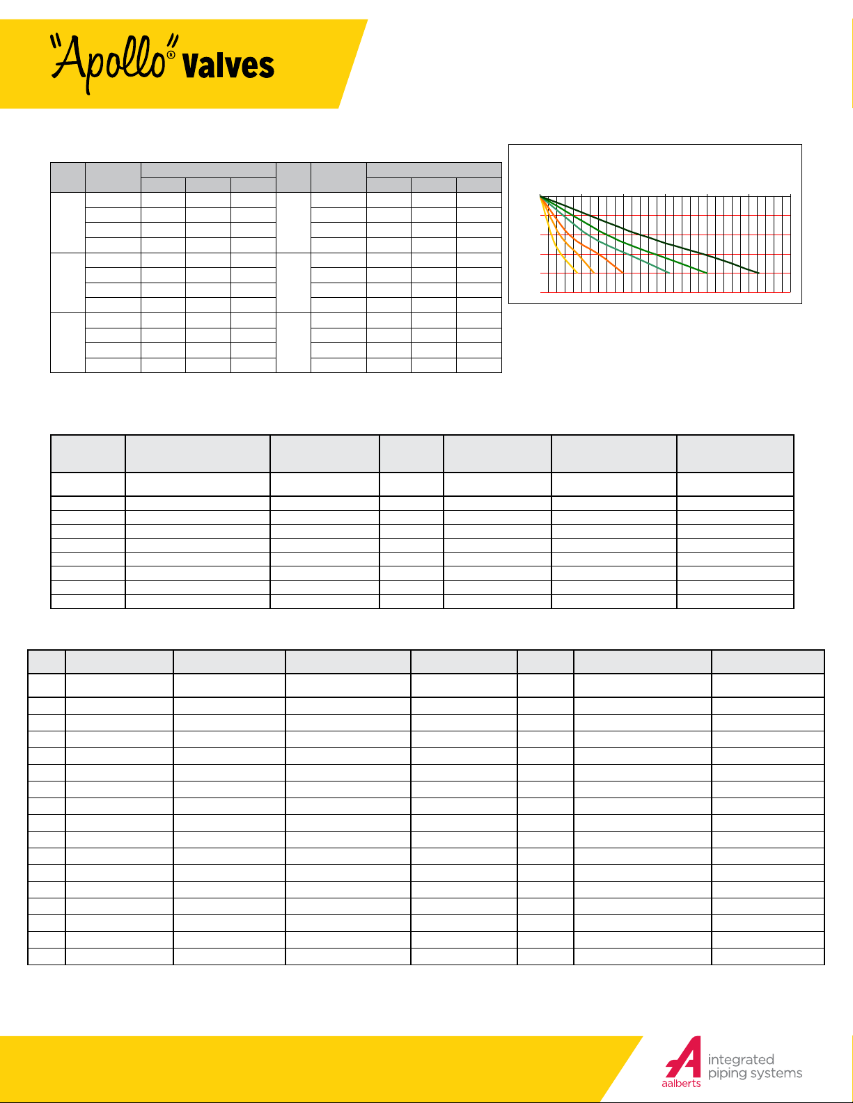
MODEL PR FLOW CHART
PRESSURE DROP (FALLOFF) psi
2"
1-1/2"
1-1/4"
1"
3/4"
1/2"
36 Series
Model PR - Pressure Reducing Valve
SUBMITTAL SHEET
FLOW CAPACIT Y
PIPE
FALL -OFF*
SIZE
1/2”
3/4 ”
1”
Note: Flow curves are based on static conditions of 100psi inlet pressure and 50 psi outlet pressure.
Pressure dierential is the dierence between the supply pressure and adjusted outlet pressure measured in the static (closed) condition.
Pressure fall-o is the decrease in downstream regulated pressure as the flow increases.
PRESSURE DIFFERENTIAL (PSI)
(PSI)
5 1.7 2 2.3
10 4.3 5 5.8 10 19.6 23 26.5
15 8.5 10 11.5 15 35.7 42 48.3
20 15.3 18 20.7 20 53 62 71
5 3.4 4 4.6
10 7.7 9 10.4 10 27 32 37
15 14.5 17 19.6 15 48 56 64
20 14.5 17 19.6 20 68 80 92
5 5.1 6 6.9
10 11.9 14 16.1 10 39 46 53
15 22.1 26 29.9 15 66 78 90
20 34 40 46 20 94 110 127
25 50 75 25 50 75
PIPE
SIZE
1- 1/4”
1-1/2”
2”
FALL -OFF*
PART NUMBER MATRIX
PRESSURE DIFFERENTIAL (PSI)
(PSI)
5 8.5 10 11.5
5 12 14 16
5 15 18 21
0 20 40 60 80 100 120
0
5
10
15
20
25
FLOW (GPM)
36LF
X X X X X X
36
SERIES CONNECTION OPTION SIZE GAUGE PRESSURE RANGE OPTION
36LF (LEAD FREE) 1 - SINGLE UNION NPT 0 - NO OPTION 3 - 1/2” 0 - NO GAUGE 1 - 25-75 PSIG PR - PRESS
36 2 - NO UNION NPT C - CPVC TAILPIECE 4 - 3/4” P - W/ GAUGE PORT 2 - 10-35 PSIG (APPLIES TO MODELS 36-20X
3 - SINGLE UNION SOLDER X NPT S - SEALED CAGE* 5 - 1” G - W/ GAUGE 3 - 75-125 PSIG AND 36LF20X ONLY)
4 - DOUBLE UNION NPT X - PEX F1807 TAILPIECE 6 - 1-1/4”
5 - DOUBLE UNION SOLDER 7 - 1-1/2”
6 - SINGLE UNION METER X NPT 8 - 2”
8 - DOUBLE UNION CPVC
* S option = Sealed cage with stainless steel adjusting screw for vault installation.
9 - DOUBLE UNION PEX F1807
MODEL NUMBER MATRIX
PR X X X X X X
UNION GAUGE PRESSURE RANGE MISC SIZE CONNECTION LEAD FREE
BLANK - SINGLE UNION BLANK - NO GAUGE BLANK - 25-75 PSIG BLANK - NO OPTION 12 - 1/2” BLANK - FNPT X FNPT LF - LEAD FREE
D - DOUBLE UNION P - W/ GAUGE PORT L - 10-35 PSIG A - SEALED CAGE 34 - 3/4” SINGLE UNION ONLY BLANK - NON-LEAD FREE
T - NO UNION G - W/ GAUGE H - 75-125 PSIG 1 - 1” BLANK - FNPT X FNPT
114 - 1-1/4” S - SOLDER X FNPT
112 - 1-1/2” C - CPVC X FNPT
2 - 2” X - PEX F1807 X FNPT
PR - PRESS X FNPT
DOUBLE UNION ONLY
S - SOLDER X SOLDER
C - PVC X CPVC
X - PEX F1807 X PEX F1807
B - BSPT X BSPT
SC - SOLDER X CPVC
SX - SOLDER X PEX F1807
CX - CPVC X PEX F1807
PR - PRESS X PRESS
(704) 841-6000
apollovalves.com
SS1171 © 07/18 Page 2 of 2
This specification is provided for reference only. Apollo reserves the right to change any portion of this specification without
notice and without incurring obligation to make such changes to Apollo products previously or subsequently sold.
Most current information available at apollovalves.com.
 Loading...