

Page 1

Document Number:
ES-1045-1
Revision Level:
H
Issued By:
T.HAMILTON
Date:
3/3/16
Approved By:
Date:
19 SERIES - SAFETY VALVE
INSTALLATION, OPERATION, & MAINTENANCE
Part I
Conbraco Industries, Inc.
P.O. Box 247
Matthews, NC 28106
(704) 841-6000
Fax (704) 841-6020
http://www.conbraco.com
Page 2
2
Table of Contents
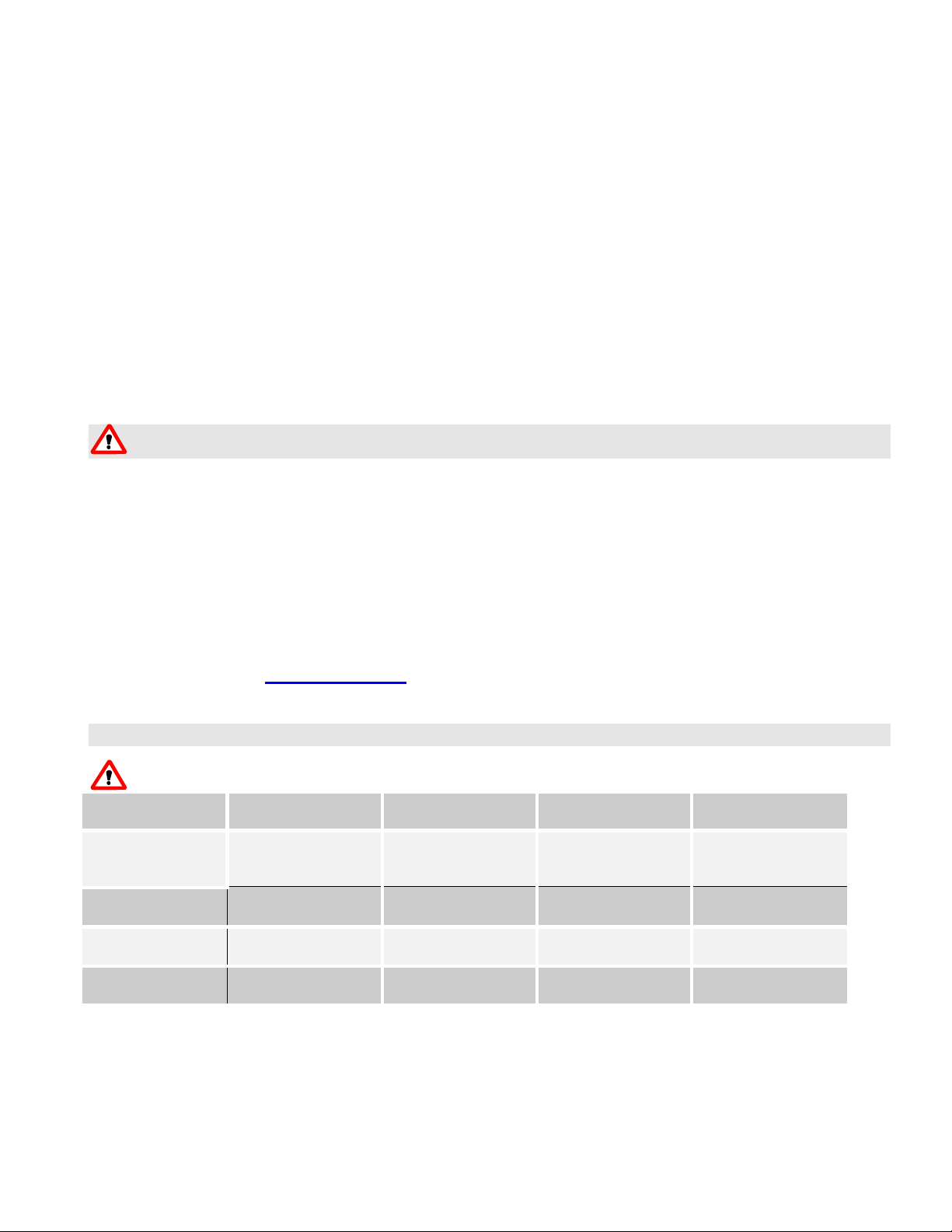
Series
19K
19M
19L
19S
Trim
Seat
Brass
PFA Teflon
®
Brass
Metal to Metal
Stainless Steel
PFA Teflon®
Stainless Steel
Metal to Metal
Max. Set – Steam
250 psi (1723.7 kPa)
250 psi (1723.7 kPa)
250 psi (1723.7 kPa)
300 psi (2068.4 kPa)
Max. Set – Air/Gas
300 psi (2068.4 kPa)
300 psi (2068.4 kPa)
300 psi (2068.4 kPa)
300 psi (2068.4 kPa)
Max. Temperature
406ºF (207.8ºC)
406ºF (207.8ºC)
406ºF (207.8ºC)
422ºF (216.7ºC)
Maximum Pressure/Temperature Chart ........................................................ 2
Installation Instructions ................................................................................... 3
Operating Instructions ..................................................................................... 3
Maintenance and Testing Instructions .......................................................... 4
19 Series Part Number Matrix ......................................................................... 4
Nameplate Information .................................................................................... 5
Amendment Register ....................................................................................... 6
IMPORTANT
Conbraco pressure relief valves are safety devices designed for the protection of lives and property. These
valves will provide years of service when properly installed and maintained. The information contained herein is
intended for use by qualified personnel to properly maintain these devices.
Serious property damage and injury or death may occur should a pressure relieving device fail to operate
correctly. Any installation, maintenance, adjustment, repair or testing should only be performed by experienced
personnel properly trained and qualified in accordance with applicable codes and standards.
When maintaining or repairing Conbraco pressure relief valves, use only original Conbraco parts to ensure safe
and reliable operation.
Contact your local Conbraco factory representative for the name of a factory authorized repair center near you.
Or visit us on the web at www.conbraco.com.
Maximum Pressure/Temperature Chart
Warning – Application must not exceed the pressure/temperature limitations below.
ES1045-1, IOM, 19 Series Rev. H
Page 3

3
Installation Instructions
This quality Conbraco safety valve, along with proper installation, use and maintenance will provide many years
of reliable service and protection against excessive pressure build-up of steam, air or non-hazardous gas. Use of
this valve for any other purpose or media places all responsibility upon the user. Before installing valve, or
operating equipment to which it is installed, read all instructions carefully.
Caution - Always wear proper safety equipment.
Caution – Valve may be very hot to the touch. Wear protective equipment if necessary.
1. Installation must be performed by qualified service personnel only.
2. It is the piping system designer’s responsibility to implement appropriate protective measures to minimize reaction
forces and moments which result from supports, attachments, piping, etc.
3. Service is to be compatible with the materials of construction. Prior to selection it is the user’s responsibility to
determine that the valve is appropriate for the intended application. Application not to allow corrosion >.001”/year (.025
mm/year).
4. The capacity rating of this valve must equal or exceed that of the equipment to which it is installed.
5. Do not use this valve on a coal or wood fired boiler having an uncontrolled heat input.
6. Do not use the test lever as a lifting device during installation.
7. Insure that all connections, including the valve inlet, are clean and free of any foreign material.
8. Use pipe compound sparingly or tape on external threads only.
9. Do not use a pipe wrench! Use proper type and size wrench on wrench pads only.
10. This valve must be mounted in a vertical upright position directly to a clean tapped opening in the top of the pressure
vessel. Under no circumstances should there be a flow restriction or valve of any type between the safety valve and
pressure vessel.
11. Do not plug or obstruct valve body drain. A body drain line should be installed to dispose of condensate.
12. See ASME Boiler and Pressure Vessel Code and local jurisdiction for additional installation and operating instructions.
Caution - During operation, this valve may discharge large amounts of high pressure steam, hot water, air or
gas. To reduce the potential for bodily injury and property damage, a discharge line must be installed that:
a) is connected from the valve outlet to a safe point of discharge with no intervening valve;
b) allows complete drainage of the valve and discharge line;
c) is independently supported and securely anchored to avoid applied stress on the valve;
d) is as short and straight as possible;
e) terminates freely to atmosphere where any discharge will be clearly visible and is at no risk of freezing;
f) is, over it’s entire length, of a pipe size equal to or greater than the valve outlet. Use only schedule 40 pipe for
discharge. Do not use schedule 80, extra strong or double strong pipe or connections. Do not cap, plug or obstruct
discharge pipe outlet! If discharge is piped upward, a condensate drain must be provided in the elbow below the
vertical pipe to prevent condensate from returning into the valve. A Conbraco Drip Pan Elbow is ideal.
Operating Instructions
If adding water to a boiler, do not allow water to flow through safety valve as sediment or debris may be deposited on seating surfaces.
To achieve topmost performance and maximum service life, it is necessary to maintain a proper pressure margin between
the set pressure of the safety valve and the operating pressure of the equipment. The minimum recommended operating
pressure margin for this type of safety valve is 5 psi for pressures up to 70 psig and is 10% of set pressure for pressures
above 70 psig. Failure to maintain this operating margin may result in leakage past the seat and an accumulation of
deposits on the seating surface. Excessive deposits may prevent the safety valve from operating properly, and a
dangerous pressure build-up and equipment rupture may result.
ES1045-1, IOM, 19 Series Rev. H
Page 4

4
Maintenance and Testing Instructions
CAUTION! Before testing, make certain discharge pipe is properly connected to valve outlet and arranged to
contain and safely dispose of discharge (see Installation Instructions).
Under normal operating conditions a “try lever test” should be performed biannually in steam service, with a visual
inspection every 2 months and an annual pressure test. In air/gas service, perform a visual inspection every 6 months, a
lever test annually and a pressure test every 3 years. Under severe service conditions or if corrosion, pitting, and/or
deposits are noticed within the valve body, testing must be performed more often. A “try lever test” should be performed at
the end of any non-service period.
CAUTION! Hot, high pressure fluid may be discharged from body drain during lever test.
CAUTION! High sound levels may be experienced during lever test. Wear proper safety equipment and
exercise extreme care.
Test at or near maximum operating pressure by holding the test lever fully open for at least five seconds to flush the valve
seat free of sediment and debris. Then release lever and permit valve to snap shut. If lift lever does not actuate, or there is
no evidence of discharge, turn off equipment immediately and contact a licensed contractor or qualified service personnel.
For resetting, adjustment or repairs contact Conbraco Industries for the appropriate service facility.
Neither Conbraco Industries, Inc. nor it’s agents assume any liability for valves improperly installed or maintained.
19 Series Part Number Matrix
EX: 19KDCA50
POSITION OPTION
1-2: SERIES # 19 = 19 SERIES
3: TRIM E = BRASS TRIM W/EPR O-RING SEAT (100 PSI MAX)
K = BRASS TRIM W/PFA SOFT SEAT
M = BRASS TRIM W/METAL SEAT
L = STAINLESS STEEL TRIM W/PFA SOFT SEAT
S = STAINLESS STEEL TRIM W/METAL SEAT
4: ORIFICE SPECIFY D/E/F/G/H/J
5: INLET C = ½ NPT
D = ¾ NPT
E = 1 NPT
F = 1-1/4 NPT
G = 1-1/2 NPT (1-1/2 FNPT, J ORIFICE ONLY)
H = 2 NPT
J = 2-1/2NPT
6: SERVICE A = ASME SECTION I (V) STEAM
K = ASME SECTION VIII (UV) AIR/GAS
L = ASME SECTION VIII (UV) STEAM
N = NON-CODE AIR/GAS
P = NON-CODE STEAM
7+: SET PRESSURE 5 THRU 300, PSIG
DIGITS AFTER SET PRESSURE INDICATE ADDITIONAL FEATURES; A = ANTI-VIBRATION
FACTORY ISSUED LETTERS/NUMBERS FOR SPECIAL OPTIONS. X = OXYGEN CLEAN
ES1045-1, IOM, 19 Series Rev. H
Page 5

5
Nameplate Information
SET
SIZE
DNIN
PSIG
BARG
MODEL
0035
Valves
CON BRACO INDUS TRIES INC., U SA
DT
N
E
M
S
A
CRN 0G8547.5C
ISO 4126- 1
CAP
LB/HR SCFM GPM
19MFEL125
1
25
8.6
125
2325 x 0412
A=233mm2 S-.826 LIFT 4.3mm @ 10%
UV
ASME Code Symbol
When applicable, the ASME “V” or “UV” stamp will be added in the empty box in the upper right corner. The “V” symbol signifies the
valve has been designed, manufactured, and tested in accordance with Section I of the ASME Boiler and Pressure Vessel Code and is
approved for use on power boilers. The “UV” symbol signifies the valve has been designed, manufactured, and tested in accordance
with Section VIII of the ASME Boiler and Pressure Vessel Code and is approved for use on unfired pressure vessels and pressure
piping systems.
NB Symbol
This symbol indicates the capacity value stamped on the nameplate has been certified by the National Board of Boiler and Pressure
Vessel Inspectors.
CRN
The design registration number in accordance with CSA B51, the Canadian Boiler, Pressure Vessel and Pressure Piping Code.
MODEL
The valve model number as described in the Part Number Matrix.
CAP
The approved capacity of the valve. One of the three adjacent boxes will be marked to indicate the units of the capacity rating.
SET
The set pressure of the valve in pounds per square inch and bar gauge.
SIZE
The inlet size of the valve in inches.
A
The orifice area in square millimeters.
TS
The maximum allowable temperature.
S
The derated coefficient of discharge indicating reference fluid: ‘G’ for gas, ‘S’ for steam, and ‘L’ for liquid.
DN
The metric size designation of the inlet.
DATE
The date of manufacture. The first two numbers indicate the year (04=2004), and the last two numbers indicate the week of the year
(12=12th week of the year).
LIFT
The minimum lift at specified overpressure.
ES1045-1, IOM, 19 Series Rev. H
Page 6

6
Amendment Register
DATE
REV
PAGES
DESCRIPTION
11/9/00
A
ALL
NEW RELEASE
2/20/01
B
ALL
CHANGED DOCUMENT No.
7/18/01
C
14-16
Updated Capacities
3/04/02
D
9-10
Removed Pack Lever/Screw Cap
8/22/02
E
ALL
Split into two sections
4/29/04
F 5 UPDATED NAMEPLATE GRAPHICS
9/19/05
G 4 ADDED MODEL 19E
3/3/16
H 5 UPDATED NAMEPLATE
ES1045-1, IOM, 19 Series Rev. H
 Loading...