


BRONZE SWING CHECK VALVE
INSTALLATION
OPERATION
MAINTENANCE
GUIDE
61Y & 61YLF SERIES
MODELS:
161S/161SLF
161T/161TLF
162T/162LF
163T/163TLF
163S/163SLF
164T
168T
169T
APOLLO® BRONZE SWING CHECK VALVE IOM GUIDE Page 2 of 4
2
SERIES
MODEL
DESCRIPTION
61Y-09x-01
161S
Class 125 Bronze Disc, Solder end connection, Y-pattern
61Y-19x-01
161T
Class 125 Bronze Disc, NPT end connection, Y-pattern
61Y-20x-V1
162T
Class 125 Viton Disc, NPT end connection, Y-pattern
61Y-20x-T1
163T
Class 125 PTFE Disc, NPT end connection, Y-pattern
61Y-10x-T1
163S
Class 125 PTFE Disc, Solder end connection, Y-pattern
61Y-21x-01
164T
Class 150 Bronze Disc, NPT end connection, Y-pattern
61Y-75x-01
168T
Class 300 Bronze Disc, NPT end connection, Y-pattern
61Y-75x-T1
169T
Class 300 PTFE Disc, NPT end connection, Y-pattern
61YLF-09x-01
161S-LF
Class 125 Lead Free Bronze Disc, Solder end connection, Y-pattern
61YLF-19x-01
161T-LF
Class 125 Lead Free Bronze Body & Disc, NPT end connection, Y-pattern
61YLF-20x-V1
162T-LF
Class 125 Lead Free Bronze Body, Viton Disc, NPT end connection, Y-pattern
61YLF-20x-T1
163T-LF
Class 125 Lead Free Bronze Body, PTFE Disc, NPT end connection, Y-pattern
61YLF-10x-T1
163S-LF
Class 125 Lead Free Bronze Body,PTFE Disc, Solder end connection, Y-pattern
Class 125
Saturated Steam
125 psi (8.6 Bar) to 353°F (178°C)
Cold Water
200 psi (13.8 Bar) at 100°F
Class 150
Saturated Steam
150 psi (10.3 Bar) to 366°F (185°C)
Cold Water
300psi (20.7 Bar) at 100°F
Class 300
Saturated Steam
300 psi (20.7 Bar) to 423°F (217°C)
Cold Water
1000psi (68.9 Bar) at 100°F
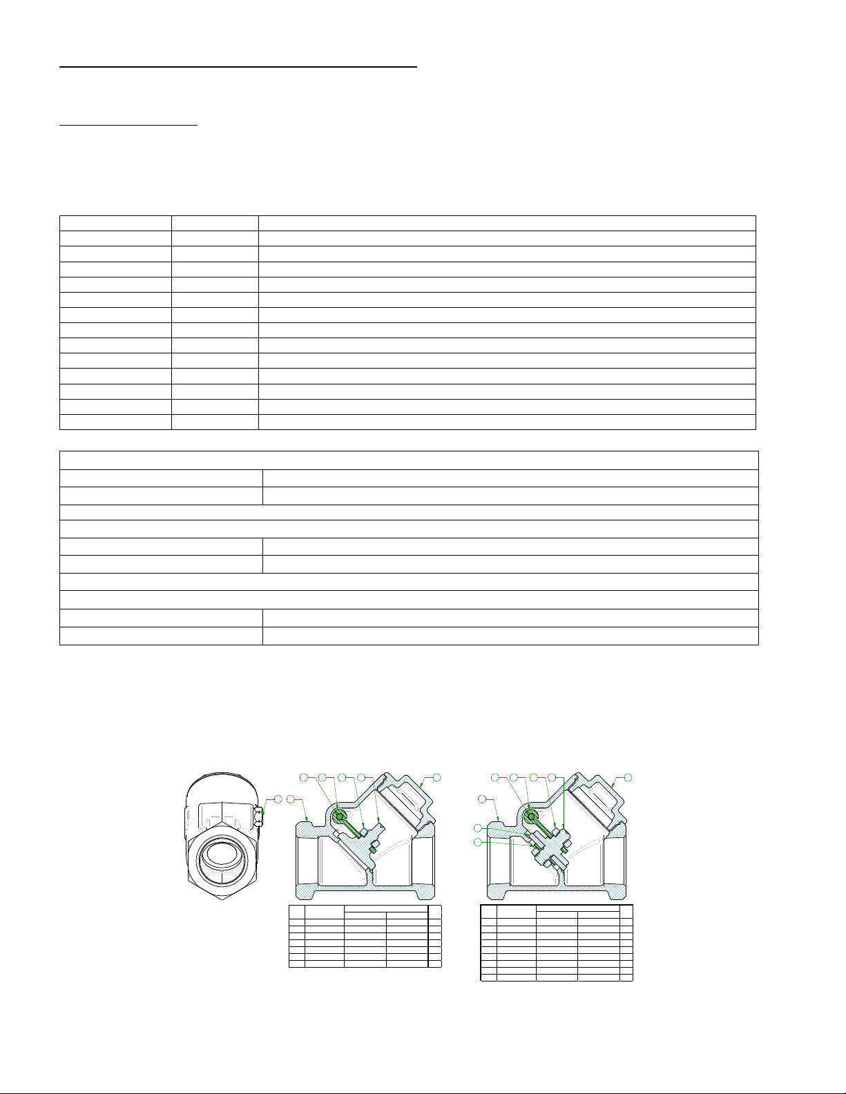
Class 125 & 150 Class 300
1 PLUG ASTM B16 ASTM B16 1
2 CAP ASTM B62 ASTM B61 1
3 DISC ASTM B62 ASTM B61 1
4 HANGER 304 SS 304 SS 1
5 PIN, HANGER 304 SS 304 SS 1
6 NUT ASTM B16 ASTM B16 1
7 BODY ASTM B62 ASTM B61 1
MATERIAL
ITEM
DESCRIPTION
QTY
Class 125 & 150 Class 300
1 PLUG ASTM B16 ASTM B16 1
2 CAP ASTM B62 ASTM B61 1
3 DISC ASTM B62 ASTM B61 1
4 HANGER 304 SS 304 SS 1
5 PIN, HANGER 304 SS 304 SS 1
6 NUT ASTM B16 ASTM B16 2
7 BODY ASTM B62 ASTM B61 1
8 SEAT PTFE PTFE 1
9 WASHER ASTM B16 ASTM B16 1
MATERIAL
ITEM
DESCRIPTION
QTY
1
234 65
7
234 65
7
8
9
Type 3 Swing Check Valve Type 4 Swing Check Valve
INTRODUCTION
The Apollo Bronze Swing Check valves covered in these guidelines are Class 125, Class 150 & Class 300
bronze, metal seat and soft seat valve types. Check Valves are used in piping systems where flow in one
direction is desired. Arrow on side of valve indicates flow direction. If backflow occurs in the system the
swing check disc will close onto sealing surface of body not allowing the flow to reverse.
Table 2 Pressure Ratings
These ratings are the maximum allowable, non-shock pressures at the temperatures shown and
allowable pressures may be interpolated between temperatures shown. Use of a pressure rating at a
material temperature other than the temperature of the contained fluid is the responsibility of the user,
and subject to the requirements of applicable codes. The safe pressure-temperature rating of a solder
joint valve is dependent on the composition of the solder used. All valves are 100% pneumatically shell
and seat tested at a pressure of 80 psi in accordance with MSS-SP-80 Manufacturers Standardization
Society requirements.
Swing Check 61Y ES 1498 a.pdf.doc 1418 S. Pearl Street Pageland SC USA 29728

APOLLO® BRONZE SWING CHECK VALVE IOM GUIDE Page 3 of 4
3
INSTALLATION
Inspection
Threads of mating pipe must be clean and machined to appropriate ANSI/ASME specifications.
Ends of mating copper tubing or pipe must be square and free of burrs. Use emery cloth to clean and
remove grease and/or oxidation before soldering. Inspect sealing surfaces of valve for cleanliness prior to
installing.
Mounting
Swing check valves can be mounted in either vertical or horizontal position with upward flow or in any
intermediate position. Flow must be by direction of arrow in body.
It is not recommended that swing check valve be mounted in close proximity to reciprocating pumps or
compressors due constant pressure fluctuations which shortens the life of the valve.
NPT connection
It is recommended that the valve is mounted in the closed position. Gently thread valve to mating pipe
by hand until resistance is felt. Using a wrench tighten the valve using the hex flats at the joint being
tightened. Do not tighten through the valve body using hex flats on opposite end of joint being
tightened.
Solder connection
It is recommended that the valve be in the open position. Care must be taken to apply the proper
amount of solder so that it does not flow into valve seat area. During soldering, the mid-portion of the
valve body should not exceed 300°F. This can be monitored using Tempilstik® or an infra-red
temperature sensor. Depending on the fuel selected and the orientation of the installation it may be
necessary to wrap the valve body with wet rags or employ other heat absorbing techniques. The flame
must be directed away from the valve body, concentrated on the solder cup. The cup should be heated
evenly. Once one of the joints is complete, the valve should be allowed to cool until "cool to the touch"
before beginning the second joint.
Fuel Flame temp w/Oxygen
Propane 5122°F (2828°C)
Propylene 5245°F (2896°C)
MAPP Gas 5389°F (2976°C)
Acetylene 5720°F (3160°C)
WARNING: Excessive heat input will damage the body seal resulting in leaks at the valve body joint.
Press connection
Valve can be in either closed or open position. Piping must be properly supported so that valve fits
squarely before pressing. Do not solder any joint within 12” of press connection.
Compatible piping: Copper water tube per ASTM B88, Types K, L, & M.
(Not for use with steam service)
Push connection
Valve can be in either closed or open position.
Compatible piping: Copper water tube per ASTM B88, Types K, L, & M, both hard drawn
(Not for use with steam service)
OPERATION
Swing check valve functions by allowing flow forces to move the disc from the closed position to the fully
open position in a sweeping arc motion against a hinge-stop inside the valve body. Due to the weight and
center-of-gravity location of the disc and swing arm assembly, the valve will return to the closed position
should flow become interrupted or reversed.
Swing check valve produces the lowest pressure drop when compared with other check valves of the
same size. They feature a simple design that is easy to maintain. Swing check valves with metal seated
Swing Check 61Y ES 1498 a.pdf.doc 1418 S. Pearl Street Pageland SC USA 29728

APOLLO® BRONZE SWING CHECK VALVE IOM GUIDE Page 4 of 4
4
disc have a maximum permissible leakage rate per MSS SP-80 of 40ml of water per hour per inch of pipe
size. Soft-seated/resilient disc have bubble-tight seal during reverse flow.
MAINTENANCE
If the cap/hinge leaks, isolate and depressurize the unit. Check for damage or wear. If damage is due to
scratches or nicks, repair damage area by resurfacing to maintain flatness and seal using a thread
sealant.
Seat leakage can be resolved by:
Flushing seat area with high rate of flow through the valve. In some cases, foreign materials or debris
causes the disc to completely close allowing leak across the check. If seat leakage persists, dismantle
valve and verify cause.
Scratches or dents on seat and disc can be corrected by lapping disc while it is in the body. Apply
lapping compound on the disc and seat, and apply mild amount of pressure to lap both surfaces.
If lapping cannot resolve seat leakage, replace disc.
In Viton or PTFE disc, it is recommended to replace it.
Swing Check 61Y ES 1498 a.pdf.doc 1418 S. Pearl Street Pageland SC USA 29728
 Loading...