

Page 1

BRONZE GATE VALVE
INSTALLATION
OPERATION
MAINTENANCE
GUIDE
30 & 30LF SERIES
MODELS:
101T/101TLF
102T/102TLF
102S/102SLF
103T/103TLF
106T
107T
111T
116T
102TK
DOCUMENT NO.: ES-1496
REVISION LEVEL: B
ISSUED BY: Bill Hooks DATE: 08/7/13
APPROVED BY: _________________ DATE: _______
Page 2
APOLLO® BRONZE GATE VALVE IOM GUIDE
Page 2 of
4
INTRODUCTION
The Apollo Bronze Gate valves covered in these guidelines are bronze, threaded and union
bonnet; rising stem and non rising stem valve types. They are used to start or stop the flow of
fluid in a piping system. The valves are operated from a handwheel. These valves should be
used in the full open or full closed position only. Flow through the valve is stopped by forcing a
wedge (disc) down between the tapered body seats.
Table 1 Apollo Series & Model Numbers
SERIES MODEL DESCRIPTION
30-00x-01 101T Class 125 Rising stem, Threaded bonnet, NPT connection
30-03x-01 102T Class 125 Non rising stem, Threaded bonnet, NPT connection
30-04x-01 102S Class 125 Non rising stem, Threaded bonnet, Solder connection
30-05x-01 103T Class 125 Rising stem, Union bonnet, NPT connection
30-20x-01 107T Class 150 Rising stem, Union bonnet, NPT connection
30-28x-01 106T Class 150 Non rising stem, Threaded bonnet, NPT connection
30-44x-01 111T Class 300 Rising stem, Union bonnet, Integral seat, NPT connection
30-45x-01 116T Class 300 Rising stem, Union bonnet, Stainless steel seat, NPT connection
30-03x-01K 102T-K Class 125 Non rising stem, Threaded bonnet, NPT connection, Irrigation
x – indicates pipe size.
Table 2 Lead Free Apollo Series & Model Numbers
SERIES MODEL DESCRIPTION
30LF-00x 101TLF Class 125 Rising stem, Threaded bonnet, NPT, Lead Free
30LF-03x 102TLF Class 125 Non rising stem, Threaded bonnet, NPT, Lead Free
30LF-04x 102SLF Class 125 Non rising stem, Threaded bonnet, Solder, Lead Free
30LF-05x 103TLF Class 125 Rising stem, Union bonnet, NPT, Lead Free
x – indicates pipe size.
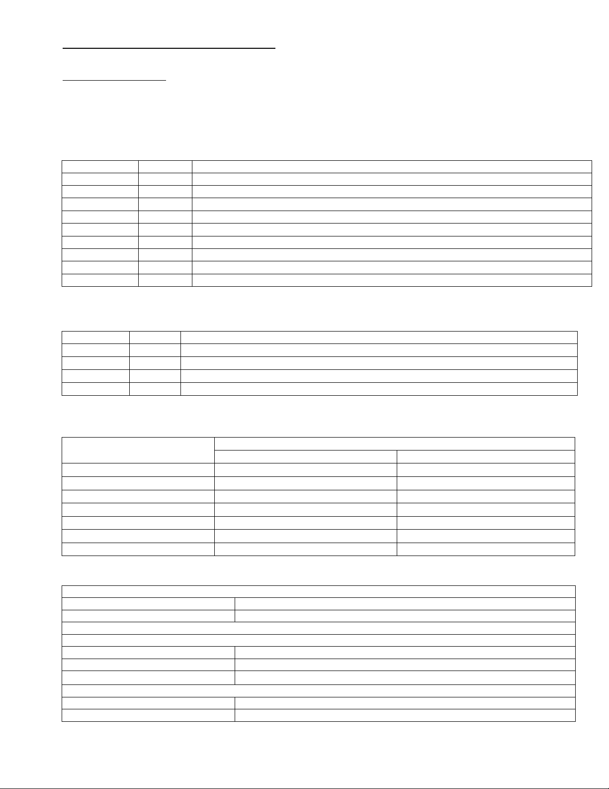
Table 3 Material Specifications
Part Name
Body ASTM B62 Bronze ASTM B61 Bronze
Bonnet ASTM B62 Bronze ASTM B61 Bronze
Stem ASTM B371 Bronze ASTM B371 Bronze
Disc ASTM B62 Bronze ASTM B61 Bronze
Packing Grafoil® Grafoil®
Hand Wheel Malleable Iron Malleable Iron
Nameplate Aluminum Aluminum
Table 4 Pressure Ratings
Class 125
Saturated Steam 125 psi (8.6 Bar) to 353°F (178°C)
Cold Water 200 psi (13.8 Bar) at 100°F
Class 150
Saturated Steam 150 psi (10.3 Bar) to 366°F (185°C)
Cold Water 300psi (20.7 Bar) at 100°F
Class 125/150 Class 300
Material
Class 300
Saturated Steam 300 psi (20.7 Bar) to 423°F (217°C)
Cold Water 1000 psi (68.9 Bar) at 100°F
ES1496 Rev B IOM Bronze Gate Valve 1418 S. Pearl Street Pageland SC USA 29728
Page 3

APOLLO® BRONZE GATE VALVE IOM GUIDE
Page 3 of
4
These ratings are the maximum allowable, non-shock pressures at the temperatures shown
and allowable pressures may be interpolated between temperatures shown. Use of a pressure
rating at a material temperature other than the temperature of the contained fluid is the
responsibility of the user, and subject to the requirements of applicable codes.
The safe pressure-temperature rating of a solder joint valve is dependent on the composition of
the solder used.
All valves are 100% pneumatically shell and seat tested at a pressure of 80 psi in accordance
with MSS-SP-80 Manufacturers Standardization Society requirements.
INSTALLATION
Inspection
Threads of mating pipe must be clean and machined to appropriate ANSI/ASME specifications.
Ends of mating copper tubing or pipe must be square and free of burrs. Use emery cloth to
clean and remove grease and/or oxidation before soldering. Inspect sealing surfaces of valve for
cleanliness prior to installing.
Mounting
Gate valves are bi-directional and can be installed for flow in either direction. Gate valves can
be mounted in either stem vertical upward or horizontal position. Vertical mounting position is
recommended as horizontal positioning will not allow valve to fully drain leading to
contamination.
NPT connection
It is recommended that the valve is mounted in the closed position. Gently thread valve to
mating pipe by hand until resistance is felt. Using a wrench tighten the valve using the hex
flats at the joint being tightened. Do not tighten through the valve body using hex flats on
opposite end of joint being tightened.
Solder connection
It is recommended that the valve be in the open position. Care must be taken to apply the
proper amount of solder so that it does not flow into valve seat area. During soldering, the midportion of the valve body should not exceed 300°F. This can be monitored using Tempilstik® or
an infra-red temperature sensor. Depending on the fuel selected and the orientation of the
installation it may be necessary to wrap the valve body with wet rags or employ other heat
absorbing techniques. The flame must be directed away from the valve body, concentrated on
the solder cup. The cup should be heated evenly. Once one of the joints is complete, the valve
should be allowed to cool until "cool to the touch" before beginning the second joint.
Fuel Flame temp w/Oxygen
Propane 5122°F (2828°C)
Propylene 5245°F (2896°C)
MAPP Gas 5389°F (2976°C)
Acetylene 5720°F (3160°C)
WARNING: Excessive heat input will damage the body seal resulting in leaks at the valve
body joint. In extreme cases, seats and stem packing may also be damaged.
Press connection
Valve can be in either closed or open position. Piping must be properly supported so that valve
fits squarely before pressing. Do not solder any joint within 12” of press connection.
Compatible piping: Copper water tube per ASTM B88, Types K, L, & M.
(Not for use with steam service)
Push connection
Valve can be in either closed or open position.
Compatible piping: Copper water tube per ASTM B88, Types K, L, & M, both hard drawn
(Not for use with steam service)
ES1496 Rev B IOM Bronze Gate Valve 1418 S. Pearl Street Pageland SC USA 29728
Page 4

APOLLO® BRONZE GATE VALVE IOM GUIDE
Page 4 of
4
OPERATION
Gate valves are intended to provide years of reliable service in an on/off application. They are
used to restrict flow when needed. Gate valves are not to be used for throttling as seat damage
may result. They should always be operated in a fully open or fully closed position. Gate valves
have a permissible leakage rate per MSS SP-80 of 10ml per hour per inch of pipe size.
MAINTENANCE
Valves must be actuated frequently depending on fluid corrosiveness to assure contamination
or deposits do not collect causing seizure and seat leak.
Seat leakage can be resolved by:
□ Flushing seat area with high rate of flow through the valve.
□ Additional torque using hand wheel maybe needed.
□ Disassembly and cleaning of seat area. Minor scratches can be corrected by evenly
polishing the disc face using 400 grit sand paper. If body sealing surfaces are damaged it is
recommended replacing valve due to difficulty of correcting damaged area.
□ Replacement of disc.
Bonnet/Body joint leakage can be resolved by:
□ Union Bonnet Gate Valves
.1 Remove bonnet after valve has been depressurized.
.2 Inspect body and bonnet sealing area for minor scratches and defects.
.3 Minor scratches and defects on body sealing surface can be corrected by sanding on a flat
plate using 400 grit sandpaper.
.4 Once imperfections have been corrected reassemble bonnet to body.
□ Threaded Bonnet Gate Valves
.1 Remove bonnet after valve has been depressurized.
.2 Add Loctite 246 to threaded portion of bonnet and reassemble.
Stem/Bonnet leakage can be resolved by:
□ Tighten packing gland nut. Hand wheel torque is affected by the tightness of this packing,
so care must be taking to not over-tighten.
If there is no travel left on the packing gland, packing should be replaced. Backseat feature
can be used to reduce leakage until system can be isolated and depressurized for packing
replacement.
CAUTION: Packing should not be replaced while valve is under pressure. This could lead to
serious injury.
ES1496 Rev B IOM Bronze Gate Valve 1418 S. Pearl Street Pageland SC USA 29728
 Loading...