

Page 1

INSTALLATION, OPERATION & MAINTENANCE MANUAL
1/2” - 2” Pressure Vacuum Breaker (PVB) Backflow Preventer
PVB4A
ES1599 IOM BFMMPVB4A rev.a
Page 2
INSTALLATION, OPERATION &
MAINTENANCE MANUAL
SECTION DESCRIPTION PAGE
I Description and Operation 3
II Installation 3
III Troubleshooting Guide 5
IV Maintenance Instructions 5
V Testing Procedures 6-7
Parts List
Parts List (1/2”- 2”) 8-10
Repair Kits
Repair Kits (1/2”- 2” ) 11
2
Customer Service (704) 841-6000
backflow.apollovalves.com
Page 3

BFMMPVB4A
ES1599 REV A
I. DESCRIPTION AND OPERATION
The Apollo® PVB4A Series Pressure Type Vacuum Breaker consists of a replaceable check valve cartridge and a unique atmospheric vent bonnet/float
assembly located between two resilient seated shut-o valves. The modular design allows for unprecedented ease of inspection and maintenance.
During normal flow conditions, the check valve remains open and the float seals on the bonnet assembly. A minimum supply pressure of 10 psig is
normally required to fully shut the float. As the line pressure falls to 1 psig, a spring-loaded atmospheric vent valve opens, breaking the vacuum and
thereby preventing back-siphonage. In the event of exposure to short-term freezing temperatures, a spring-loaded relief valve in the float protects the
PVB body and internal components from damage. As the temperature increases above freezing, the relief valve automatically reseats. During normal
operating conditions, the relief valve will not discharge.
NOTE: The freeze resistant feature is for a short term dip in temperature. The PVB should be winterized for extended periods below freezing.
II. INSTALLATION
Pressure vacuum breaker assembly’s critical level (CL is marked in raised lettering on the body of the PVB) should be installed at least 12 inches above
the highest piping or outlet downstream of the device and with the supply line connected to the bottom of the device. Install the device in an accessible
location to facilitate periodic field-testing and any required maintenance. Contact local water authorities for installation/service requirements.
Flush upstream piping thoroughly to remove foreign matter prior to installation. Use pipe dope sparingly on external threads only. When initially
pressurizing the device, some spillage of water from the air inlet may occur.
To winterize the valve:
1. Secure the water source at a location that will not freeze.
2. Open #1 and #2 test cocks to drain the PVB.
3. Place the inlet and outlet isolation ball valves in the halfway open/shut position.
4. If possible, blow the lines clear with pressurized air.
Customer Service (704) 841-6000
backflow.apollovalves.com
3
Page 4
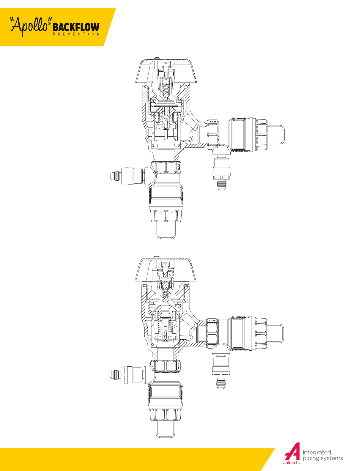
FIGURE 1
(FLOWING CONDITION)
INSTALLATION, OPERATION &
MAINTENANCE MANUAL
FIGURE 2
(NO FLOW
CONDITION)
4
Customer Service (704) 841-6000
backflow.apollovalves.com
Page 5
III. TROUBLESHOOTING
SYMPTOM CAUSE CORRECTIVE ACTION
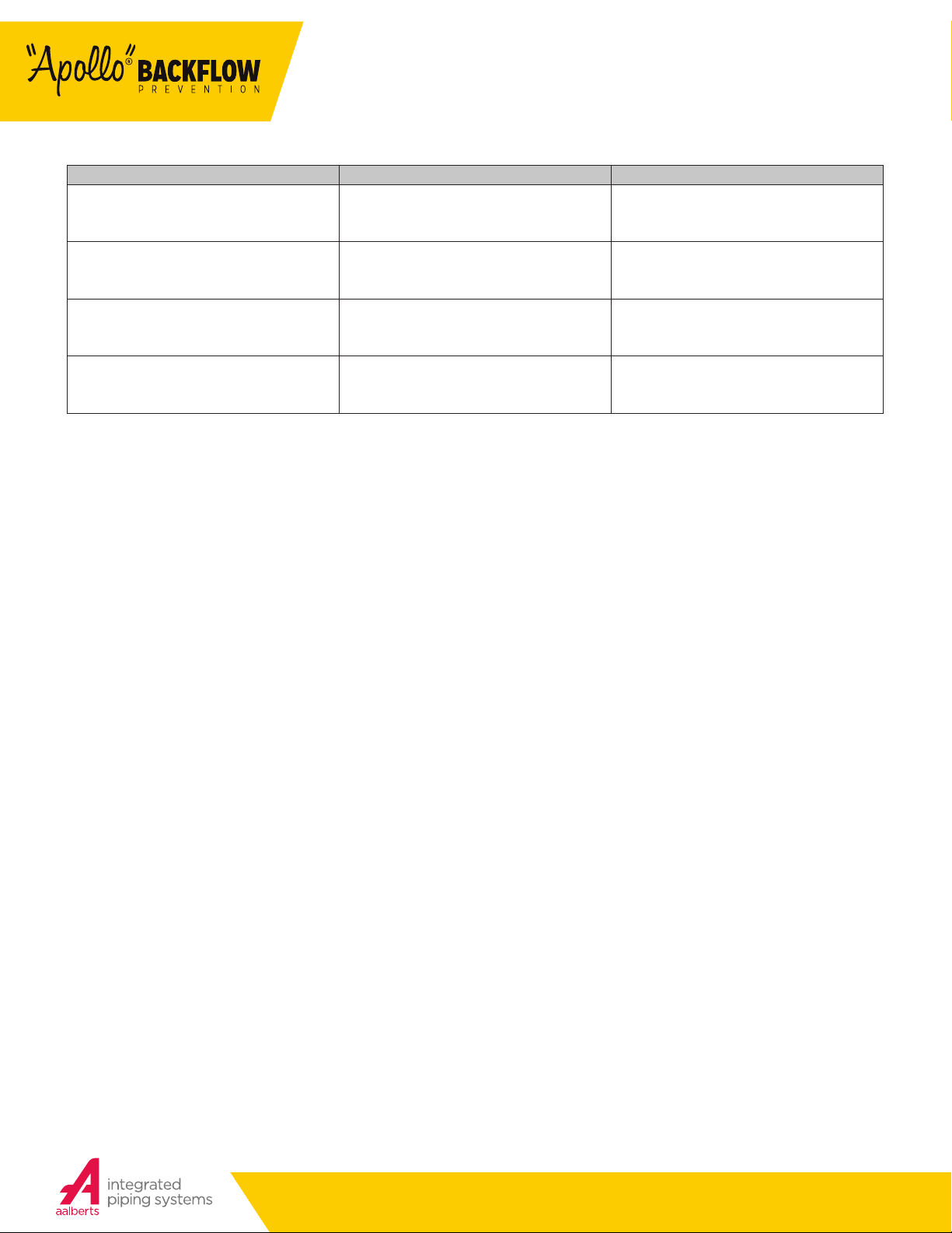
Air inlet fails to open or opens below 1 psig.
BFMMPVB4A
ES1599 REV A
1. Float not moving freely.
2. Float disc sticking to seat.
1. Inspect for fouling debris or deposits.
2. Clean float seat area on bonnet and replace
float disc/turn disc over.
Air inlet fails to close.
Check valve fails to hold 1 psig.
Water continues to flow from test cock #2 during
test #2.
1. Float not moving freely.
2. Float disc fouled with debris.
1. Check valve fouled with debris.
2. Check valve seat damage.
1. #2 shut-o valve not closed completely.
2. Test equipment improperly installed.
1. Inspect for fouling debris or deposits.
2. Clean float seat area on bonnet and remove
debris.
1. Remove, clean, or replace check valve.
2. Replace seat
1. Close #1 shut-o valve.
IV. MAINTENANCE INSTRUCTIONS
A. DISASSEMBLY
1. Close #2 shut-o valve, then close #1 shut-o valve.
2. Bleed pressure from device by opening test cocks #1 and #2.
3. Remove the air inlet canopy by loosening the two screws, rotating the canopy to the left, and lifting up.
4. Unscrew and remove the bonnet and float assembly. DO NOT USE CANOPY TO UNSCREW BONNET! DAMAGE TO THE CANOPY MAY OCCUR.
5. Remove float cage.
6. Push down and turn the spring retainer 90° to remove. Remove the spring. Remove the poppet from the check seat.
CAUTION: Do not use pliers or other tools, which may damage or scratch the plastic stem.
7. Holding the poppet assembly in one hand, remove screw and retaining washer.
8. Remove the seat disc.
9. All parts should be carefully inspected for any damage or excessive wear and thoroughly rinsed in clean water prior to reassembly. Replace worn
parts as necessary.
10. Normally, the check seat need not be removed. If removal is required, rock it back and forth while pulling outward.
B. ASSEMBLY
1. If the check seat was removed, install the new o-ring and lubricate with Apollo® supplied lubricant, DOW 111, or equal. Line up the seat with the
bore and push it firmly into place.
2. Install new disc in poppet and secure with washer and screw.
3. Place and center the poppet assembly in the check seat.
4. Install the spring onto the poppet, ensure that it is centered around the raised spring pad.
5. Install the spring retainer onto the spring by pushing down into the grooves of the check seat and turning 90°. Ensure spring retainer pops up
about .1” and locks into the lugs.
CAUTION: Ensure the spring retainer orientation matches that in the parts list drawing or the device’s flow will be significantly restricted.
6. Install float cage and float. See drawing for correct orientation.
7. Apply a thin coat of Apollo®® supplied lubricant, DOW 111 or equal onto o-ring, screw bonnet into body.
8. Test device to insure proper installation.
9. Install air inlet canopy.
Customer Service (704) 841-6000
backflow.apollovalves.com
5
Page 6

INSTALLATION, OPERATION &
MAINTENANCE MANUAL
V. TESTING PROCEDURES
Equipment Required: Dierential Pressure Test Kits 40-200-TKU or 40-200 TK5U.
NOTE: These procedures may or may not be approved in all jurisdictions. Consult your local water purveyor for acceptable test procedures.
TEST SETUP
1. Obtain permission to shut o the water supply.
2. Determine the direction of flow.
3. Identify and “blow out” test cocks and install appropriate adapters (if necessary).
4. All test kit valves are closed.
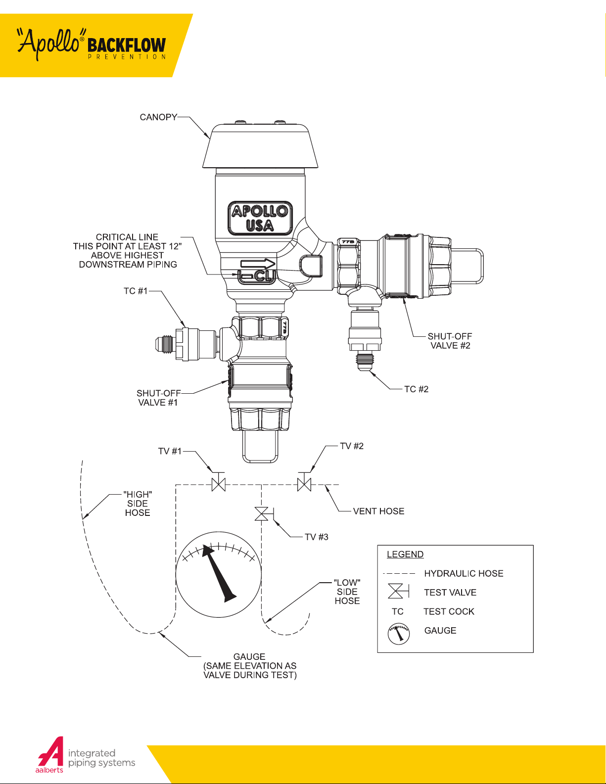
IMPORTANT: THE TEST KIT AND HOSE MUST BE HELD AT THE SAME LEVEL AS THE PVB DURING
TESTS 1 AND 2.
TEST NO. 1
DOES THE AIR INLET VALVE OPEN WHEN THE PRESSURE IN THE BODY IS AT LEAST 1 PSI ABOVE
ATMOSPHERIC PRESSURE? IS THE AIR INLET VALVE FULLY OPEN WHEN WATER DRAINS FROM THE
BODY?
1. Remove air inlet valve canopy.
2. Connect a hose between test cock #2 and the high side connection on the test kit. Open test cock #2.
3. Bleed the high side by opening bleed high valve (high and bypass valves on a 3-valve test kit). Close the bleed high valve (high valve on 3-valve
test kit).
4. Close #2 shut o valve, and then close #1 shut o valve.
5. SLOWLY open the bleed high valve (high valve on 3-valve test kit) no more than 1/4 turn, dropping the pressure slowly.
6. Record pressure reading when the air inlet valve opens. It should be 1PSI or higher. If the air inlet valve does not open go to step #8.
7. Fully open the bleed high valve (high valve on 3-valve test kit). Check if the air inlet valve is fully open. Close the bleed high valve (high valve on a
3-valve test kit).
8. Close test cock #2. Disconnect the high hose from test cock #2. Open shut o valve #1. Proceed to Test #2.
9. The #1 shut o valve is leaking. Open and close shut o valve #1 to attempt a better seal. Repeat step #6. If step #6 cannot be passed go to step
#9.
10. SLOWLY open test cock #1 until the gauge reading starts dropping. Record the pressure reading when the air inlet valve opens. (It should be 1 PSI
or higher.) Return to step #7. If test cock #1 is fully open and the air inlet valve has not opened, Shut o valve #1 must be repaired or replaced.
TEST NO. 2
DOES THE CHECK VALVE SEAL IN THE DIRECTION OF FLOW WHEN THE INLET PRESSURE IS 1 PSI
ABOVE ATMOSPHERIC PRESSURE? – PRESSURE TIGHT #1 SHUT-OFF VALVE
1. Connect high side hose to test cock #1. Open test cock #1.
2. Bleed the high side by opening the bleed high valve (high valve on a 3-valve test kit). Close the bleed high valve (high valve on a 3-valve test kit).
3. Close shut o valve #1 then open test cock #2.
4. Record the gauge reading when water stops draining from test cock #2. It should be 1 PSI or higher.
5. Close all test cocks. Open both shut o valves. Remove all test equipment. Replace air inlet valve canopy. Drain test kit.
TEST NO. 3
LEAKY #1 SHUT-OFF VALVE
1. Connect a bleed-o valve assembly (not included with test kit) to test cock #1.
2. Connect high side hose to the bleed-o valve. Open test cock #1.
3. Bleed the high side by opening the bleed high valve (high valve on a 3-valve test kit). Close the bleed high valve (high valve on a 3-valve test kit).
4. Close shut o valve #1, then open test cock #2.
5. Slowly open the bleed-o valve at test cock #1 until the water flow stops draining from test cock #2. Record the gauge reading. (It should be 1 PSI
or higher.) If the flow from test cock #2 cannot be stopped by opening the bleed-o valve, shut o valve #1 must be repaired or replaced.
6. Close all test cocks. Open both shut o valves. Remove all test equipment. Replace air inlet valve canopy. Drain test kit.
6
Customer Service (704) 841-6000
backflow.apollovalves.com
Page 7
V. TESTING PROCEDURES
FIGURE 3
BFMMPVB4A
ES1599 REV A
Customer Service (704) 841-6000
backflow.apollovalves.com
7
Page 8
INSTALLATION, OPERATION &
MAINTENANCE MANUAL
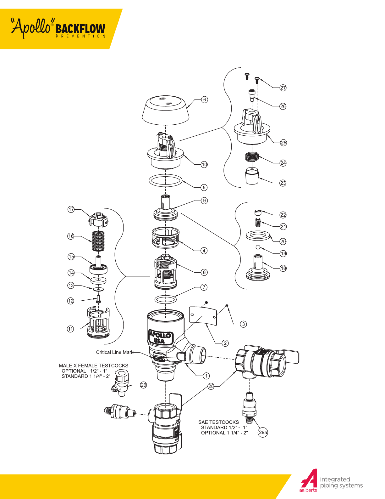
PART NUMBER DIAGRAM - 1/2” - 2”
FIGURE 4
8
Customer Service (704) 841-6000
backflow.apollovalves.com
Page 9
BFMMPVB4A
ES1599 REV A
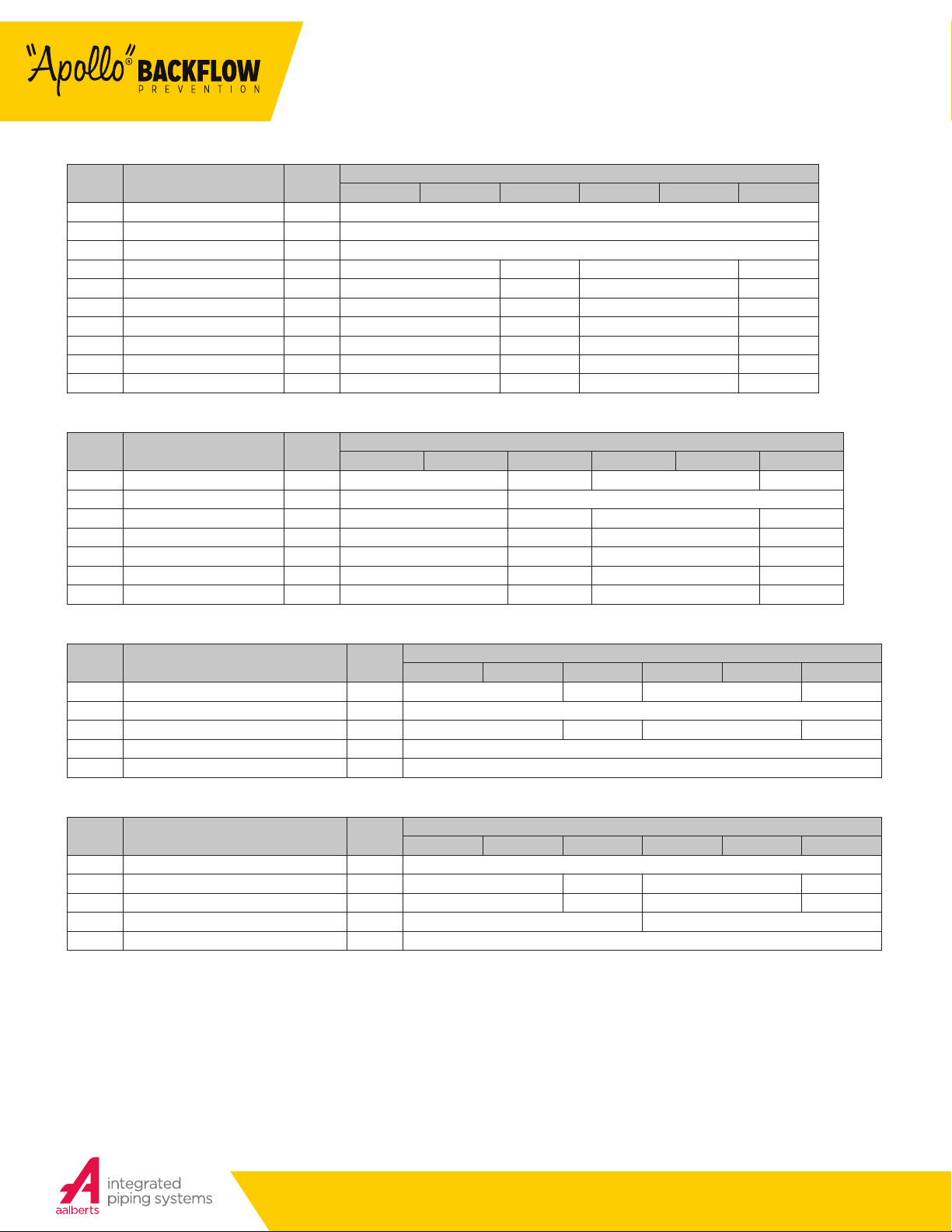
PVB4A PARTS LIST
ITEM # DESCRIPTION QT Y.
1 Body 1 Consult Factory
2 Label Plate 1 Consult Factory
3 Label Plate Tacks 2 I-2614-00
4 Float Cage 1 F-3844- 00 F-3840-00 F-3870-00 F-3873-00
5 Bonnet O-Ring 1 D-4812-00 D-4883-00 D-48 87-0 0 D-4858-00
6 Canopy 1 F-38 42-00 F-3838-00 F-3868-00 F-3871-00
7 Check Module O-Ring 1 D-4880-00 D-4744-00 D-4882-00 D-4884-00
8 Check Mod S-Assy (see below) 1 W-9075-05 W-9003-05 W-9 074 -05 W-9159-05
9 Float FR S-Assy (see below) 1 W-9101-05 W-9096-05 W-9178-05 W-9181-05
10 Bonnet S-Assy (see below) 1 W-9099- 05 W-9094-05 W-9176-05 W-9179 -05
Individual parts are only available for bulk sales. Please refer to the appropriate repair kits on page 11.
1/2” 3/4” 1” 1-1/4” 1-1/2” 2”
CHECK MODULE SUB-ASSEMBLY PARTS LIST
ITEM # DESCRIPTION QT Y.
11 Check Seat 1 L- 78 1 5 -0 0 L-7 72 7- 00 L- 7 8 13 -0 0 L-7979-00
12 Screw 1 B-3279-00 B-1750-00
13 Disc Retaining Washer 1 E-2372-00 E-28 41-0 0 E-2933-00 E-2860-00
14 Seat Disc 1 D-4771-00 D- 4743- 00 D-4770-00 D-4853-00
15 Poppet 1 K-449 1- 00 K-4 471- 00 K- 44 83-0 0 K-4511- 00
16 Spring 1 A-2505-00 A-2 503-00 A-2510-00 A-2511-00
17 Spring Retainer 1 L-7814- 00 L-7 72 6- 00 L-7 81 2- 00 L-7980-00
Individual parts are only available for bulk sales. Please refer to the appropriate repair kits on page 11.
1/2” 3/4” 1” 1-1/4” 1-1/2” 2”
FLOAT, FREEZE RESISTANT SUB-ASSEMBLY PARTS LIST
ITEM # DESCRIPTION QT Y.
18 Float 1 K-4508- 00 K-4496 -00 K-4516-0 0 K-45 18-00
19 Ball 1 I-6183-00
20 Seal 1 D-4811-00 D-4784-00 D-4859-00 D-4860-00
21 Spring 1 A-1968-00
22 Spring Retainer 1 B-3214 -00
Individual parts are only available for bulk sales. Please refer to the appropriate repair kits on page 11.
1/2” 3/4” 1” 1-1/4” 1-1/2” 2”
BONNET SUB-ASSEMBLY PARTS LIST
ITEM # DESCRIPTION QT Y.
23 Float Guide 1 K-4494-00
24 Float Spring 1 A-2491 -00 A-24 89 -0 0 A-2501- 00 A-2502-00
25 Valve Bonnet 1 F-3 843-00 F-3839-00 F-3869-00 F-3872-00
26 Float Guide Screw 1 B-3213-00 B-3281-0 0
27 Canopy Screws 2 B-3232-00
Individual parts are only available for bulk sales. Please refer to the appropriate repair kits on page 11.
1/2” 3/4” 1” 1-1/4” 1-1/2” 2”
PART NUMBER
PART NUMBER
PART NUMBER
PART NUMBER
Customer Service (704) 841-6000
backflow.apollovalves.com
9
Page 10
INSTALLATION, OPERATION &
MAINTENANCE MANUAL
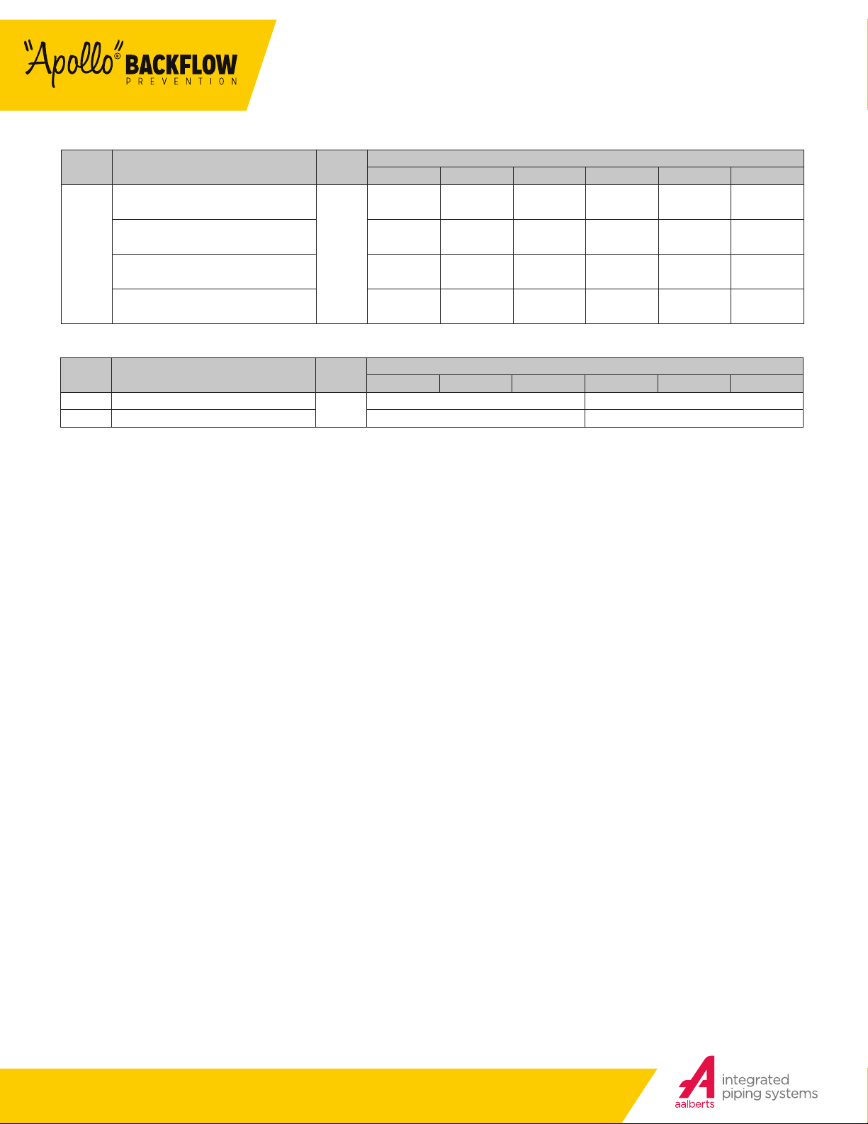
INLET AND OUTLET SHUT-OFF VALVES
ITEM # DESCRIPTION QT Y.
A2 Inlet and Outlet NPT Ball Valve
with “T” Handle (Standard) (81 Metal)
A4 Inlet and Outlet Union Ball Valve
28
w/ “T” Handle (Option) (81 Metal)
2
A2 Inlet and Outlet NPT Ball Valve
with “T” Handle (Standard) (Lead Free)
A4 Inlet and Outlet Union Ball Valve
w/ “T” Handle (Option) (Lead Free)
1/2” 3/4” 1” 1-1/4” 1-1/2” 2”
91B-103-85 91B-104-83 91B-105-83 91B-106-83 91B-1 07-83 91B-108-83
Not Available W-2705-05 W-2707-05 W-2709- 05 W-2710-05 W-27 11-05
Not Available 91BLF-104-83 91BLF-105-83 Not Available Not Available Not Available
Not Available W-2706- 05 W-2708-05 Not Available Not Available Not Available
TEST COCKS
ITEM # DESCRIPTION QT Y.
29 Test Cock M x F (LF)
29a Test Cock SAE (LF) 78LF-292-01 (Standard) 78LF-293-01 (Optional)
2
1/2” 3/4” 1” 1-1/4” 1-1/2” 2”
78LF-290-01 (Optional) 78LF-291-01 (Standard)
PART NUMBER
PART NUMBER
10
Customer Service (704) 841-6000
backflow.apollovalves.com
Page 11
BFMMPVB4A
ES1599 REV A
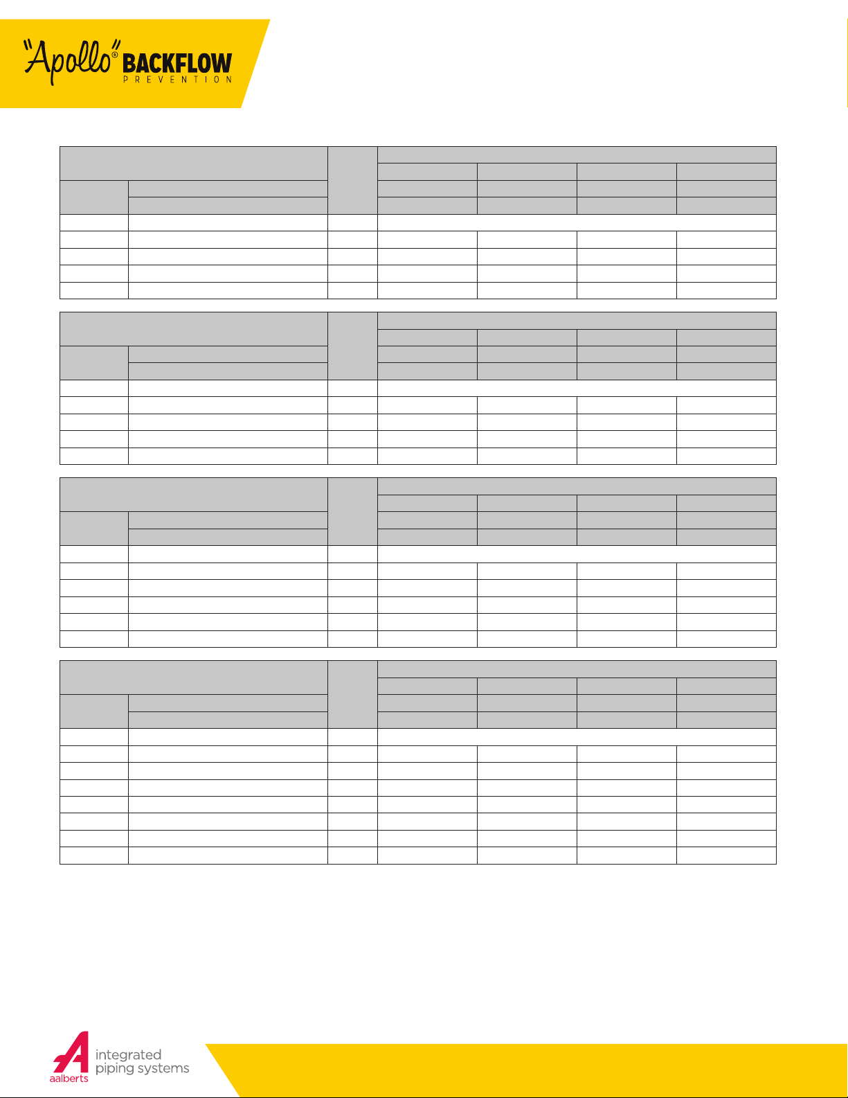
REPAIR KITS PVB4A - 1/2” – 2”
PVB CHECK COMPLETE KIT
ITEM #
not shown O-Ring Lubricant I-9016-00
8 Check Module S-Assy 1 W-9075-05 W-9003-05 W-9 074-05 W-9159 -05
7 Check Module O-Ring 1 D-4880-00 D-4744-00 D-4882- 00 D-4884-00
5 Bonnet O -Ring (for PVB) 1 D-4812-00 D-4883-00 D-4887-0 0 D-4858-00
ex tra p art (s) Cap O-Ring (for DC/RP) 1 D-4881-00 D-4812- 00 D-4884-00 D-4885-00
REPAIR KIT MODE L NUMBER RK4A12CMC RK4A34CMC RK4A1CMC RK4A112CMC
ORDERING NUMBER 4A-003-02 4A-004-02 4A-005-02 4A- 007- 02
QTY
1/2” – 3/4” 1” 1-1/4” – 1-1/2” 2”
SIZE
PVB FLOAT AND CHECK RUBBER KIT
ITEM #
not shown O-Ring Lubricant I-9016-00
5 Bonnet O-Ring 1 D-4812-00 D-4883-00 D-4887-00 D-4858-00
20 Float Seat Disc 1 D-4811-00 D-4784-00 D-4859 -00 D-4860-00
14 Check Module Seat Disc 1 D-4771-00 D-4743-00 D-4770-00 D-4853-00
7 Check Module O-Ring 1 D-4880-00 D-4744-00 D-4882- 00 D-4884-00
COMPLETE KIT, TOP HALF OF PVB
ITEM #
not shown O-Ring Lubricant I-9016-00
5 Bonnet O-Ring 1 D-4812-00 D-4883-00 D-4887-00 D-4858-00
10 Bonnet S-Assy 1 W-9099-05 W-9094-05 W-9176-05 W-9179-05
9 Float S-Assy 1 W-9101-05 W-909 6-05 W-9178-05 W-9181-05
4 Float Cage 1 F-3844-00 F-3840-00 F-3870-00 F-3873-00
6 Canopy 1 F-3842-00 F-3838-00 F-3868-00 F-3871-00
ITEM #
not shown O-Ring Lubricant I-9016-00
8 Check Module S-Assy 1 W-9075-05 W-9003-05 W-9 074-05 W-9159 -05
7 Check Module O-Ring 1 D-4880-00 D-4744-00 D-4882- 00 D-4884-00
5 Bonnet O-Ring 1 D-4812-00 D-4883-00 D-4887-00 D-4858-00
10 Bonnet S-Assy 1 W-9099-05 W-9094-05 W-9176-05 W-9179-05
9 Float S-Assy 1 W-9101-05 W-909 6-05 W-9178-05 W-9181-05
4 Float Cage 1 F-3844-00 F-3840-00 F-3870-00 F-3873-00
6 Canopy 1 F-3842-00 F-3838-00 F-3868-00 F-3871-00
REPAIR KIT MODE L NUMBER RK4A34PVBR RK4A1PVBR RK4A112PVBR RK4A2PVBR
ORDERING NUMBER 4A-004-06 4A-005-06 4A-007-06 4A-008-06
PVB FLOAT AND BONNET
REPAIR KIT MODE L NUMBER RK4A34PVBFB RK4A1PVBFB RK4A112PVBFB RK4A2PVBFB
ORDERING NUMBER 4A-004-07 4A-005-07 4A- 007-07 4A-008-07
PVB COMPLETE INTERNALS KIT
REPAIR KIT MODE L NUMBER RK4A34T PVB R K4A1T PVB RK4A112TPVB R K4A2TPVB
ORDERING NUMBER 4A-004-11 4A-005-11 4A-007-11 4A-008-11
QTY
QTY
QTY
1/2” – 3/4” 1” 1-1/4” – 1-1/2” 2”
1/2” – 3/4” 1” 1-1/4” – 1-1/2” 2”
1/2” – 3/4” 1” 1-1/4” – 1-1/2” 2”
SIZE
SIZE
SIZE
Customer Service (704) 841-6000
backflow.apollovalves.com
11
Page 12

PHONE: (704) 841-6000
FAX: (704) 841-6020
Regional Management List
now available online at:
http://conbra.co/rmlist
ES1599 IOM BFMMPVB4A rev.a 8/17
Customer Service (704) 841-60 00
www.apollovalves.com
 Loading...