

Page 1
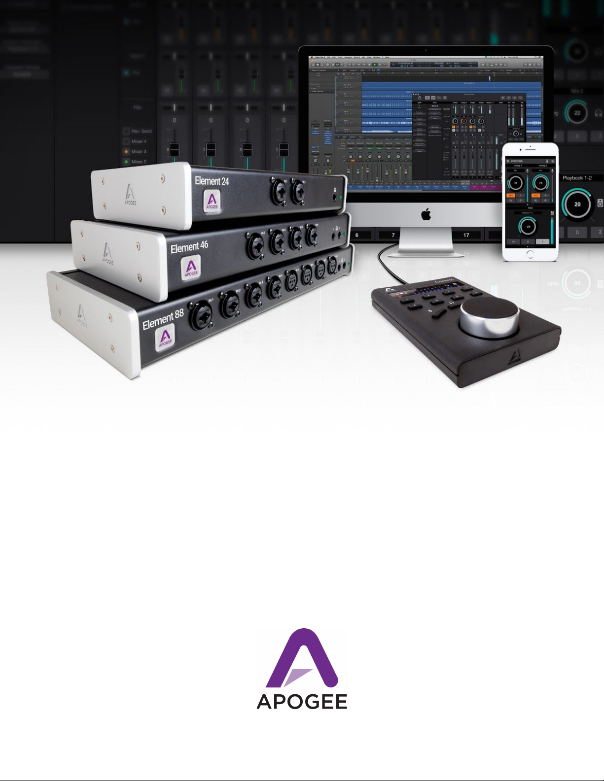
Apogee Element Series
User’s Guide v1.1, December 2016
U
1
Page 2

Apogee Element Series User’s Guide
Contents
Overview 3
Introduction 3
Legendary Sound Quality. The Power of Thunderbolt. Elegant Simplicity. 3
The Elements of Excellent Audio 3
Package Contents 4
Register your product 4
Element Panel Tours 5
Setup 6
System Requirements 6
Download and Install Element Software package 6
Connect Element to Your Computer 7
Update Element’s Firmware 8
Element Control 9
Element Control Mac Software 9
Essentials Window 10
Primary Window 16
Remote Window 17
Hover Help Window 19
Menu Bar Menus 20
Apogee Control iOS App 23
Snapshots & Examples 24
Getting Started Snapshot Template 25
How Element Control Input Channels appear in your Recording Program: 26
How Element Control Outputs work with your Recording Program: 27
How to get a separate mix to the headphones than from the speaker outputs: 28
Essentials Snapshot Template 30
Direct Monitoring Snapshot Template 31
Using the Direct Monitor Snapshot Template with your Recording Program 33
Full Functionality Snapshot Template 34
Vocal Overdub Snapshot Template 35
A/D Expander Snapshot Template 39
Working with a Multiple Element Interface Setup 40
Connecting a Multiple Element Interface System: 40
The Multiple Element Interface System in Use 41
Additional Support 42
Specifications 43
Warranty Information and Legal Notices 44
Declarations of Conformity 44
2
Page 3
Apogee Element Series User’s Guide
Overview
Introduction
Legendary Sound Quality. The Power of Thunderbolt. Elegant Simplicity.
Apogee’s Element 24, 46 and 88 are Thunderbolt audio I/O boxes for Mac. The Element Series takes the best of cutting-edge
Apogee gear like Symphony I/O Mk II, Ensemble Thunderbolt and Groove and puts it into simple form factors. With
streamlined hardware features and advanced software control, the Element series delivers ultimate recording quality and
performance at unprecedented prices.
The Elements of Excellent Audio
Analog to Digital Conversion
A high-quality A/D converter is critical for capturing every detail of your recordings into your computer.
The Element series features some of the best Apogee A/D conversion. Recording through an Element
ensures you will minimize unwanted noise and maximize the signal quality. Your tracks will sound
amazing and mixing your project will be easier.
Microphone Preamps
Whether you are recording powerful drums, dynamic vocals or delicate strings, you need a premium mic
preamp to capture the finest details of the performance. The Element Series mic preamps feature
Apogee’s Advanced Stepped Gain Architecture™. This analog circuit is designed to dynamically
optimize across a gain range of 0-75dB to provide superior bandwidth and low distortion.
Digital to Analog Conversion
With a high-quality D/A converter, you will hear more definition in each track and virtual instrument. This
clarity makes it easier for you to make precise adjustments and achieve the ideal balance when mixing
your music. When you listen to your sessions through an Element, tracks will blend more harmoniously
and mixing will be easier. The high end will sound crisp and clear and the low end will be tight and well
defined.
Clocking
An audio interface relies on a clock source like an orchestra relies on a conductor. A digital audio clock
provides a timing signal to all the parts of a digital audio system so that each part of the AD/DA process
may be synchronized. Element has its own built-in clock source and provides professional Word Clock IN
and OUT for syncing with other digital audio gear. Use Element as the master clock to take advantage of
Apogee’s superior built-in clocking technology.
Thunderbolt Connectivity
The Element Series Thunderbolt driver offers incredible low-latency performance (1.41 ms round-trip)
and rock-solid stability. Apogee’s custom driver uses less of your computer’s CPU power with the help of
Direct Memory Access (DMA) technology. This allows you to run more plugins and monitor through your
DAW at a low buffer setting. Element’s low latency driver means you don’t have to choose between
power and speed.
3
Page 4
Apogee Element Series User’s Guide
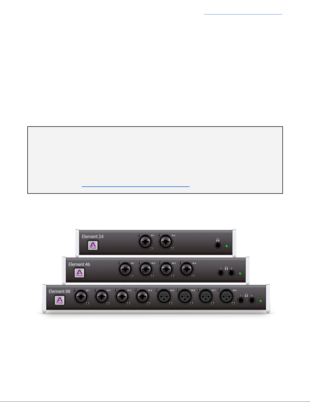
Apogee Element 24
Universal Power Supply with
standard 3 pin-IEC cable
Quick Start Guide
Warranty Booklet
Apogee Element 46
Universal Power Supply with
standard 3 pin-IEC cable
Quick Start Guide
Warranty Booklet
Apogee Element 88
Rack mounting kit
Universal Power Supply with
standard 3 pin-IEC cable
Quick Start Guide
Warranty Booklet
Register your product
● Access Apogee’s expert Technical Support for free
● Receive important product update information by email
● Take the Customer Satisfaction Survey for a chance to win Apogee gear!
Register Now: www.apogeedigital.com/support/register
Package Contents
The following items are included with your Element Series Interface
4
Page 5
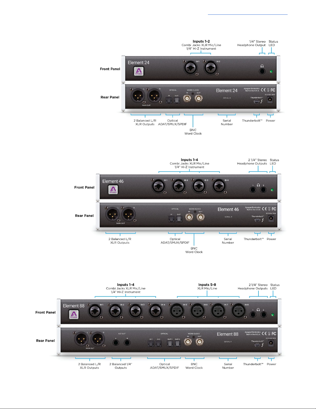
Element 24 Panel Tour
Element 46 Panel Tour
Apogee Element Series User’s Guide
Element 88 Panel Tour
5
Page 6
Apogee Element Series User’s Guide
Setup
System Requirements
● Mac OS X 10.10 or greater
● Thunderbolt™-equipped Mac
● 4GB minimum RAM, 8GB Recommended
Download and Install Element Software package
Before Element will work with the computer, special software must be installed. Always get the latest version of the software
from the apogee website:
www.apogeedigital.com/support/element
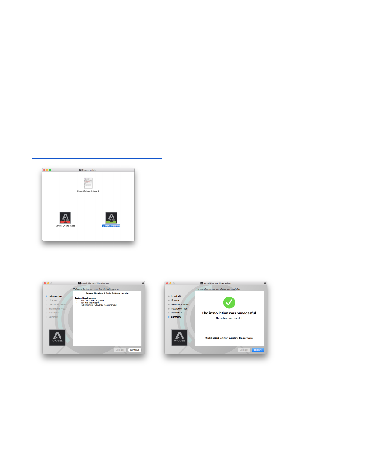
The download comes in the form of a .dmg file. Open it to view the contents.
Inside you will find three items:
● Element Release Notes.pdf
● Element Uninstaller.app
● Element Installer.pkg
Double-click to launch the Element Installer.pkg. A dialog box will appear with a series of steps to proceed. Follow the
prompts to complete the installation. You will be required to restart your computer.
As a result of the software install:
● Element Control software is placed in the Mac’s Applications folder
● When connected, the Element Thunderbolt interface appears as an audio input/output device in Mac System
Preferences > Sound
● Element Firmware Updater.app is placed in the Mac’s Applications > Utilities folder.
6
Page 7
Connect Element to Your Computer
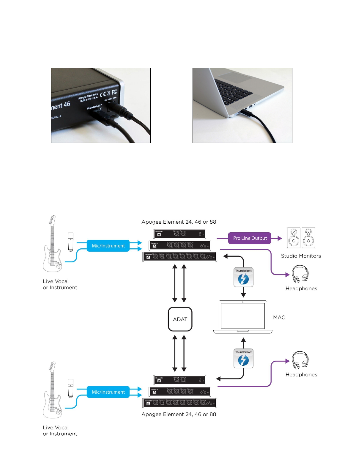
1. Connect the Power Supply to Element.
2. Connect Element to your Mac using a Thunderbolt cable.
If connecting a Second Element
Apogee Element Series User’s Guide
1. Connect the Power Supply to Element
2. Connect Element to a second Thunderbolt port on your Mac.
3. Connect optical cables from the Optical Out of one Element, to the Optical In of the second Element.
● If second unit is Element 24 & 46 - Two optical cables required
● If connecting two Element 88 units - Four optical cables required
7
Page 8
Apogee Element Series User’s Guide
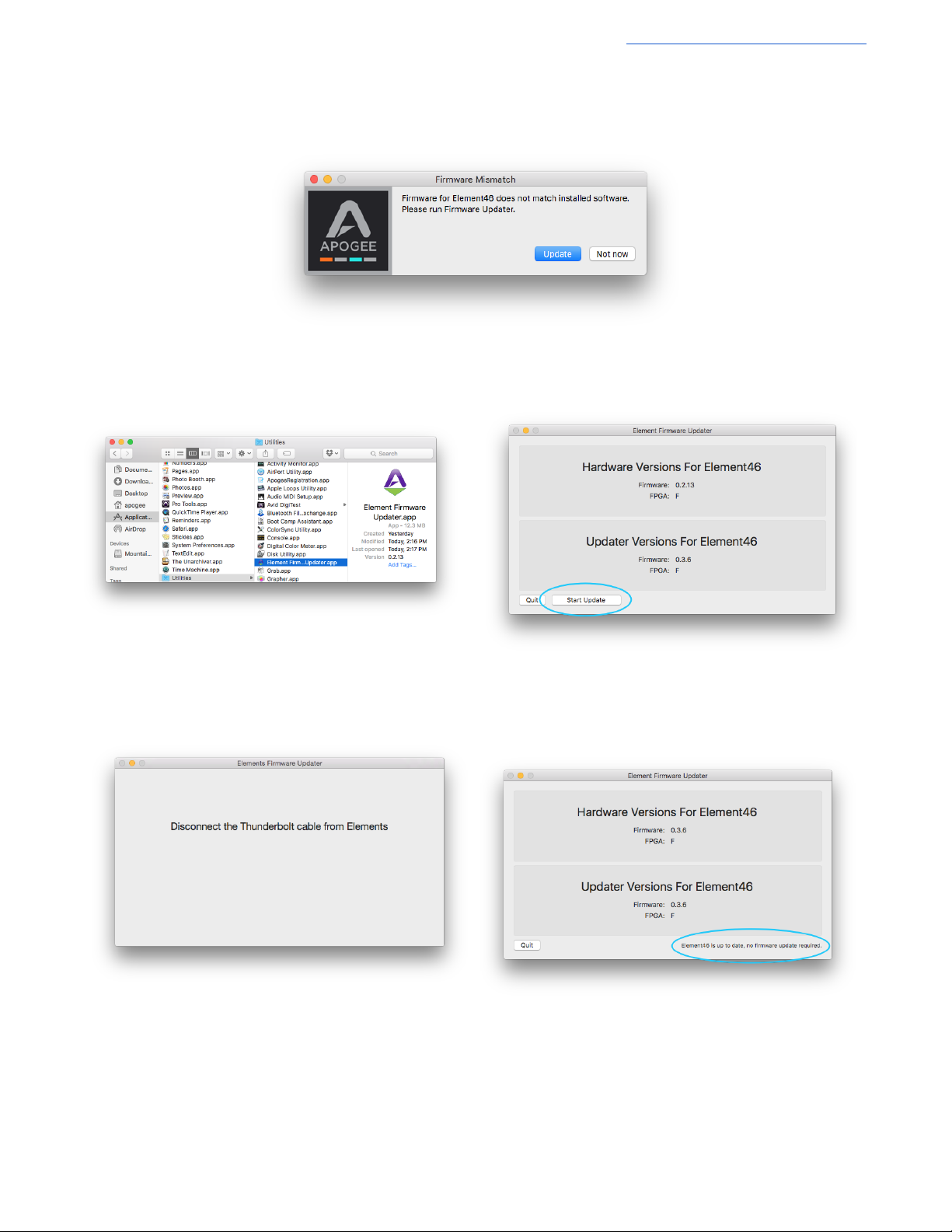
1. Click Update, or manually open the Element
Firmware Updater.app from your computer’s
Applications > Utilities folder.
2. Make sure only one Element is connected to the
Mac. Then click Start Update.
3. Follow any prompts that may appear.
4. When it says Element is up to date, you can quit
the updater.
Update Element’s Firmware
When first connecting Element to your computer, you may be prompted to update the Firmware:
8
Page 9
Apogee Element Series User’s Guide
Element Control
Control of your Apogee Element Thunderbolt interface is available through a Mac software app, an iOS control app, or the
Remote control surface. Each provides it’s own unique set of controls and features.
Element Control Mac Software
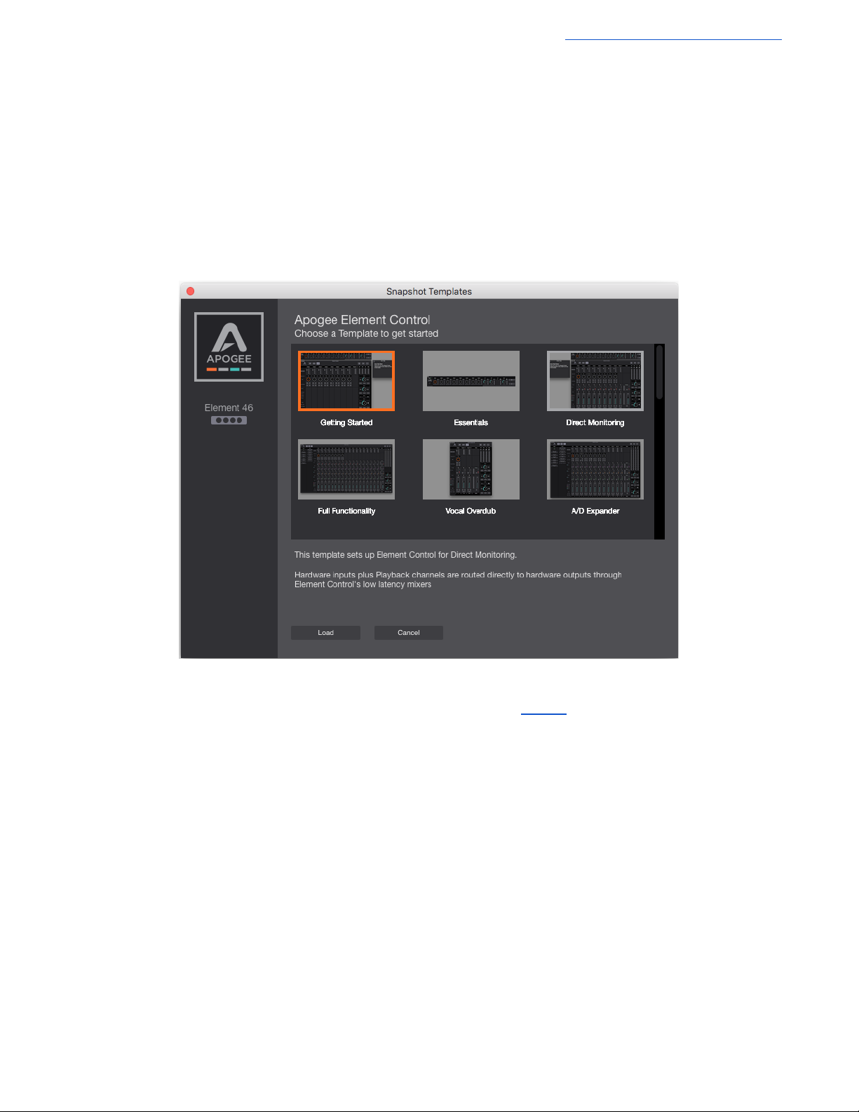
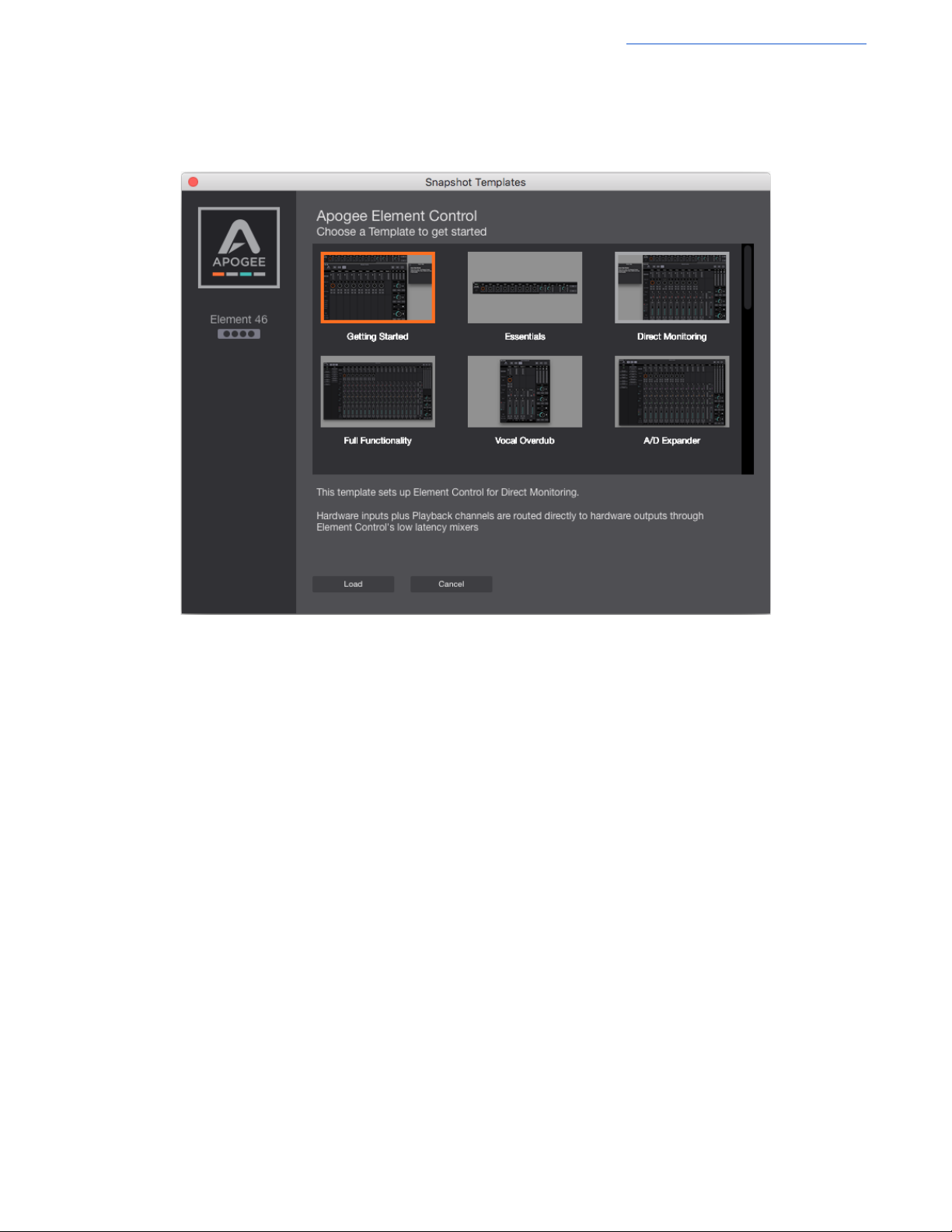
When Element Control for Mac software is opened, you are presented with a Snapshot Template chooser.
Each Snapshot Template is a starting point that provides the most common feature set needed for various workflows. These
default Snapshot Templates and examples of their use are explained further on page 24. A snapshot can be customized to
your specific needs and saved as a user-snapshot. Here is an explanation of all the features and components of Element
Control Software:
Element Control consists of four windows:
1. Essentials
2. Primary
3. Hover Help
4. Remote
9
Page 10
Apogee Element Series User’s Guide
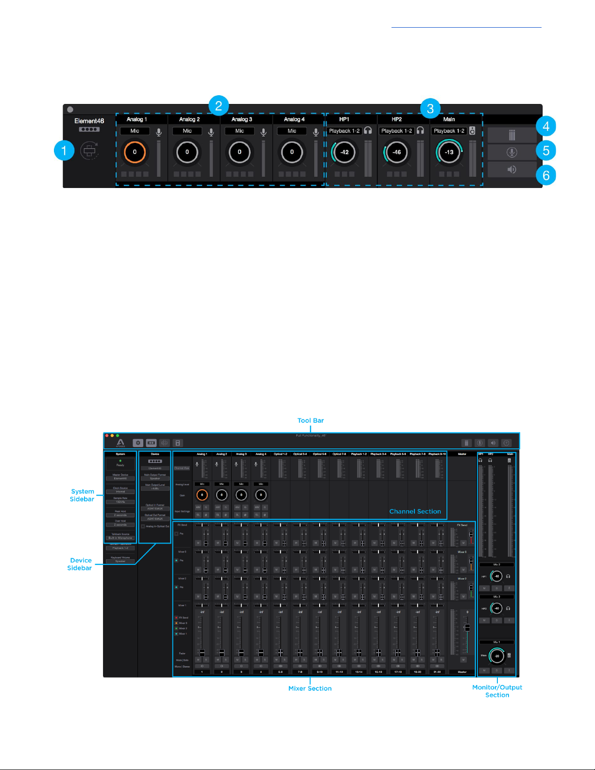
Essentials Window
This window provides simple and compact controls for Input Channels and Outputs. It’s orientation can be changed between
vertical and horizontal so that it can be placed to the side or end of your recording software.
1. Orientation Button - Switches the Essentials window between horizontal and vertical view.
2. Analog Input Channels - Provides settings for the analog inputs.
● The buttons at the bottom correspond to the Input Channel Settings: Phantom Power (48V), Group (G), Soft
Limit (SL), and Polarity Invert (⌀)
3. Outputs - Headphones and speaker outputs settings are provided.
● The buttons at the bottom correspond to the Output controls: Mute (M), Dimminish (D), Sum-to-Mono (Σ)
4. Clear Meters - Clear the Peak or Hold indicators from the level meters.
5. Talkback - Engages talkback to communicate with artists wearing headphones. Set the Talkback source and
destination in the System Sidebar.
6. Mute All - Mutes Headphones and Speakers outputs of the Element Thunderbolt interface. To unmute, click the
individual headphone or speaker mute buttons.
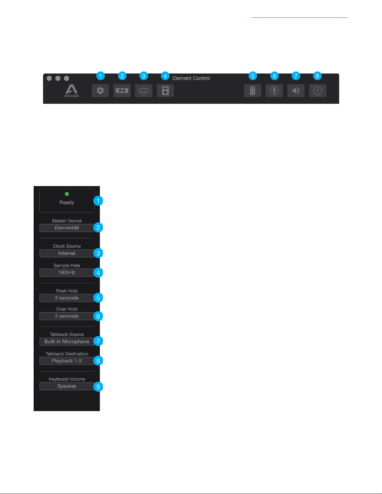
Primary Window
All features and settings of the Element Thunderbolt interface can be controlled from the Primary window. It is broken down
into several sections:
10
Page 11
Apogee Element Series User’s Guide
1. System Sidebar Button
2. Device Sidebar Button
3. Essentials Button
4. Remote Button
5. Clear Meters Button
6. Talkback Button
7. Mute All Button
8. Hover Help Button
Tool Bar
The Tool Bar is always visible at the top of the Primary window. It provides the ability to show/hide the System Sidebar, Device
Sidebar, Essentials window, Remote window and Hover-Help window. It also has buttons for Clear Meters, Talkback and Mute
All outputs.
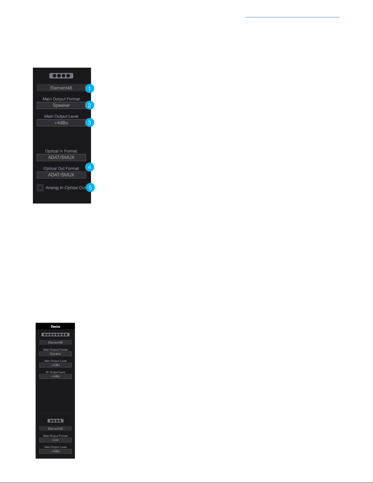
System Sidebar
Provides System-wide settings that apply to your recording system as a whole.
1. System Status Display - This displays the status of the connected hardware.
● Green - System is ready: Hardware is connected and recognized, and the digital
clock is locked to the Clock Source.
● Red - System not ready. Either the hardware is not connected, or the system is not
locked to the Clock Source.
2. Master Device - When two Element interfaces are connected, select one as the Master
Device. The Master Device acts as the clock master, is listed first in your DAW’s hardware
I/O assignment, and includes Output Format functionality on the Main outputs.
3. Clock Source - Selects the system clock source for Element. The following sources may
be selected:
● Internal: Element is clocked from its internal crystal
● Word Clock: Element is clocked from an external word clock signal connected to the
rear panel BNC input
● Optical: Element is clocked from a digital audio input.
4. Sample Rate - Selects Element’s sample rate. In some cases this setting may be
overridden by software running on the computer (i.e. When a DAW session project is
open).
5. Peak Hold - Sets the time that peak indications are held on the level meters.
6. Over Hold - Sets the time that over indicators are held on the level meters.
7. Talkback Source - Select the source of the Talkback Signal. If your Mac is equipped with a
Built-in Mic, select Built-in Mic as the source.
8. Talkback Destination - Set the Playback channel destination for the Talkback signal.
When using the low latency mixer, note that the Talkback signal is routed through the
selected Playback mixer channel.
9. Keyboard Volume - The audio system may be configured so that the Mac keyboard
volume controls set the output level of Element’s speaker or headphone outputs.
11
Page 12
Apogee Element Series User’s Guide
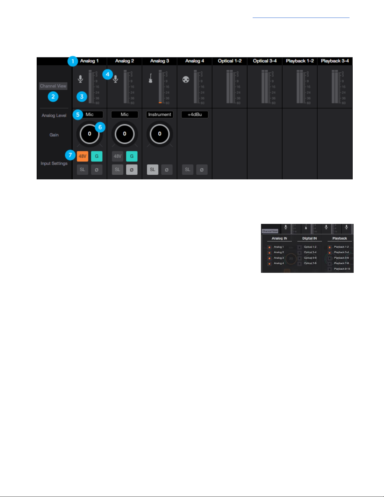
Device Sidebar
The Device Sidebar provides settings that are specific to the Element interface connected to the Mac.
1. Device ID - Identifies the hardware connected to the Mac system.
● Clicking this button causes the displayed hardware to flash it’s status light for three
seconds.
2. Main Output Format - Changes the output to suit what is being connected to the XLR Main
output jacks:
● Speaker - Use this setting when connecting speakers to the Main XLR hardware
outputs
● Line - Use this setting when connecting a mixer or other device with its own volume
control to the Main XLR hardware outputs
3. Main Output Level - Selects the line-level reference for the XLR Main output jacks:
● Choose +4dBu when connecting to “pro” gear with inputs at a +4dBu nominal level.
● Choose -10dBV when connecting to “semi-pro”, hi-fi, or musical instrument gear with
inputs at a -10dBV nominal level.
4. Optical In and Out Format - Sets the digital audio protocol for the optical connectors. Match
the optical format to that of the connecting device:
● SPDIF: The two-channel SPDIF audio format is transmitted or received through the
selected port’s In or Out connections. This format is capable of utilizing a maximum
sample rate of 96kHz.
● ADAT/SMUX: The multi-channel ADAT or SMUX format is transmitted or received
through the selected ports. Capable of 8 channels of digital I/O at sample rates
44.1kHz - 48kHz, and 4 channels of digital I/O at sample rates 88.2kHz - 96kHz.
- *On Element 88, setting the sample rate to 88.2kHz or 96kHz activates the second
set of optical I/O. This provides 4 more channels for a total of 8 channels of digital I/O.
5. Analog In-Optical Out - Enable direct routing from Analog inputs to Optical outputs. When checked, all analog inputs
are passed individually to the Optical outputs.
- On Element 24, signal only appears on ADAT output 1-2.
- On Element 46, signal only appears on ADAT output 1-4.
- On Element 88, signal appears on all ADAT output channels.
Note: When Optical Out Format is set to SPDIF, only inputs 1-2 are transmitted to the optical output 1-2.
Multiple Element Device Sidebar
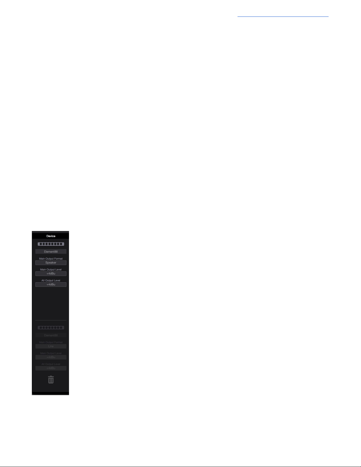
When multiple Element Devices are in use, the Device Sidebar changes to show the Output Format and
Output Level of both devices, while reflecting the loss of the Optical options:
12
Page 13
Apogee Element Series User’s Guide
Channel Section
This portion of the Primary Window displays Channels for Analog input, Digital input, and Playback from audio software.
1. Channel Top Label - Indicates the channels source. Can be renamed by clicking the label and typing a
user-customized label. To restore to the default text, delete the text and press “Return” on your keyboard.
*These labels are transmitted to your DAW
2. Channel View Button - Show the Channel View pop-up to view/hide various
channels.
* Channels are disabled when hidden so audio signal will not pass.
● Analog Input Channels - Corresponds to the physical analog input
connections on your Element interface.
● Optical Input Channels - Corresponds to the physical optical input
connections on your Element interface.
● Playback Channels - Corresponds to the virtual signal path from your Mac’s software outputs.
3. Input Channel Level Meter - Shows the post-gain digital signal level coming into the channel.
4. Input Icon - Shows the input type selected from the Analog Level drop-down
5. Analog Level - Use this drop down menu to choose the analog level for each A/D conversion channel.
● Choose Mic when connecting microphones or direct boxes, or any devices that needs to run through a
microphone preamplifier. -XLR Input only
● Choose Inst when connecting a guitar or keyboard, or any high impedance (Hi-Z) instrument to the 1/4” input
(balanced TRS or unbalanced TS). The signal is sent through a Hi-Z to Low-Z conversion circuit before sent
through the microphone preamplifier circuit.
● Choose +4dBu when connecting to “pro” gear, such as en external mic pre, compressor, or EQ, with outputs
at a +4dBu nominal level.
● Choose -10dBV when connecting to “semi-pro”, hi-fi, or musical instrument gear with outputs at a -10 dBV
nominal level.
6. Gain Control - Use to adjust the gain of the microphone preamp. Not available when the input is set to +4dBu or
-10dBV
13
Page 14
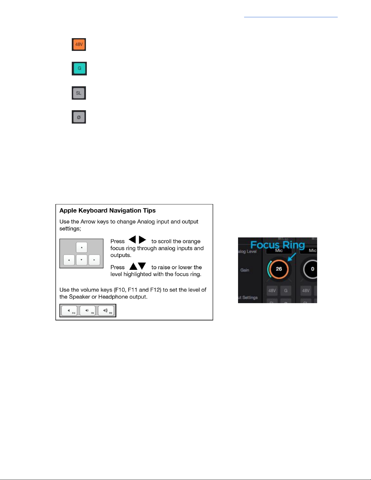
7. Input Settings - Provides options for the various inputs:
● : Use this button to enable 48 volt phantom power on the corresponding Analog In channel. Condenser
mics require 48 volt phantom power to operate.
● Group: The input gain controls of adjacent odd-even channels are adjusted simultaneously. Any level
offsets that exists before inputs are grouped will be preserved after a group is chosen.
● Soft Limit: Select “On” to engage. This option begins to attenuate transient peaks at a threshold of
-4dBfs.
● Polarity Invert: Use this button to invert the polarity of the input signal.
Apogee Element Series User’s Guide
14
Page 15
Apogee Element Series User’s Guide
Mixer Section
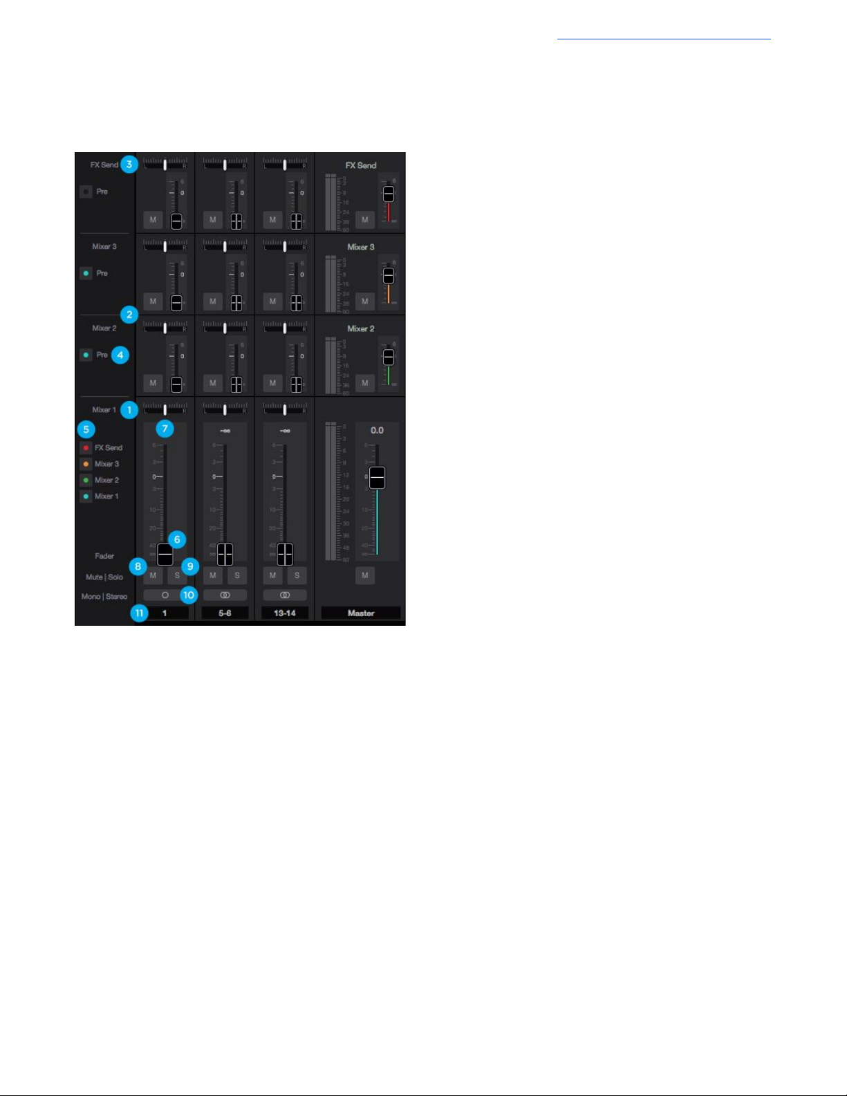
The mixer section provides several Direct Monitor mixers, and a special FX Send mixer for workflows that utilize the
low-latency Direct Monitoring features of your Element Thunderbolt interface.
1. Mixer 1 - Signal from each channel can be sent through
this mixer by raising the corresponding Mixer 1 Channel
Fader.
● This mixer’s Master signal can then be selected as a
source for the Headphones or Speaker outputs,
providing a low-latency direct monitoring signal path.
● This mixer can also be sent back into the computer as
a separate stereo input available in your DAW.
● The faders on this mixer affect the fader send signal
of the other Mixers and FX Send when the Pre Fader
button is not engaged.
2. Mixers 2, 3, 4* - Signal from each channel can be sent
through these mixers by raising the individual Mixer 2, 3,
or 4 Channel Fader.
● This mixer’s Master signal can then be selected as a
source for the Headphones or Speaker outputs
providing a low-latency direct monitoring signal path.
*Note:
Element 24 = 2 mixers available
Element 46 = 3 mixers available
Element 88 = 4 mixers available
3. FX Send - Signal from each channels can be sent through
this mixer by raising the individual FX Send Channel
Fader.
● This Mixer is sent back into the computer where it
shows up as an extra stereo input available in your
DAW. By using this input on an Aux track that has a
Reverb or Delay or other effects plugin, effects can be
applied to a Direct Monitoring situation which would
otherwise be completely dry of effects.
4. Pre Fader Button
● When engaged, the channel signal from the mixer 2, 3, or FX Send mixer is sent to that mixer’s Master fader
based only on that mixer’s channel fader level. This signal level is not affected by the position of the Mixer 1
fader (Pre-fader).
● When not engaged (Post-fader), the channel signal from this mixer will change based on the Mixer 1 fader
position. In other words, moving the Mixer 1 fader on this same channel will alter the signal level going to the
mixer 2, 3 or FX Send mixer master.
5. Mixer View buttons - View or Hide mixers using this button.
*Mixers are always ACTIVE. A mix will continue working even when hidden.
6. Channel Fader - Set the level of the channel signal in the mixer master stereo output.
7. Mixer Channel Pan Control - Set the left-right placement of the channel signal in the mixer master stereo output.
● Option-click to reset the pan to center (0) or Option+Command-click to set all pans in that mixer to center (0).
8. Channel Mute button - Cut the signal routing to the mixer stereo output. Command-click to cut all channels
15
Page 16
Apogee Element Series User’s Guide
Note: Engage Solo-Safe mode on a channel by Control-Clicking the Solo button on a channel. This prevents this
channel from being muted when another channel in the mixer has solo engaged.
A solo-safe engaged track will display a colored “S” within the Solo button
9. Channel Solo button - Mute all channels that do not have this solo button engaged in this mixer. Command-click to
solo all channels.
10. Channel Mono/Stereo button - Set the channel for a mono or stereo signal path. When set to stereo, odd-even
adjacent channels are combined.
● To group input settings set each channel’s Input Gain to 0dB, push the Group button, and then set the channel to
Stereo.
● To adjust a stereo channels individual input’s settings, use the arrow buttons that appear next to the Analog
Level Setting.
11. Channel Aux Label - This secondary label is a convenient way to enter session-specific information, such as the
performer whose input appears on the channel. This label is not transmitted to the audio software (DAW).
Monitor/Output Section
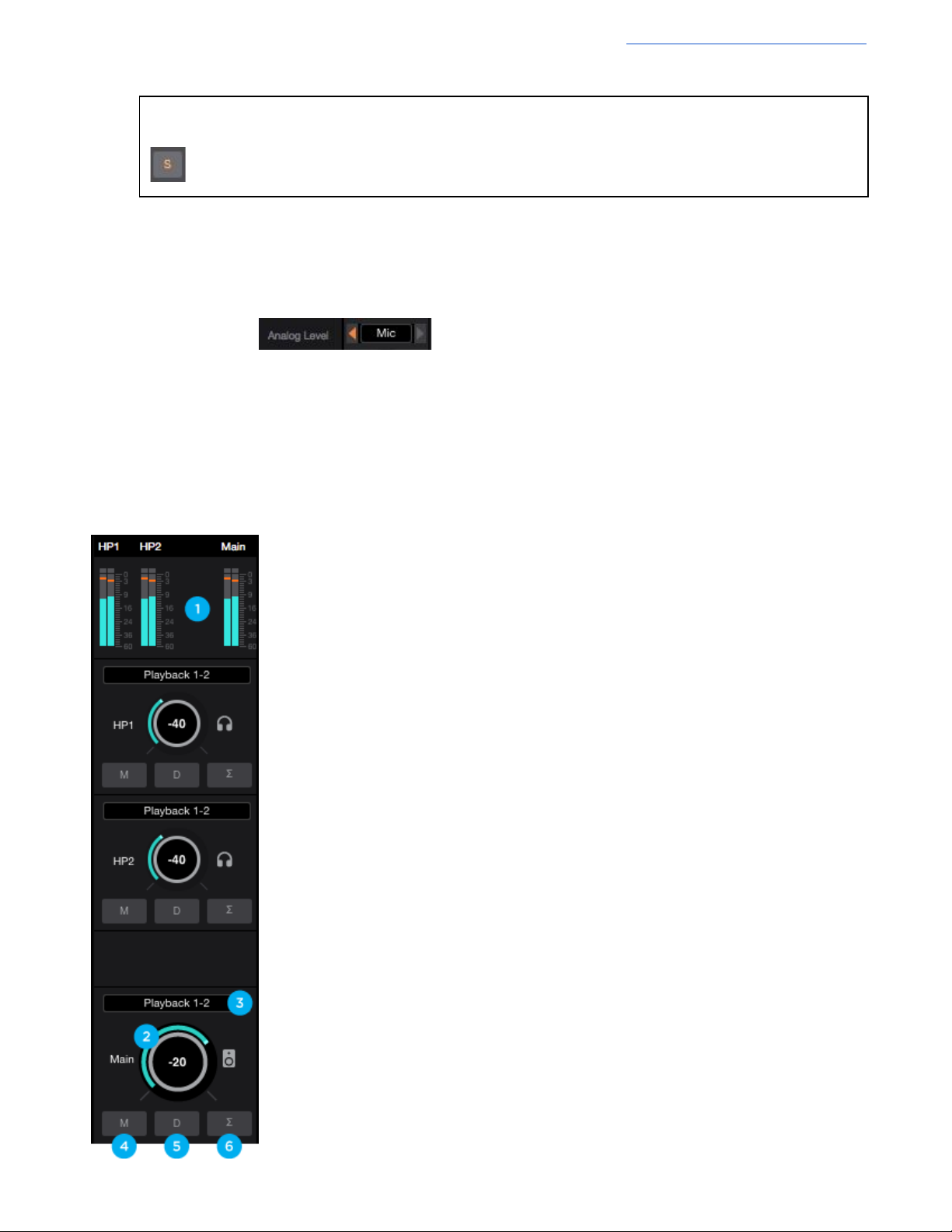
The Monitor/Output Section is where you select what you hear in the outputs, and control the volume of the various outputs.
The Output Level Meters are also a useful diagnostic tool to see if signal should be present at the various outputs.
1. Output Level Meters - Displayed the output level. Is not affected by the output level
control.
2. Output Level Control - Set the listening level of the Main or Headphone outputs.
3. Output Source Selector - Selects the sound source for each output. The options
are:
● Playback - Sends a playback channel stereo signal directly to this output,
bypassing all mixers.
● Mix or FX Send - Send the stereo signal from this mixer’s Master to this
output
4. Output Mute button - Mutes the output
5. Output Dim button - Reduces the output listening level by -15dB
6. Sum-To-Mono button - Collapse left and right signals to mono at the output. This
combined signal is sent through both Left and Right Outputs and is useful for
verifying the mono-compatibility of a stereo mix.
16
Page 17
Apogee Element Series User’s Guide
Remote Window
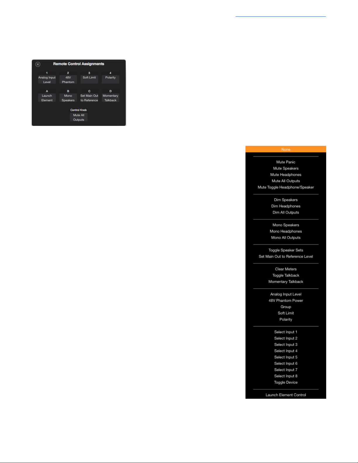
The Remote window provides settings to configure the optional Apogee Control hardware remote control. To open the Remote
window, choose Window > Remote, type Command+4 or click on the Remote toolbar button.
The nine buttons in the window - 1-4, A-D and Control Knob - are used to define the
function of corresponding hardware Function buttons.
The following functions are available for all buttons:
None - When a button is assigned to None, it does nothing.
Mute Panic - Mute the headphone and Speaker outputs of all connected units.
- Tapping the button again doesn’t un-mute the signal - it must be un-muted
in Element Control software.
Mute Speakers - Mute the Main speaker output (when two interfaces are connected,
Master interface only).
Mute Headphones - Mute the Headphone outputs of all connected interfaces.
Mute All Outputs - Mute the Speaker and all Headphone outputs; tap again to unmute.
Mute Toggle Headphone/Speaker - Toggle between two states:
1. All Headphone outputs muted and the Speaker output unmuted
2. All Headphone outputs unmuted and the Speaker output muted.
- When recording in the same room as speakers, this function provides one
button switching between recording with headphones and listening back
over speakers.
Dim Speakers - Lower the Speaker output by 15dB (when two interfaces are connected,
Master interface only).
Dim Headphones - Lower the Headphone outputs of all connected interfaces by 15dB
Dim All Outputs - Lower the Speaker and all headphone outputs by 15dB
Mono Speakers - Sum the stereo Speaker output to mono (when two interfaces are
connected, Master interface only).
Mono Headphones - Sum the Headphone outputs of all connected interfaces to mono.
Mono All Outputs - Dim the Speaker and all Headphone outputs.
Toggle Speaker Sets - (Element 88 only) Toggle playback between the A and B Speaker
Sets, when Main Output Format (Device sidebar) is set to 2 Speaker Sets.
Set Main Out to Reference Level - Set the Main output level to a predetermined
reference level, from -64 to 0 dB. To determine the reference level, use an
external audio measurement tool and set the Main Out control to generate
the desired SPL level. Once Main Out is set, then
Level”. Now, when that button is pushed, Main Out jumps to the saved level.
assign a Function button to “Set Main Out to Reference
17
Page 18
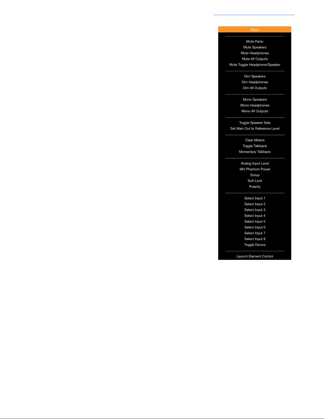
Clear Meters - Clear held peak and overs from Element Control software level meters.
Toggle Talkback - Turn the Talkback function on indefinitely until the button is tapped a
second time to turn it off.
Momentary Talkback - Turn the Talkback function on only when the button is held
down. Releasing the button turns Talkback off.
Analog Input Level - Toggle through an input’s Analog Level settings (+4 dBu, -10 dBV,
Mic, Instrument) when that input is selected for control. If the Headphone
or Speaker output is selected for control and a button assigned to Analog
Input Level is tapped, all LEDs flash for a moment to indicate an invalid
operation.
48V Phantom Power - Toggle 48V Phantom Power on/off for the input selected for
control
Group - Toggle Group on/off for the input selected for control
Soft Limit - Toggle Soft Limit on/off for the input selected for control
Polarity - Toggle Polarity Inversion on/off for the input selected for control
Select Input 1..8 - Select the designated input (1-8) for control. When two interfaces are
connected, use the Toggle Device setting to toggle between Interface A
1-8 and Interface B 1-8.
Toggle Device - Toggle the interface selected for control when two interfaces are
connected. By setting the 8 Function buttons to Select Input 1, Select
Input 2, etc and setting the Control Knob to Toggle Device, it’s possible to
access both interfaces’ mic pre gain setting with only a few button taps.
Launch Element Control - Launch Element Control software or, if software is already
launched, bring the app into keyboard focus.
Apogee Element Series User’s Guide
18
Page 19
Apogee Element Series User’s Guide
Hover Help Window
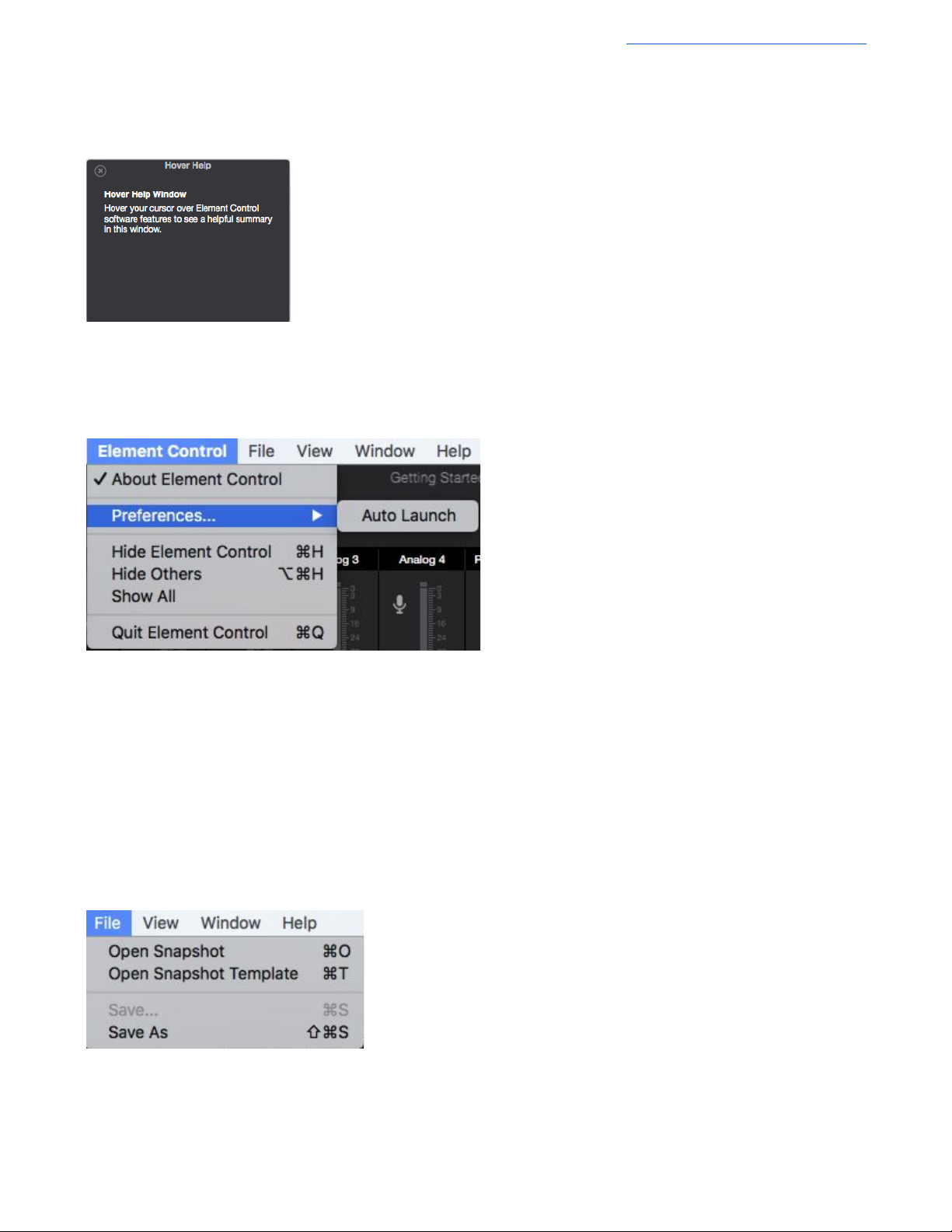
For specific information about Element Control’s features, open the Help window and hover your Mac’s pointer above each
setting to see a helpful summary.
Menu Bar Menus
Element Control Menu
About Element Control - Choose this menu item to display version information
for all hardware connected and software elements installed on your Mac.
Preferences > Auto Launch - Choose this menu item to launch Element Control
when an Element Thunderbolt interface is connected to the computer.
Hide Element Control - Choose this menu item to hide the Maestro application
Hide Others - Choose this menu item to hide all other open applications
Show All - If any open applications have been hidden, choose this menu
item to reveal all open applications
Quit Element Control - Choose this menu item to quit Element Control
File Menu
Open Snapshot - Choose this menu item to open a user-saved snapshot template file on your computer.
Open Snapshot Template - Choose this menu item to open the Snapshot Template Chooser window.
Save - Choose this menu item to save a user-customized Snapshot file to a location on your computer.
Save As - Choose this menu item to save a customized Snapshot file in a new name or new location on your computer.
19
Page 20
Apogee Element Series User’s Guide
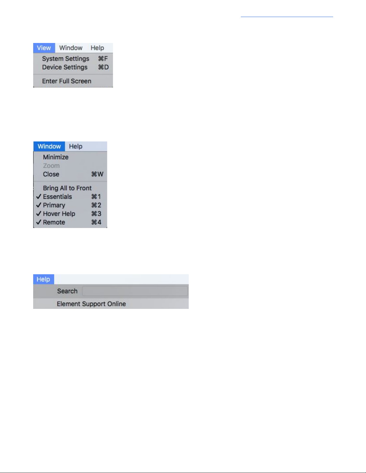
View Menu
System Settings - Choose this menu item to open the System Settings sidebar
Device Settings - Choose this menu item to open the Device Settings sidebar
Enter Full Screen - Choose this menu item to expand Element Control to fill the display screen.
Window Menu
Selecting an item in the Window Menu switches to a view of that selection.
Help Menu
Use the Search Field to search for a specific menu item.
Element Support Online - Select this menu item to be taken to the Apogee website’s Support page for Element.
20
Page 21
Apogee Element Series User’s Guide
iPhone
iPad
Apogee Control iOS App
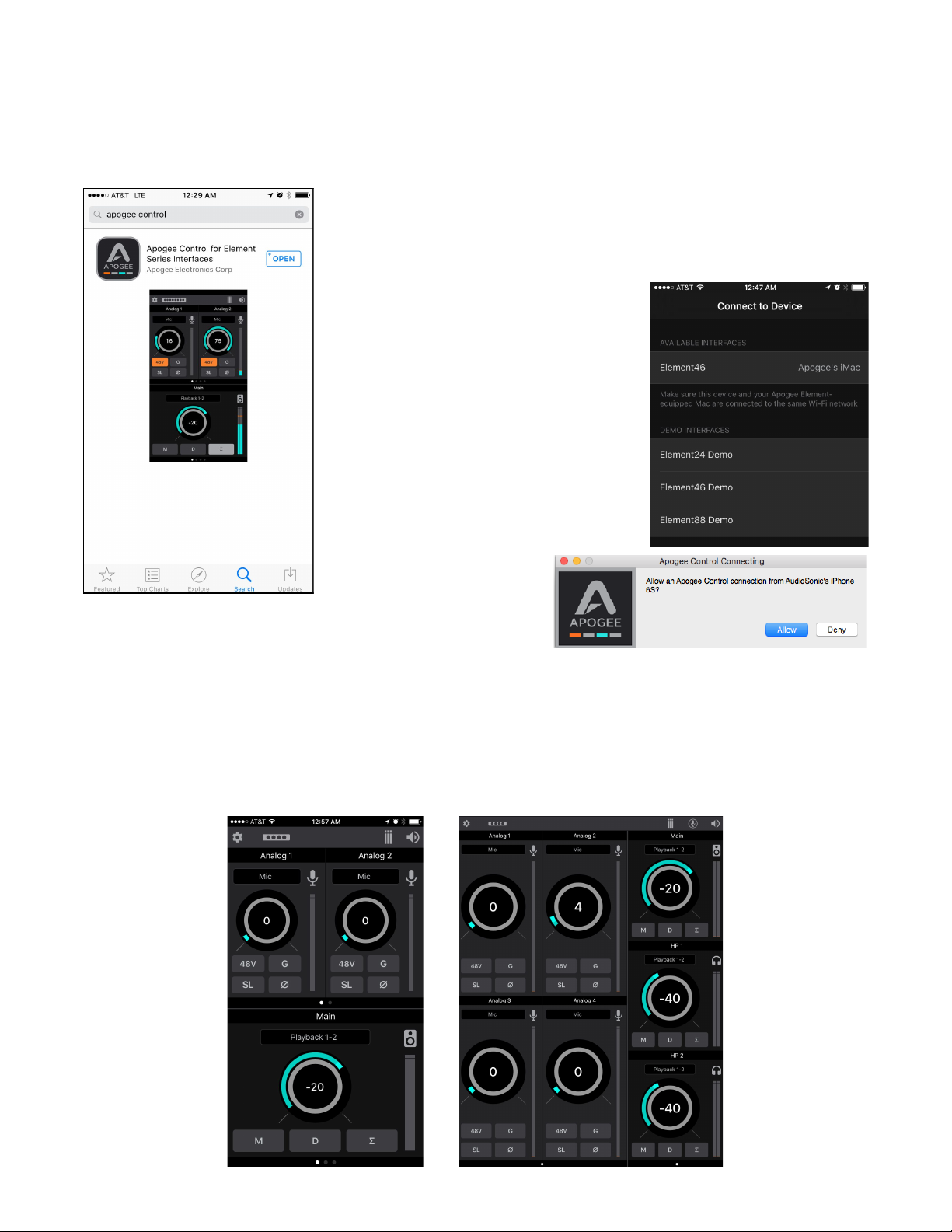
Many of the features and settings of the Apogee Element Thunderbolt interface can be controlled by the free Apogee Control
iOS app. Here’s how it works:
1. Open the App Store app on your iPad, iPhone, or iPod Touch and search for
Apogee Control.
2. Download and open the Apogee Control app and the “Connect to Device” screen
will appear.
3. Your Apogee Element interface will appear
in the “Available Interfaces” list if:
● Your iOS device & your Mac are
connected to the same WiFi network
● The Element Driver Software has been
installed on this Mac computer
● The Element Interface is powered on and
connected to your Mac computer
5. Select your Element Interface from the list of
Available Interfaces
6. A message will appear on your Mac: Click Allow.
7. The main Control screen will appear. It is separated into three sections:
● Toolbar
● Analog Input settings
● Monitor Output settings
21
Page 22
Apogee Element Series User’s Guide
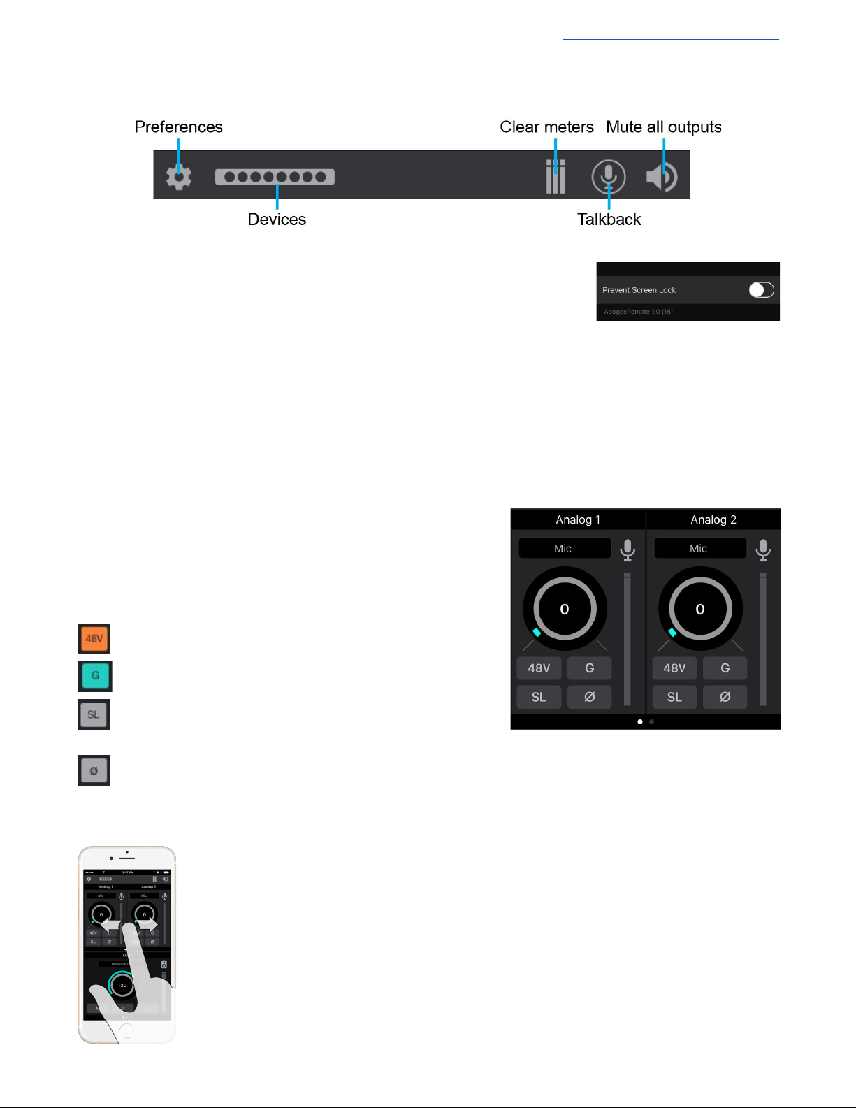
iOS App Toolbar
Preferences - Opens the Preferences Menu
Prevent Screen Lock - When engaged, the iOS device’s screen will not
automatically turn off while the Control app is open.
Devices - Opens the Connect to Device Menu.
Clear meters - Clears any Peak Hold or Over Hold indicators on the level meters.
Talkback - Tap and hold to engage Momentary Talkback; release to disengage Momentary Talkback;
Double-tap to toggle Talkback on; tap again to toggle Talkback off.
Mute all outputs - Engages Mute on all speaker and headphones outputs. These mutes must be manually disengaged.
Analog Input Settings
Provides options and controls related to the analog inputs of your Apogee Element Thunderbolt Interface
Input Source
- Mic - XLR input is sent through the microphone preamp
- Instrument - ¼” input is sent through a Hi-Z to Low-Z circuit then to the
microphone preamp
- +4dBu/-10dBV - Live level signal from XLR input bypasses preamp
circuit
Gain - Drag your finger up or down on the gain circle to adjust the Input Gain
48V - Toggles phantom power on/off
G - Group the input gain controls of adjacent odd-even channels
SL - Soft Limit attenuates transient peaks of the analog input at a
threshold of -4dBfs before the signal is sent to the A/D converter.
- Inverts the input signal’s polarity
Input Icon - The icon provides visual indication of the type of Input Source selected
Input Level Meter - Shows the input signal strength after going through the preamp circuit.
Navigation
- Use your finger to swipe left or right to page to additional analog inputs
22
Page 23
Apogee Element Series User’s Guide
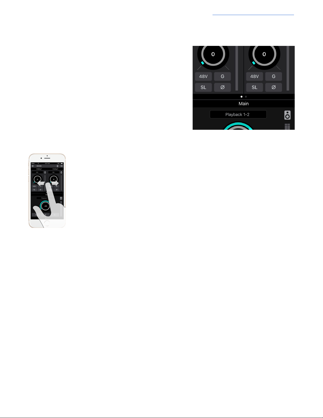
Monitor Output Settings
Provides option and controls related to the Main and Headphones outputs of your Apogee Element Thunderbolt interface.
Output Source Selector - Selects the sound source for this output. The
options are:
Playback - Sends a playback channel stereo signal directly to this
output, bypassing all mixers.
Mix or FX Send - Send the stereo signal from this mixer’s Master to
this output
Output Mute button - Mutes the output
Output Dim button - Reduces the output listening level by -15dB
Sum-To-Mono button - Collapse left and right signals to mono at the output.
This combined signal is sent through both Left and Right Outputs and is
useful for verifying the mono-compatibility of a stereo mix.
Output Level Meters - Displayed the output level. Is not affected by the output level control.
Output Level Control - Set the listening level of the hardware output.
Navigation
- Use your finger to swipe left or right to page to additional analog outputs
23
Page 24
Apogee Element Series User’s Guide
Snapshots & Examples
When Element Control software is first opened, you are presented with a Snapshot Template chooser.
The following section will explain and explore these default Snapshot Templates in depth, with use-cases demonstrating how
each would be used in with a recording program (DAW) like Logic Pro X.
24
Page 25
Apogee Element Series User’s Guide
Getting Started Snapshot Template
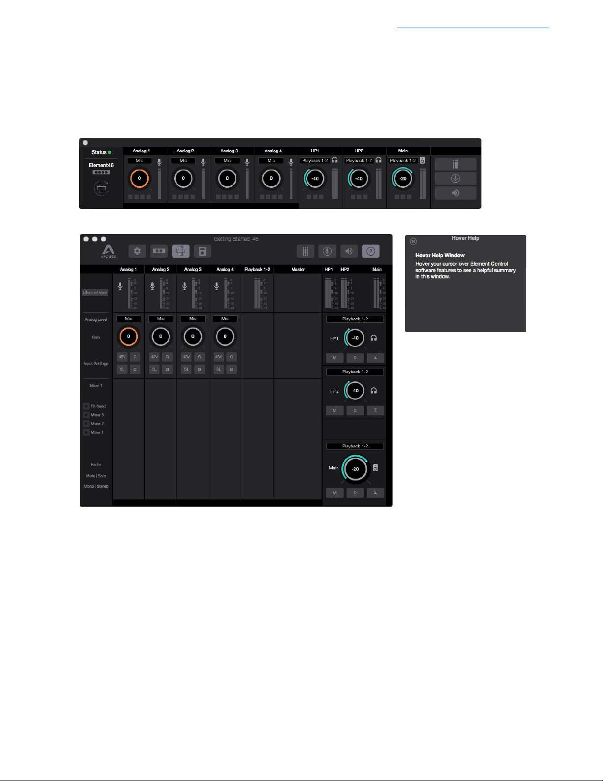
This Snapshot Template provides simple input settings in the Input Channel section, a single stereo playback channel for
audio playing from audio software such as iTunes or your DAW, and output settings for dealing with your speaker and
headphone outputs. This represents the most common and familiar use of an audio interface.
This template provides:
Primary Window -
● All Analog Input Channels - Provides settings for adjusting & controlling the analog inputs as well as input level
meters to show the strength of incoming signal.
● One Playback Channel - For audio signal being played from an audio application on your Mac.
● No Mixer Section - Mixers are hidden in this Snapshot. Use of the Mixers will be explained later in this guide.
● Monitor Section - Provides settings & controls for headphones and speaker outputs. You can choose the sound
source for each output allowing some sounds to come through some outputs and other sounds to come out of other
outputs.
Essentials Window - Provides the same settings and controls as the Analog Input Channels and Monitor Section.
Hover Help - Hover your Mac’s pointer above each setting of Element Control software to see a helpful summary.
Each of these sections dictate how and where audio signal flows between the Element Thunderbolt Interface’s hardware
connections and the recording software (DAW) tracks and channels on your computer. Lets analyze that signal flow:
25
Page 26
Apogee Element Series User’s Guide
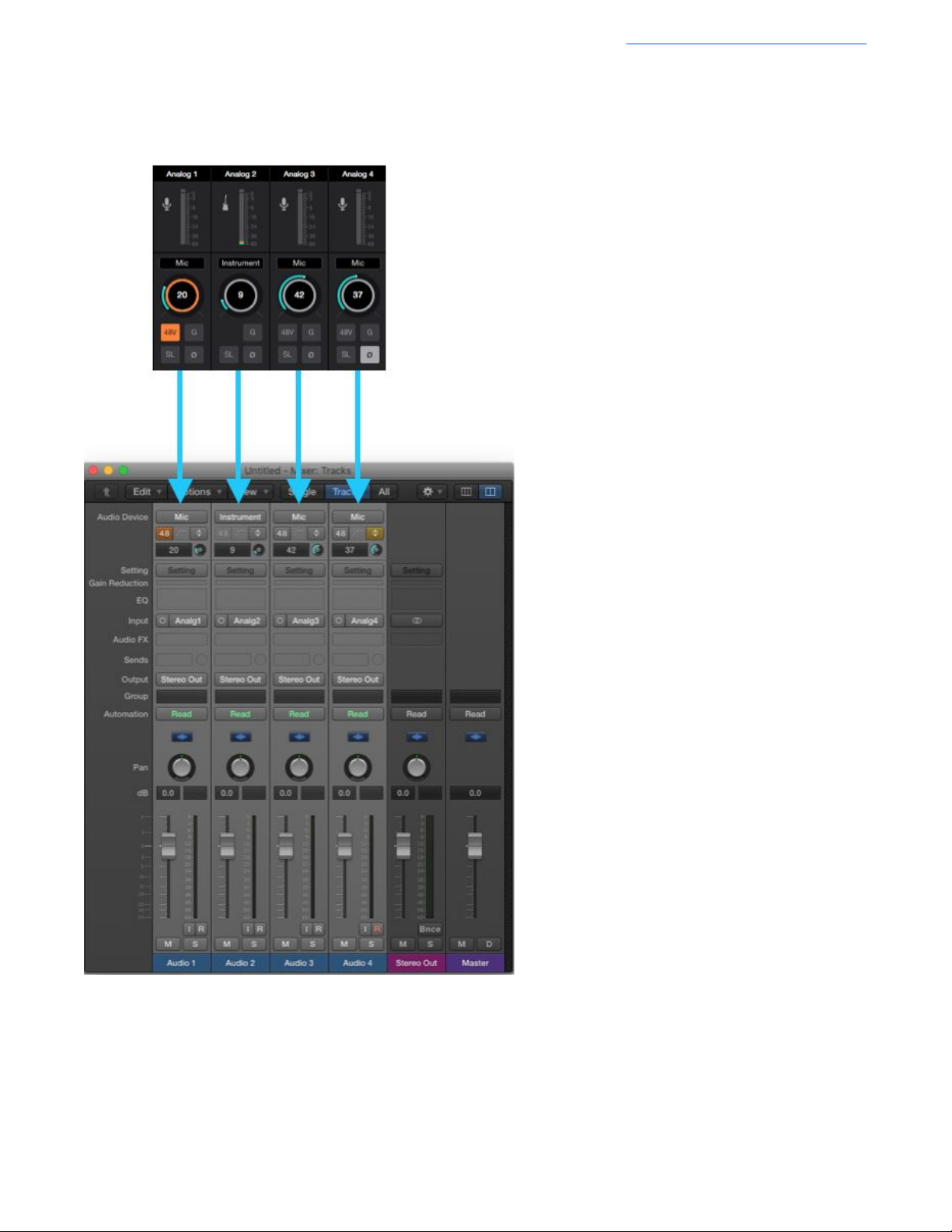
How Element Control Input Channels appear in your Recording Program:
The Analog Input Channels of Element Control allow
you to select the type of input you are using: Mic,
Instrument, or Line Level +4dBu/-10dBV.
You may activate phantom power (48V) for condenser
mics, Group (G) channels together in stereo pairs, turn
on Soft-Limit (SL), or invert the polarity (⌀) of any of
these input channels.
In your recording program, any audio track you create
can be set to record these Analog Inputs.
In this example Logic Pro X project, four audio tracks
have been created with each track set to Input 1, 2, 3,
and 4 respectively. In this way, each Element 46
interface audio Input Channel corresponds with the
four tracks created in Logic Pro X.
You can think of your audio signal as flowing from the
analog inputs of your Element interface, through the
Element Control software’s Analog Input Channels,
then into the Logic software.
Note: With the Audio Device control feature in Logic
Pro, you can see that the settings made on these Input
Channels in Element Control are matched/mirrored by
the Audio Device section of the Logic Pro X mixer
The audio signal then flows through these Logic tracks
until it eventually exits through the Logic Output
channels.
From there the signal flows back into the Element
Control software:
.
26
Page 27

Apogee Element Series User’s Guide
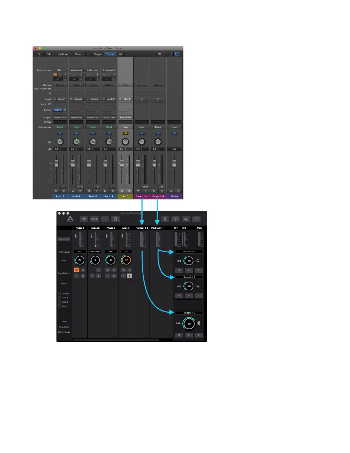
How Element Control Outputs work with your Recording Program:
Signal from the Stereo Output of Logic
Pro X appears in Element Control’s
Playback 1-2 channel.
This Playback 1-2 signal will flow to the
Element interface’s outputs because the
audio source for the Headphone and
Main speaker outputs is set to Playback
1-2.
In this way, the same signal is played
from all of the Element Thunderbolt
analog audio outputs.
27
Page 28
Apogee Element Series User’s Guide
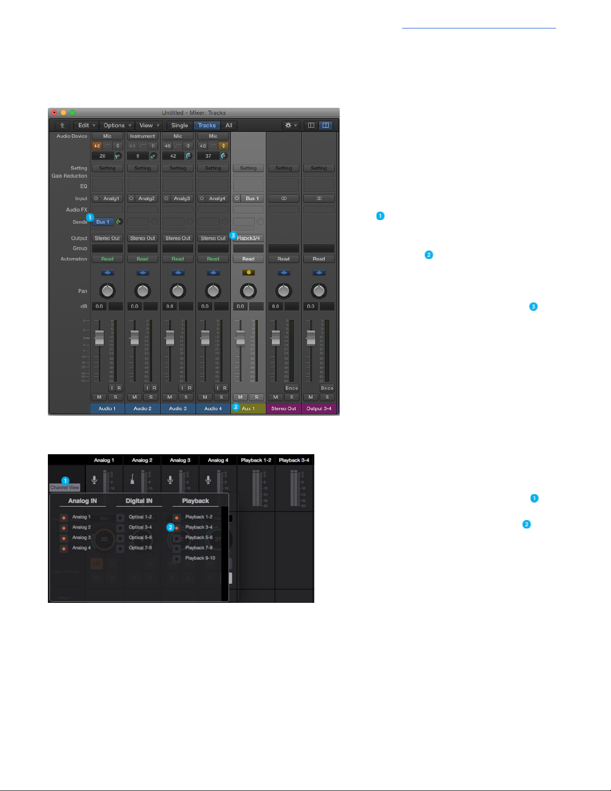
How to get a separate mix to the headphones than from the speaker outputs:
To do this, you first have to create an aux mix in your Recording Program.
In Logic, create a Send to a Bus on one of your
tracks
This automatically creates an Aux track in your
Logic Pro X Mixer
- In Pro Tools and other DAW’s you must
manually create an Aux Track
Set this Aux track to output via Playback 3-4 .
Next, go to Element Control and click Channel View .
Click Playback 3-4 to show that playback channel .
28
Page 29
Apogee Element Series User’s Guide
Set the Headphones output to Playback 3-4
to send this signal to your headphones
output.
The Main monitor outputs are still set to
Playback 1-2 and play audio from Logic’s
Stereo Out master track.
29
Page 30
Apogee Element Series User’s Guide
Essentials Snapshot Template
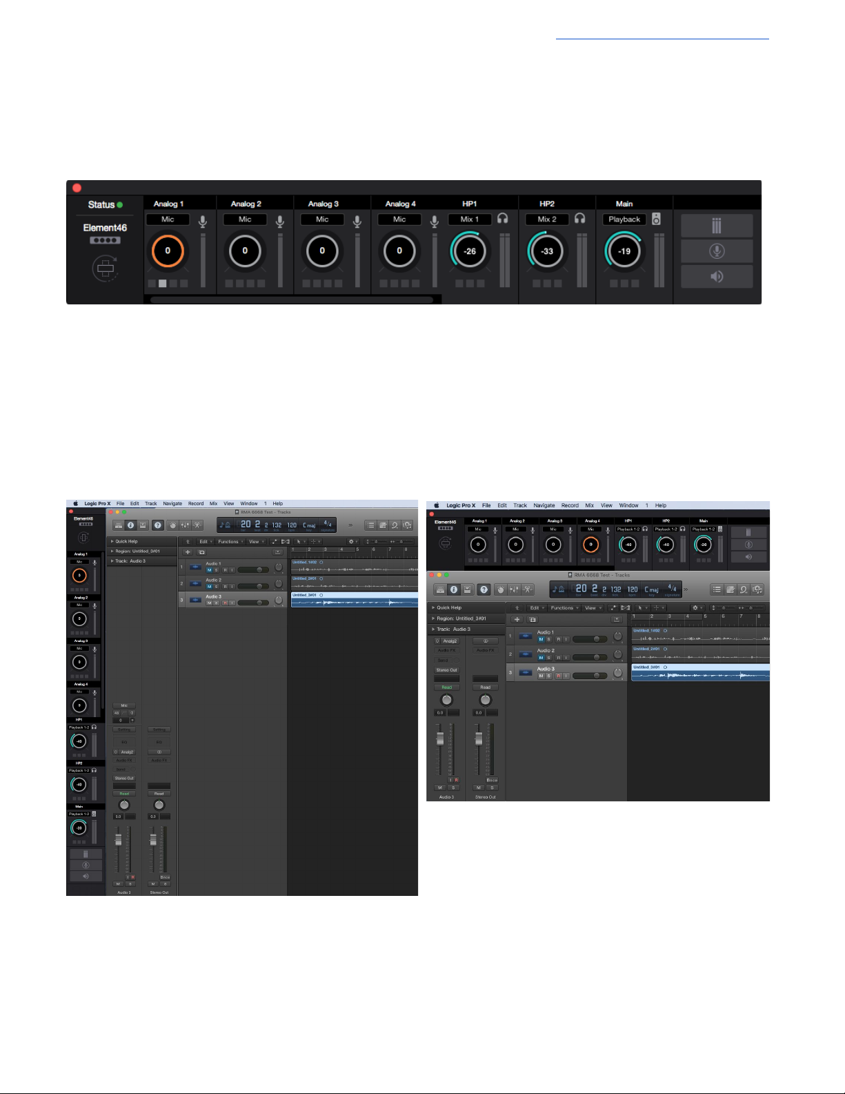
This Snapshot Template is the same as the Getting Started Snapshot Template but only the Essentials Window is displayed.
This represents the simplest layout of the Element Control software. It provides controls for only Inputs and Outputs. All other
settings are disabled or hidden:
All Analog Input Channels and Monitor output controls are represented in the Essentials bar. The small buttons below the Gain
controls correspond to the Input Settings 48V, G, SL, and ⌀. The buttons under the Output Volume controls correspond to the
output buttons M, D and Σ.
For convenience, the Essentials bar can be converted to a vertical orientation via the Orientation Button. In this way, the
Essentials bar can be placed next to your DAW software for easy access.
30
Page 31

Apogee Element Series User’s Guide
Direct Monitoring Snapshot Template
This Snapshot Template is perfect for users who do not want to open a DAW in order to listen to their inputs. It does this by
setting the headphones and speaker outputs to “Mix 1”. In this way, any channel that has the Mixer 1 fader raised will be
heard. This snapshot is also for users who want the lowest latency monitoring possible, and can’t achieve a low enough buffer
in their DAW for software monitoring to be acceptable.
This template provides:
● All Analog Input Channels - Provides settings for adjusting & controlling the analog inputs as well as input level
meters to show the strength of incoming signal.
● One Playback Channel - For audio signal being played from an audio application on your Mac.
● Mixer 1 Showing - Mixer 1 is the key to direct monitoring and is used to send signal from the various input channels
directly to the Monitor Section.
● Monitor Section - All the main and headphone outputs are set to Mix 1.
31
Page 32
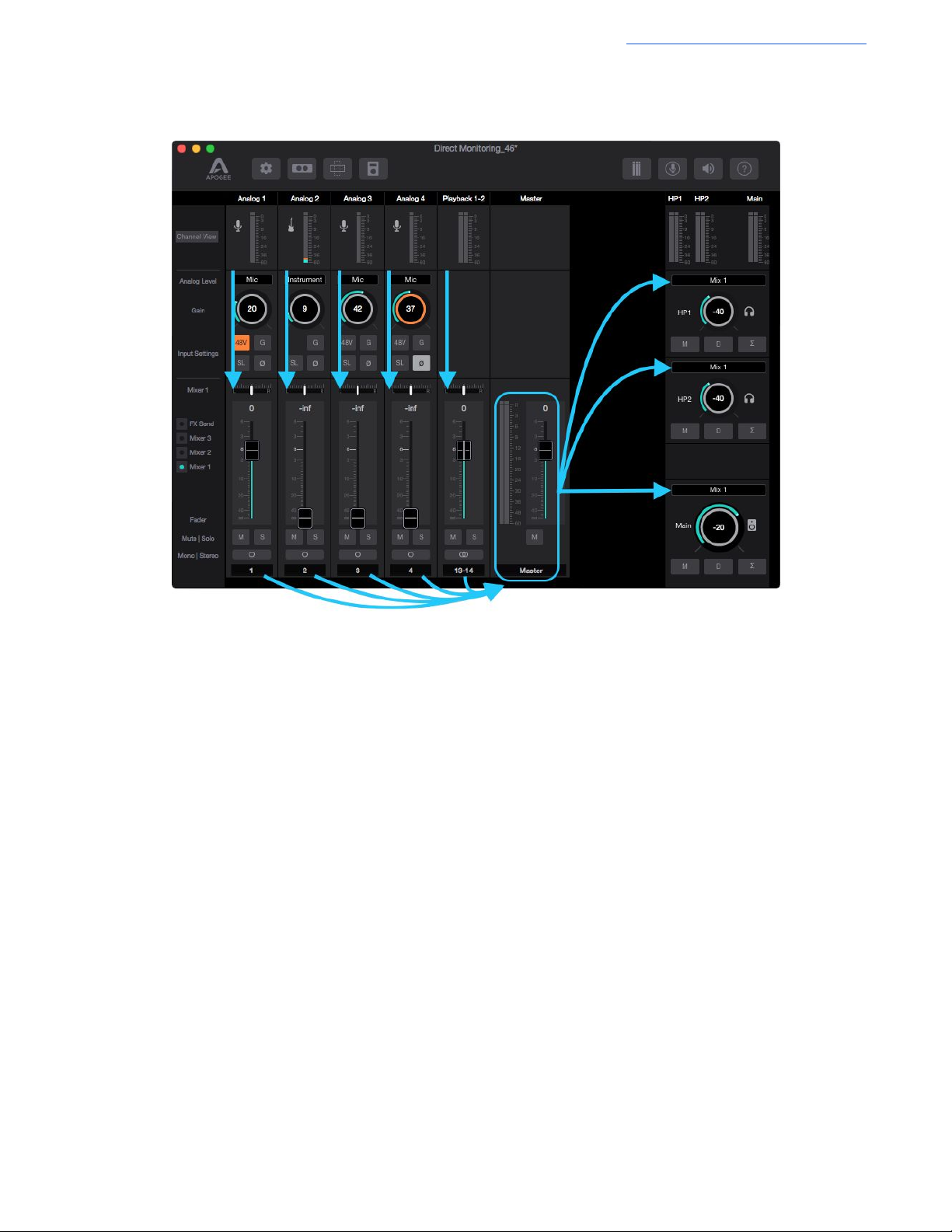
Let’s analyze the signal flow:
Apogee Element Series User’s Guide
Any signal from the Input Channel Section must go through the Mixer 1 fader before it will be heard in the outputs that are set
to “Mix 1”. This has a few benefits:
● An analog or digital input can be heard directly through the interface rather than having to setup an audio track with
software monitoring in a recording program first.
● Provides a very low-latency monitoring path.
● Direct input signals can be mixed with audio from Playback channels such as your recording program or iTunes or
YouTube, etc.
Note that signal from the Input Channels go to your recording software (DAW) at the same time they are being sent to the
Mixer 1. In this way, this Direct Monitoring Snapshot can be used with a DAW that is unable to achieve a low enough buffer
size to get the latency delay to be acceptable. Here’s how you would set up this Snapshot Template with a recording program
like Logic:
32
Page 33
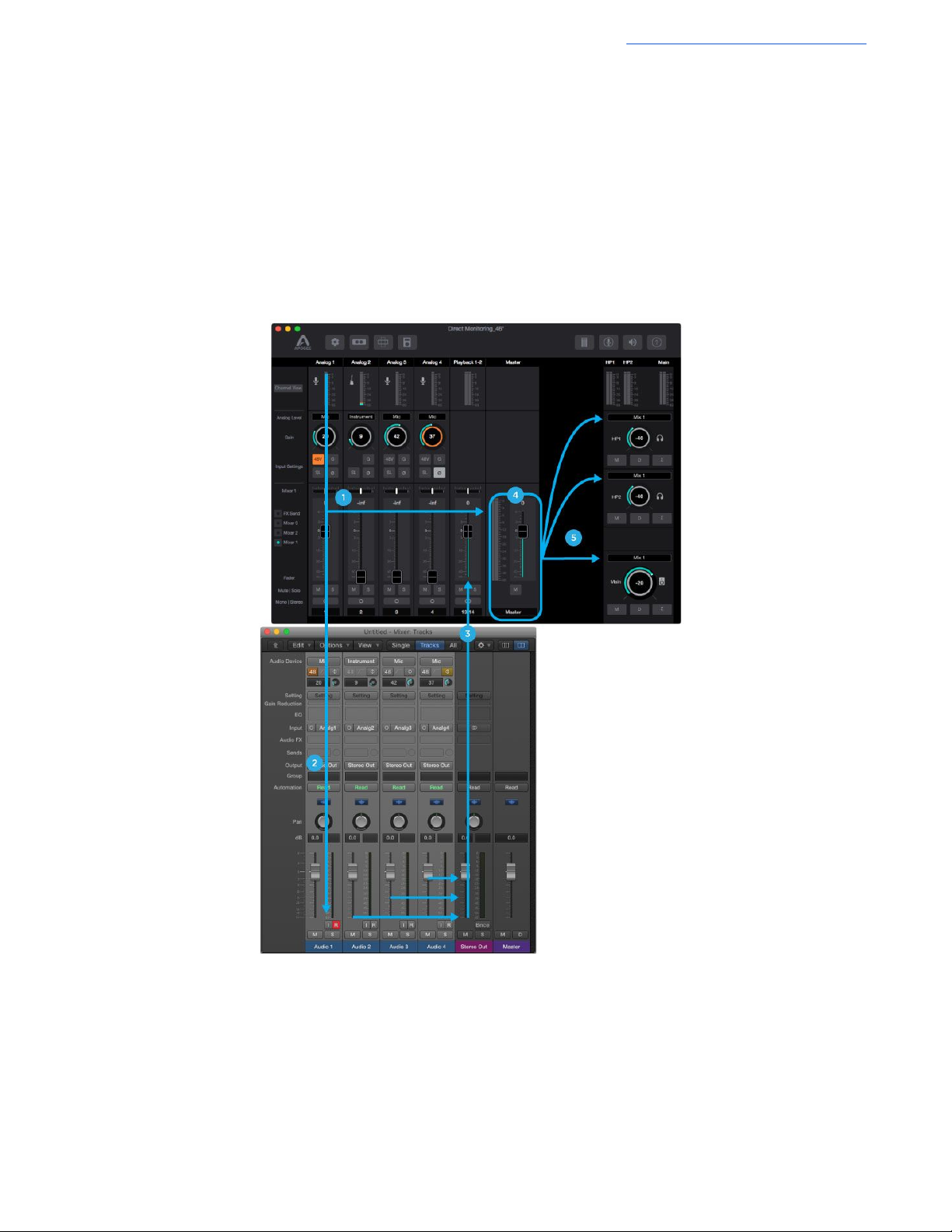
Apogee Element Series User’s Guide
Using the Direct Monitor Snapshot Template with your Recording Program
1. Setup an audio track in Logic.
- Make sure input monitoring on that track is turned off because you are direct monitoring through Element
Control instead.
2. Record to that track.
3. Setup a second audio track in Logic that also has input monitoring turned off.
4. Record the second track. You will be able to hear the first track as you record.
5. Adjust the Mixer 1 channel faders to control the volume of direct input you are recording vs playback of already
existing recording playing back from Logic.
The signal flow would look like this:
1. Input signal from Analog 1 is sent to both Logic and the Mixer 1
2. In Logic, the signal is routed to an Audio track for recording. Input Monitoring on this track is off.
3. Playback from Logic is sent to Element Control’s Playback 1-2 Input Channel.
4. Both the direct signal from Analog 1 Input channel, and Playback 1-2 Input Channel are mixed together to the Mixer 1
Master.
5. Mixer 1 feeds the Main and Headphones outputs.
This same Snapshot Template can be used in other recording programs like Pro Tools, Cubase, Ableton Live, etc. by using
the same principles shown in this example.
33
Page 34
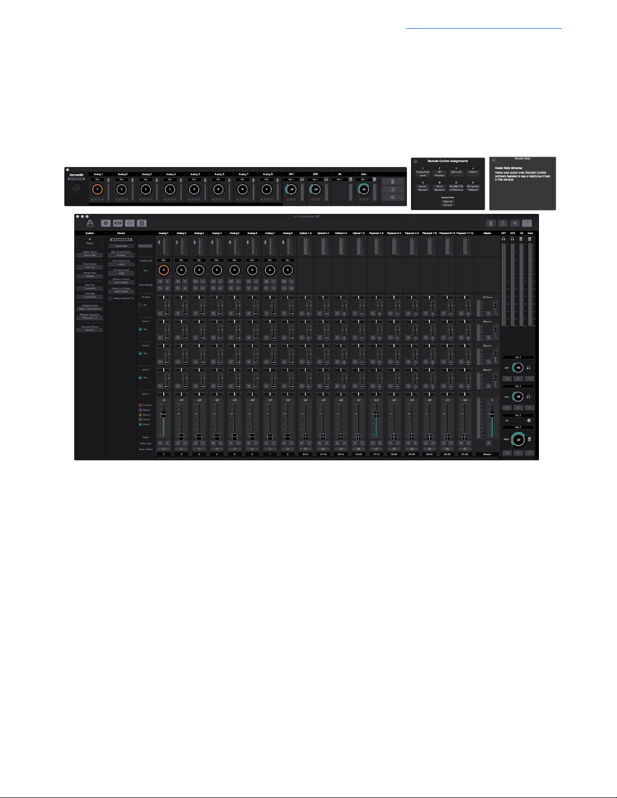
Apogee Element Series User’s Guide
Full Functionality Snapshot Template
For the user that wants a “god-view”, this Snapshot Template has all side-panels, mixers, and channels visible.
Note: All outputs are set to “Mix 1” in this Snapshot like the Direct Monitoring Snapshot Template. Therefore you must raise
the Mixer 1 channel faders to hear anything in the outputs.
34
Page 35
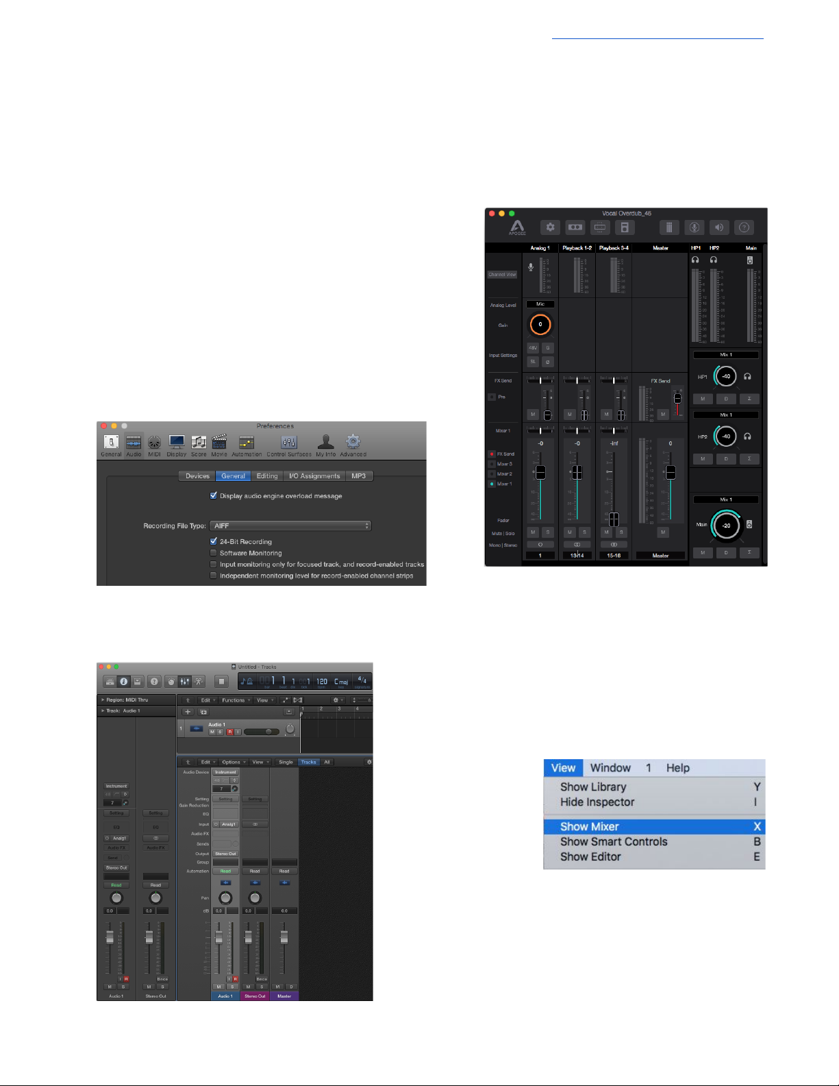
Apogee Element Series User’s Guide
2. Create an Audio track. Set the input to Analog 1.
Note: For the purposes of this guide, having the
Mixer visible will make things easier. To do this:
● Go to the View Menu > Show Mixer.
Vocal Overdub Snapshot Template
This Snapshot Template is conceived for an overdubbing recording session. At this stage in the recording process, a recording
project is typically full of tracks and plugins which may require your I/O Buffer to be set to a large size. Because software input
monitoring with such a large buffer would result in too much latency, this snapshot is designed for Direct Monitoring a single
input, but using Element Control’s FX Send to apply your DAW’s reverb to the Low Latency (Direct Monitoring) mixer inputs.
Notice that in this Snapshot Template:
- The Mixer 1 and FX Send are both displayed
- The Outputs are set to “Mix 1” for direct monitoring
- There is a single analog input channel active, and two playback
input channels active.
Here’s how this is set up using Logic Pro X:
1. In Logic Pro X > Preferences > Audio > General, uncheck the
boxes for “Software Monitoring” and “Input monitoring only for
focused track, and record-enabled tracks”
35
Page 36
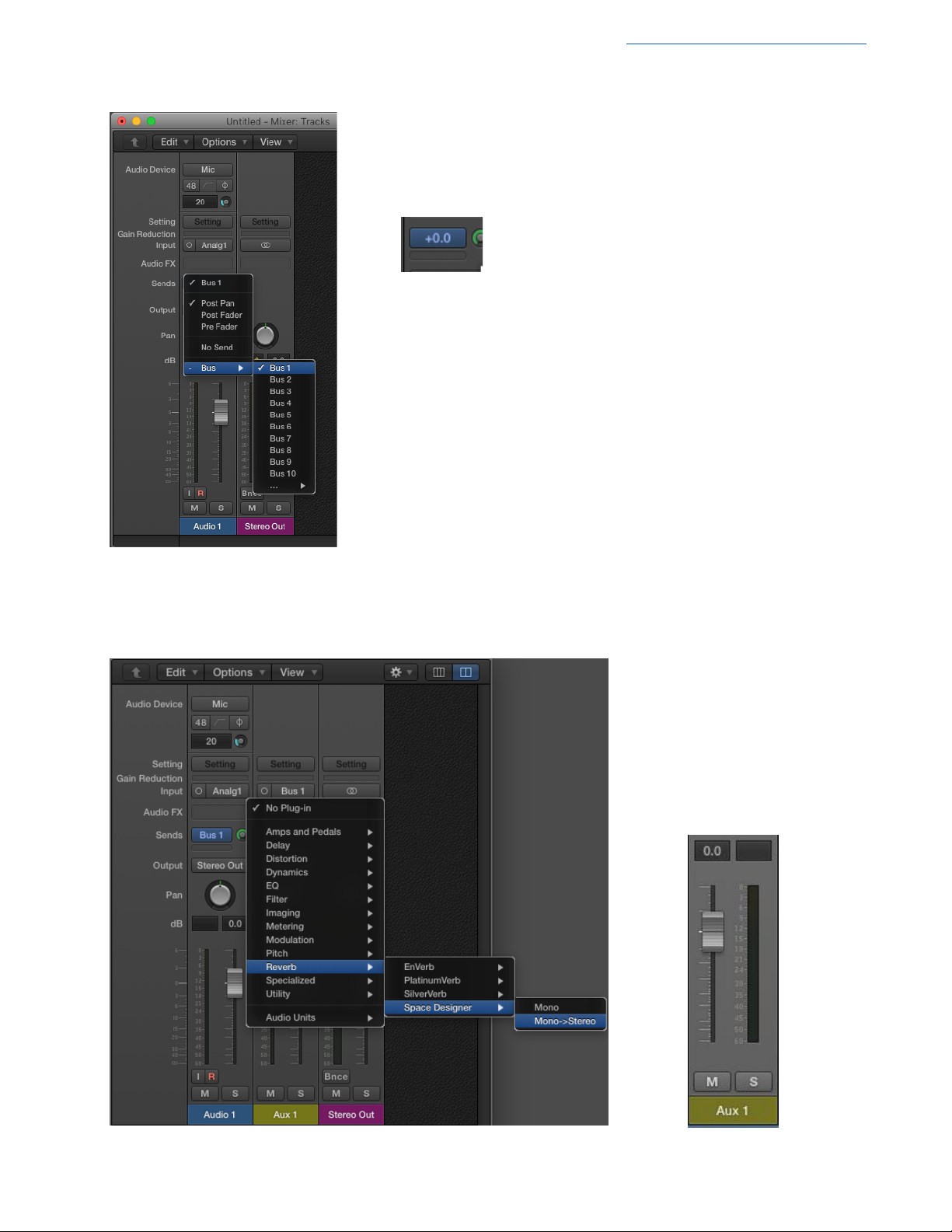
Setup a standard reverb send and return for this audio track:
3. In the “Sends” section of the Audio track, create a Bus send.
Set the Bus level to 0.0dB.
When you create the Bus send, Logic will automatically create an Aux track with
that bus selected as the input.
Note: You will need to manually create the Aux track in other DAW’s like
Pro Tools, Cubase, Live, etc.
4. In the new Aux input track, instantiate your favorite reverb plugin.
Apogee Element Series User’s Guide
Raise the Aux 1 channel fader to
0.0dB.
36
Page 37
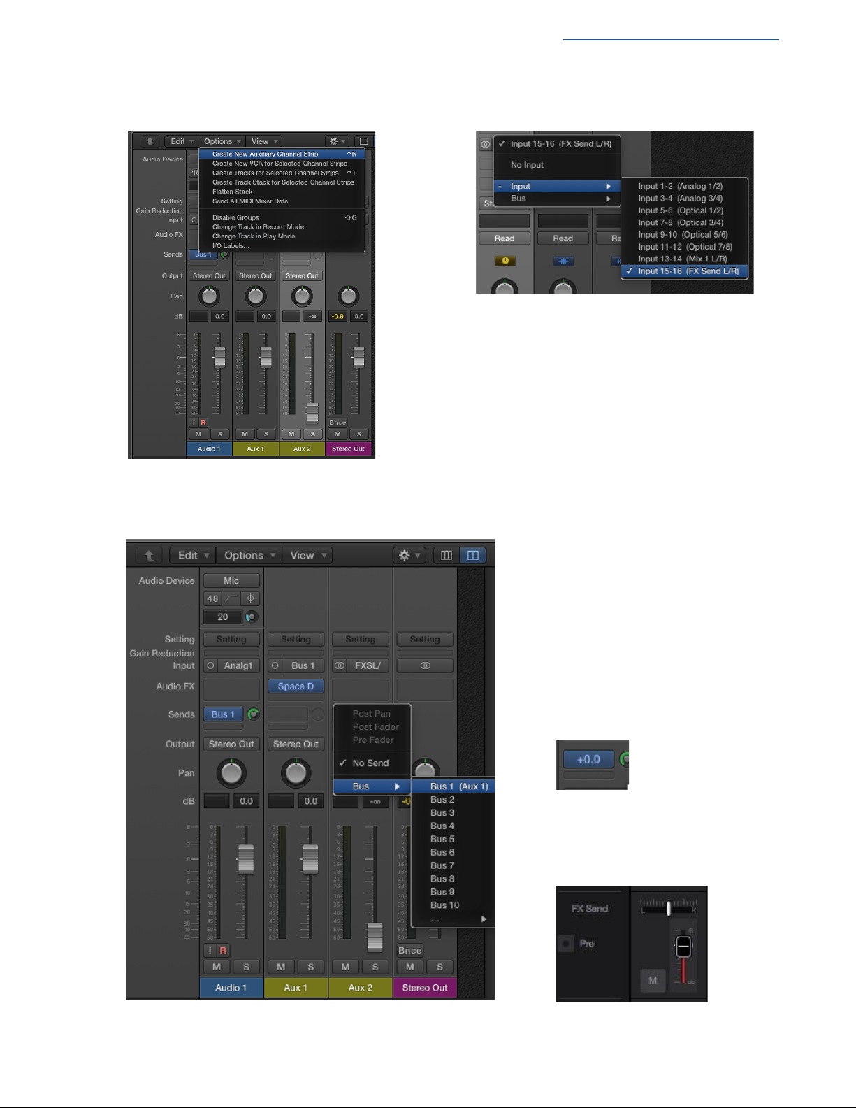
5. In the mixer view’s Option’s menu, create a New
Auxiliary Channel Strip.
6. Set this new Aux 2 channel’s input to the FX Send
L/R (Input 15-16 in this example)
Apogee Element Series User’s Guide
7. Set the Aux 2 channel to “No Output” (or lower the fader), and create a bus send to the same
bus as the Audio track.
Set the Bus level to 0.0dB.
10. In Element Control, raise the FX Send
fader for the Analog 1 channel to 0.0dB
37
Page 38
Apogee Element Series User’s Guide
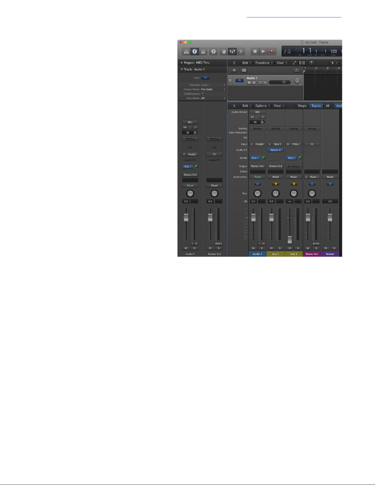
At the end, your Logic Project will look like this:
This creates a dual-path signal flow:
● Path 1 happens when Recording
● Path 2 happens when Playing back that
recording
Path 1:
Audio from Element Control Analog 1 input is sent to
Logic’s Audio 1 track for recording.
This Analog 1 Input signal also goes via the FX Send to
Logic Aux 2 input, which then Bus sends to the Aux with
the Reverb plugin.
The Reverb Aux output is routed to the stereo output of
the Logic session which returns to the Element Control
mixer via Playback 1-2.
Element Control Mixer 1 combines the Analog 1 signal
with the reverb from Playback 1-2 and the mix of these
is sent to the Main and Headphone outputs.
Path 2:
When playing back the recording in Logic’s Audio track 1, the Bus 1 Send on this track sends the signal to the Aux with the
Reverb Plugin applied.
This Audio playback track and Reverb Aux track is mixed in Logic’s Mixer and sent to the Stereo Out, where it arrives in
Element Control via Playback 1-2.
Element Control Mixer 1 then sends the Playback 1-2 signal on to the Main and Headphone outputs.
For both Path 1 & 2:
● Since the bus send level to the Reverb plugin in Logic is the same for recording and playback, the reverb sound
doesn’t change from recording to playback.
● Adjust the Bus 1 sends for a proper level to the Reverb Aux track, then adjust the Reverb Aux track fader until the
desired amount of reverb is heard.
38
Page 39
Apogee Element Series User’s Guide
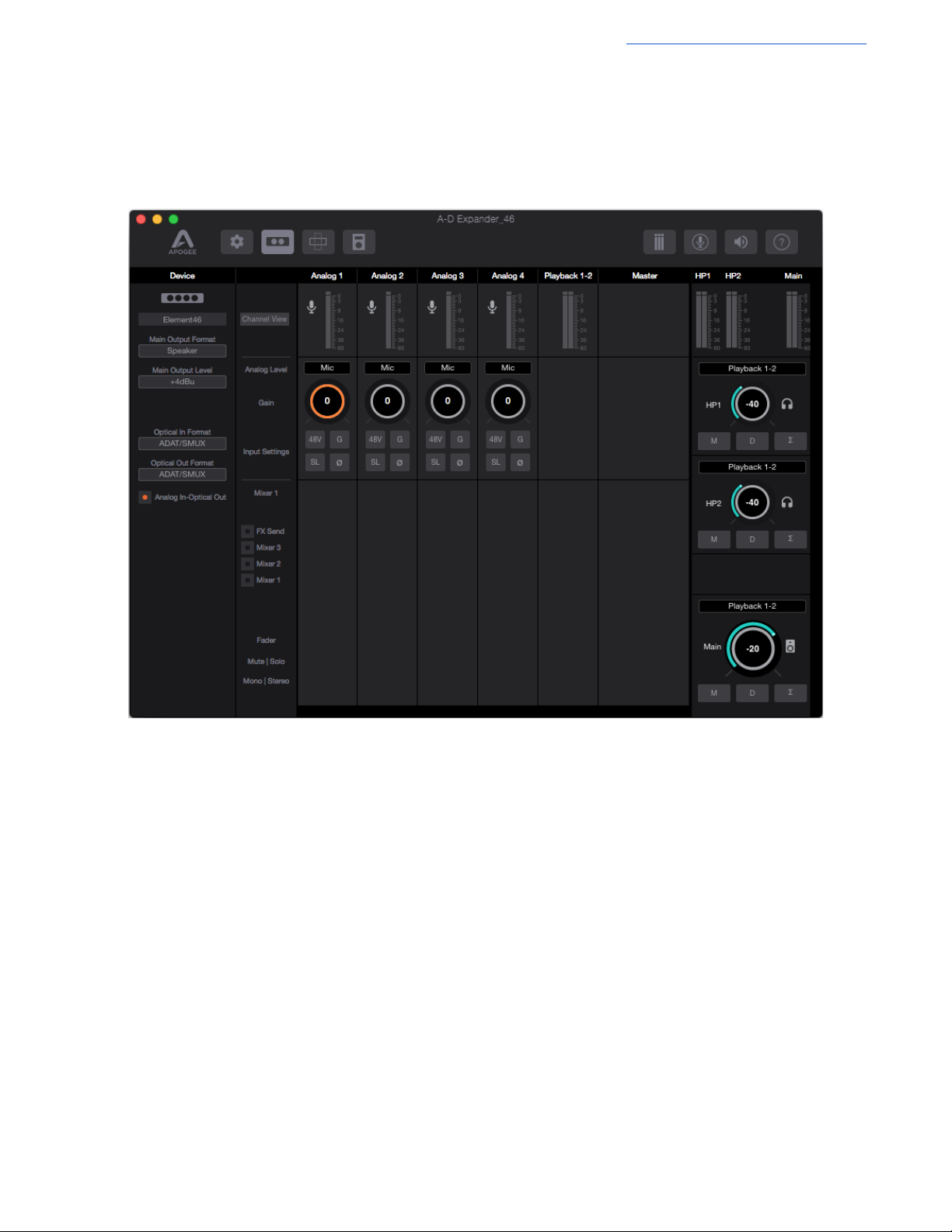
A/D Expander Snapshot Template
This Snapshot Template facilitates the use of your Element Firewire interface as a simple Analog to Digital Converter (A/D).
This snapshot is useful when wanting to send digital audio to a Digital Mixer, or separate Audio Interface. In this way, you can
utilize the excellent Apogee Preamps and Converters through another digital audio system.
The Individual Analog inputs are sent directly to the ADAT optical outputs.
● Element 24 - Analog input 1 - 2 > ADAT output ch 1 - 2
● Element 46 - Analog input 1 - 4 > ADAT output ch 1 - 4
● Element 88 - Analog input 1 - 8 > ADAT output ch 1 - 8
39
Page 40
Apogee Element Series User’s Guide
Working with a Multiple Element Interface Setup
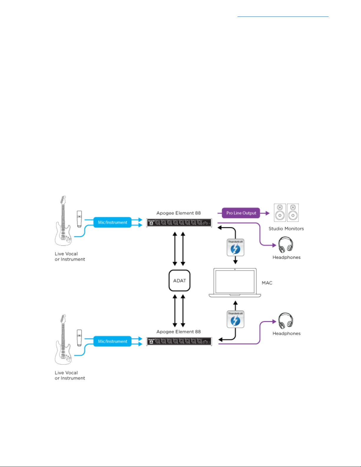
The connection of any two Element Series interfaces is supported in any desired order, for a system with up to 16 analog
inputs, 8 line outputs, and 4 headphone outputs.
Connecting a Multiple Element Interface System:
To connect multiple Element interfaces:
● A Mac with at least two Thunderbolt ports is required
● Element interfaces may be connected directly to your Mac or after dual-port Thunderbolt peripherals
● The Optical I/O of both interfaces is used for digital clocking and audio signal bussing between the interface’s low
latency (direct) monitoring mixers. Thus, Optical I/O is not available for external connections in a Multiple Element
Interface System
40
Page 41
Apogee Element Series User’s Guide
The Multiple Element Interface System in Use
When a Multiple Element Interface System is first powered up, one of the two interfaces is designated at random to be the
Master interface. The Master’s front panel LED light will be green while the Slave’s front panel LED light will be blue (if the
Slave interface LED is flashing red, check that optical cables are connected as shown above).
Note that only the Master interface has these attributes:
● System clock master
● Main outputs configurable for connection to speakers
● Inputs listed first in DAW input lists.
To change the Master device, open the System sidebar, then change the designated interface in the Master Device dropdown.
Inputs and outputs of the two Element interfaces are aggregated in the Apogee Thunderbolt driver, so that both interfaces
appear as one audio device named Apogee Thunderbolt in your DAW or in OS X System Sound Preferences. To distinguish
inputs for each interface, Master input labels include the prefix A, Slave input labels include the prefix B.
Likewise, Element Control Input settings, Low Latency mixer channels, and Main/Headphone output controls are labelled with
A and B prefixes to distinguish Master and Slave software controls.
Once two Element interfaces have been connected, Element Control retains data from both, even if one of the interfaces is
later disconnected. This means that even if one interface is missing, the I/O detected by your DAW and OS X remains
consistent, plus all previously saved Snapshots remain compatible.
Disconnected interfaces appear as “offline” devices; all settings in Element Control pertaining to an offline device appear in a
greyed out state.
To permanently delete an offline device, open the Device sidebar and click on the Trashcan icon at the
bottom of the offline device’s settings.
41
Page 42

Additional Support
For more information
● Apogee KnowledgeBase and FAQs
● Informational Videos
● Apogee Product Registration
● How to contact Apogee Technical Support
Please visit:
www.apogeedigital.com/support
Apogee Element Series User’s Guide
42
Page 43
Specifications
Mac OS:
● Computer: Thunderbolt™ equipped Mac (iMac,
Mac Mini, Macbook, Macbook Pro, Macbook Air,
Mac Pro)
● Memory: 4GB RAM minimum, 8GB recommended
● OS: 10.10 or greater
● Connection: Any available Thunderbolt™ port*
● Power: DC Power supply included
*Thunderbolt cable not included
Compatible Software:
● Any Mac Core Audio Compatible application
● Recommended apps: Logic Pro, Pro Tools, Ableton
Live, Garageband, MainStage, Final Cut Pro, Digital
Performer, Studio One, Cubase and Nuendo
Preamps, Inputs, and Outputs
Mic Preamps
Gain: Up to 75 dB and advanced stepped gain circuit design
Selectable 48v phantom power, hi-pass filter, Soft Limit and polarity invert
EIN: 129dB (un-weighted) @ 60dB, 150 Ohm input
Max input level: +20dBu
Input impedance: 3K Ohm
A/D Conversion:
Max input level (+4dBu ref/Mic): +20dBu
Max input level (-10dBV ref): +6dBV
Input impedance: 5KOhm
Freq resp 10 Hz -20Khz: > +/-0.2dB (@44.1Khz)
Rel. THD + N: -110dB
Dyn. Range: 119dB (A-weighted)
D/A Conversion:
Max output level (+4dBu ref): +20dBu
Max output level (-10dBV ref): +6dBV
Line output impedance: 90 Ohm
Freq resp 10Hz -20 Khz: > +/- 0.05dB (@44.1Khz)
Rel. THD+N : -114dB
Dyn Range: 123dB (A-weighted)
Headphone Max output level:
● 560mW into 30 Ohm
● 90mW into 600 Ohm
Headphone THD+N: -107 dB with 600 Ohm load @ 19 dBu
Headphone Dyn Range: 117dB a-weighted
Weights and Dimensions
Element 24
9.75” x 5.5” X 1.75″
24.5cm x 14cm X 4.5cm
2.5lbs
1.14kg
Element 46
11.5” x 5.5” x 1.75″
29.5cm x 14cm x 4.5cm
2.95lbs
1.34kg
Element 88
13.5” x 5.5” X 1.75”
35cm x 14cm X 4.5cm
3.5lbs
1.6kg
System Requirements
Apogee Element Series User’s Guide
43
Page 44

Apogee Element Series User’s Guide
Warranty Information and Legal Notices
APOGEE ELECTRONICS CORPORATION warrants this product to be free of defects in material and manufacture under
normal use for a period of 12 months. The term of this warranty begins on the date of sale to the purchaser from an authorized
Apogee dealer (proof of purchase in the form of a receipt may be required). Units returned for warranty repair to Apogee or an
authorized Apogee warranty repair facility will be repaired or replaced with a functional equivalent product that is new or
refurbished at the manufacturer’s option, free of charge. Please note this guarantee may be subject to other conditions as
dictated by the customer’s legal warranty rights under the applicable national legislation governing the sale of consumer
goods.
Apogee reserves the right to change or improve design at any time without prior notification. Design changes are not
implemented retroactively, and the incorporation of design changes into future units does not imply the availability of an
upgrade to existing units. This warranty is void if Apogee determines, in its sole business judgment, the defect to be the result
of abuse, neglect, alteration or attempted repair by unauthorized personnel. The buyer acknowledges and agrees that in no
event shall the company be held liable for any special, indirect, incidental or consequential damages, or for injury, loss or
damage sustained by any person or property, that may result from this product failing to operate correctly at any time.
Warranty details are subject to change. For the latest warranty information please visit www.apogeedigital.com.
Declarations of Conformity
This device complies with Part 15 of the FCC Rules. Operation is subject to the following two conditions:
(1) This device may not cause harmful interference and (2) This device must accept any
interference received, including interference that may cause undesired operation. This
equipment has been tested and found to comply with the limits of a Class B digital device, pursuant to Part 15 of the FCC
Rules.
CAUTION: Changes or modifications not expressly approved by Apogee Electronics
Corporation compliance could void the user’s authority to operate the equipment.
Rating: 5V 400mA USB 2.0
Industry Canada Notice
This Class B digital apparatus meets all requirements of the Canadian
Interference-Causing Equipment Regulations. Cet appareil numérique de la classe B respecte toutes les exigences du
Règlement sur le matérial brouilleur du Canada.
Declaration of Conformity – CE
Apogee Electronics Corporation hereby declares that the products, Element 24, Element 46, Element 88 and Apogee Control,
to which this declaration relates, are in material conformity with the following standards or other normative documents:
(EN50081-1/EN55022; 1995) and (EN50082-1/IEC 801-2, 3, 4; 1992)
following the provisions of: (73/23/EEC – Low Voltage Directive)and (89/336/EEC – EMC Directive)
Declaration of Conformity – CE
Apogee Electronics Corporation hereby declares that the products, Element 24, Element 46, Element 88 and Apogee Control,
to which this declaration relates, are in material conformity with the following standards or other
normative documents:
44
Page 45

Apogee Element Series User’s Guide
(EN50081-1/EN55022; 1995) and (EN50082-1/IEC 801-2, 3, 4; 1992)
following the provisions of: (73/23/EEC – Low Voltage Directive)
and (89/336/EEC – EMC Directive)
Declaration of Conformity – Japan Apogee Electronics Corporation hereby declares that Element 24, Element 46, Element 88
and Apogee Control, to which this declaration relates, are in material conformity with the VCCI Class A standard.
Declaration of Conformity – Australia
Apogee Electronics Corporation hereby declares that Element 24, Element 46, Element 88 and Apogee Control are in material
conformity with AN/NZS standard requirements.
45
 Loading...