

Page 1

AAPP88AADD && AAPP88DDAA
24-bit, 8-channel 96kHz-ready
A/D & D/A Converter Cards
for Yamaha digital systems equipped with
YGDAI and Mini-Y expansion slots
Installation Guide
v1.1 — May 2000
Page 2

PACKAGE CONTENTS
• Apogee YDGAI A/D or D/A card with “full size” YGDAI faceplate
• “Mini-Y” faceplate
• This Owner’s Manual
Cables are not included and are available separately.
Manual written by Julio Alvarez
Edited by Richard Elen, Roger Robindoré and Joe Raia.
Interconnection diagrams by Julio Alvarez.
Produced, edited and generally mangled for production by Richard Elen.
Technology within the Apogee YDGAI cards, including the Low Jitter Clock, may be covered by one or more
patents that are the property of Apogee Electronics Corporation.
Registered User Customer Support:
For customer support, please call (310) 915-1000 and ask for Tech Support,
or email
support@apogeedigital.com.
Technical Support is available to registered owners, via telephone, email or on the Web. As soon as you can,
please send in your registration card – or register on-line at http://www.apogeedigital.com/ > support > on-line
registration.
Features and specifications subject to change without notice.
© 2000 APOGEE ELECTRONICS CORPORATION
3145 Donald Douglas Loop South
Santa Monica,
California 90405-3210 USA
Tel: +1 310/915-1000
Fax: +1 310/391-6262
Email:
info@apogeedigital.com
Web: http://www.apogeedigital.com/
This manual is copyright ©2000 by APOGEE ELECTRONICS CORPORATION. All rights reserved. Under copyright laws, this manual may not be duplicated in whole or in part without the written consent of Apogee.
AP8AD & AP8DA Card Installation Guide
Page 2
Page 3
AP8AD & AP8DA Card Installation Guide
Page 3
Warnings
WARNING: To reduce the risk of fire or electrical shock, do not expose this appliance to rain or moisture.
This symbol, wherever it appears, alerts you to the presence of uninsulated dangerous voltage inside
the enclosure—voltage that may be sufficient to constitute a risk of shock. Operations indicated with
this symbol should be carried out only by technically-qualified personnel.
This symbol, wherever it appears, alerts you to important operating and maintenance instructions in
the accompanying literature. Read the manual.
Please read the following before installing and operating the Apogee AP8AD and AP8DA Cards.
Warnings
• Do not locate the Apogee YGDAI A/D and D/A cards in a place subject to excessive heat or in direct sunlight. This could damage the cards.
• Do not place the cards in a place subject to excessive humidity or dust. This could damage the cards and
present fire and electrical shock hazards when installed.
• Do not try to modify the cards in any way. This could potentially damage the cards, cause safety hazards,
and will void the warranty.
• When not installed, always keep the cards in the anti-static bag they came in.
Cautions
• When installing the cards, make sure that the device into which the card is being installed is powered down.
Also make sure that the slots are free of debris and foreign objects.
• When powering on the device, if you notice any abnormality – such as smoke, odor, or noise – turn off the
device into which the card is installed immediately. Remove the power cord from the AC outlet. Confirm
that the abnormality is no longer present. Consult your dealer for repair.
• Do not use any chemicals to clean the cards.
• Never touch the card’s printed circuit board – hold the card by its edges.
• When installing the cards, make sure that you are properly grounded to avoid electrostatic discharge that
could damage the components.
FCC warning
This equipment has been tested and found to comply with the limits for a Class A digital device, pursuant to Part 15 of the FCC rules. These limits are designed to provide reasonable protection against
harmful interference when operated in a commercial environment. This equipment generates, uses,
and can radiate radio frequency energy and, if not installed and used in accordance with the instruction manual, may cause harmful interference to radio communications. Operation of this equipment in a residential area
is likely to cause harmful interference, in which case the user will be required to take whatever measures may
be required to correct the interference at their own expense.
Copyright Notice
The Apogee AP8AD and AP8DA are computer-based devices, and as such contain and uses software in
ROMs. This software, and all related documentation, including this Owner’s Manual, contain proprietary infor-
mation which is protected by copyright laws. All rights are reserved. No part of the software and its related documentation may be copied, transferred, or modified. You may not modify, adapt, translate, lease, distribute,
resell for profit or create derivative works based on the software and its related documentation or any part
thereof without prior written consent from Apogee Electronics Corporation, U.S.A.
Page 4

Registration and Warranty Information
Be sure to register your AP8AD or AP8DA, either by filling in the enclosed Registration Card
or by completing the on-line registration form at our Web site:
http://www.apogeedigital.com/. If you do so, Apogee can contact you with any update infor-
mation. As enhancements and upgrades are developed, you will be contacted at the registration
address. Firmware updates are free for the first year of ownership unless otherwise stated.
Please address any inquiries to your dealer or directly to Apogee at:
APOGEE ELECTRONICS CORPORATION, 3145 Donald Douglas Loop South, Santa Monica, CA 90405, USA.
TEL: (310) 915-1000, FAX: (310) 391-6262
email: support@apogeedigital.com. Web: http://www.apogeedigital.com/
APOGEE ELECTRONICS CORPORATION warrants this product to be free of defects in material and manufacture under normal use for a period of 12 months. The term of this warranty begins on the date of sale to the
purchaser. Units returned for warranty repair to Apogee or an authorized Apogee warranty repair facility will be
repaired or replaced at the manufacturer’s option, free of charge. All units returned to Apogee or an autho-
rized Apogee repair facility must be prepaid, insured and properly packaged. Apogee reserves the right to
change or improve design at any time without prior notice. Design changes are not implemented retroactively,
and the incorporation of design changes into future units does not imply the availability of an upgrade to existing units.
This warranty is void if Apogee determines, in its sole business judgment, the defect to be the result of abuse,
neglect, alteration or attempted repair by unauthorized personnel.
The warranties set forth above are in lieu of all other warranties, expressed or implied, and Apogee specifically disclaims any and all implied warranty of merchantability or of fitness for a particular purpose. The buyer
acknowledges and agrees that in no event shall the company be held liable for any special, indirect, incidental
or consequential damages, or for injury, loss or damage sustained by any person or property, that may result
from this product failing to operate correctly at any time.
USA: Some states do not allow for the exclusion or limitation of implied warranties or liability for incidental or
consequential damage, so the above exclusion may not apply to you. This warranty gives you specific legal
rights, and you may have other rights which vary from state to state.
Service Information
If the AP8AD or AP8DA is kept in a clean environment free of excess dust, moisture and heat, it will give years
of trouble-free service.
The AP8AD or AP8DA contains no user-serviceable components: refer to qualified service personnel for repair
or upgrade. Your warranty will be voided if you tamper with the components on the card(s). If you have any
questions with regard to the above, please contact Apogee.
In the event your AP8AD or AP8DA needs to be upgraded or repaired, it is necessary to contact Apogee prior
to shipping, and a Return Materials Authorization (RMA) number will be assigned. This number will serve as a
reference for you and helps facilitate and expedite the return process.
Apogee requires that shipments be pre-
paid and insured
— unless otherwise authorized in advance. IMPORTANT: Any shipment that is not pre-paid
or is sent without an RMA number will not be accepted.
KEEP THIS MANUAL FOR FUTURE REFERENCE. PLEASE REFER TO IT BEFORE CALLING TECHNICAL SUPPORT. THE SUPPORT TECHNICIAN WILL HAVE YOU REFER TO IT DURING TROUBLESHOOTING.
AP8AD & AP8DA Card Installation Guide
Page 4
Page 5

Declarations of Conformity
Declaration of Conformity—FCC
Apogee AP8AD and AP8DA
These devices comply with Part 15 of the FCC Rules. Operation is subject to the following two conditions:
(1) These devices may not cause harmful interference, and
(2) These devices must accept any interference received, including interference that may cause undesired operation.
These devices have been tested and found to comply with the limits of a Class B digital device, pursuant to Part
15 of the FCC Rules. These limits are designed to provide reasonable protection against harmful inteference in
a residential installation. These devices generate, use and can radiate radio frequency energy and, if not
installed and used in accordance with the instructions, may cause harmful interference to radio communications.
If these devices do cause harmful interference to radio or television reception, which can be determined by turning the equipment off and on, the user is encouraged to try to correct the interference by one or more of the
following measures:
1. Re-orient or relocate the receiving antenna.
2. Increase the separation between the equipment and receiver.
3. Connect the equipment into an outlet on a different circuit from that to which the receiver is connected.
4. Consult the dealer or an experienced radio/TV technician for help.
NOTE: The use of non-shielded cable with this equipment is prohibited.
CAUTION: Changes or modifications not expressly approved by the manufacturer responsible for compliance
could void the user’s authority to operate the equipment.
Apogee Electronics Corporation, 3145 Donald Douglas Loop South, Santa Monica, CA 90405.
Betty Bennett, CEO.
Industry Canada Notice
This Class B digital apparatus meets all requirements of the Canadian Interference-Causing Equipment
Regulations.
Cet appareil numérique de la classe B respecte toutes les exigences du Règlement sur le matérial brouilleur
du Canada.
Declaration of Conformity – CE
Apogee Electronics Corporation hereby declares that the products, the AP8AD and AP8DA, to which this declaration relates, are in material conformity with the following standards or other normative documents:
• EN50081-1/EN55022; 1995
• EN50082-1/IEC 801-2, 3, 4; 1992
following the provisions of:
• 73/23/EEC – Low Voltage Directive
• 89/336/EEC – EMC Directive
Declaration of Conformity – Japan
Apogee Electronics Corporation hereby declares that the AP8AD and AP8DA,, to which this declaration
relates, are in material conformity with the VCCI Class A standard.
Declaration of Conformity – Australia
Apogee Electronics Corporation hereby declares that the AP8AD and AP8DA, are in material conformity with
AN/NZS standard requirements.
AP8AD & AP8DA Card Installation Guide
Page 5
Page 6

AP8AD & AP8DA Card Installation Guide
Page 6
Owner’s Record
The serial number is located on the rear panel of the unit. We suggest you record the serial number in the space
provided below. Refer to it whenever you call an authorized Apogee Electronics repair facility or the manufacturer. Please be sure to return your completed warranty card immediately!
Type: AP8AD AP8DA Serial No. ________________ Purchase Date __________________
Factory Firmware Revision ________________
Dealer____________________________________________________
Phone ____________________________________________________
Address ___________________________________________________
About This Guide
This manual was written to help you to install the AP8AD and AP8DA cards successfully. Due to the extensive
number of Yamaha products with YGDAI or Mini-Y expansion slots, we cannot cover the use of the cards in different Yamaha systems. To use the cards, refer to your Yamaha system manual for information on how to access
expansion cards and route signals to and from them.
This manual was also written to prevent damage to the cards during installation. Should you run into a problem when installing the AP8AD or AP8DA, the solution is hopefully contained in the following pages. We expect
that this manual will serve as the basis of your diagnosis of problems encountered and hope it will be used as
such prior to any calls to technical support at Apogee.
Remember — before calling technical support at Apogee, you must register this product either by sending
in the registration card or by registering on the Apogee Web site (http://www.apogeedigital.com). The technical support specialist will refer to the manual during your call and will expect that you have read it and understand the product to some degree.
If you have any suggestions on how to improve this Guide, please forward them to support@apogeedigital.com or fax them to +1-310-391-6262.
User’s Installation Notes
Space left blank for user tracking of factory modifications, option installations, software upgrades, manual revisions/ addenda, internal settings.
Page 7

AP8AD & AP8DA Card Installation Guide
Page 7
Unpacking and Installation
Please use care when unpacking the cards from the anti-static bag. Hold the card by the edges or the back
panel. Never touch the printed circuit board. When the card is not installed, always keep it in its anti-static bag.
Before installing the A/D card, please check the compatibility note at the end of this manual. Note: in the
Yamaha 02R, only slots 3 and 4 may be used for input cards such as the AP8AD A/D.
The Apogee YGDAI A/D and D/A cards come ready from the factory to be installed into the Yamaha 02R
and other Yamaha systems which require the wider, longer YGDAI card type. To install the card into the 02R or
another system with full-length YGDAI slots, simply:
1. Make sure the unit into which the cards will be installed is powered off and the AC power socket is switched
off. You may wish to keep the AC power cord connected to ground the unit. Remove the blanking panel
covering the slot you wish to use. Put the four mounting screws aside for use in step 4 below.
2. Make sure that you are grounded to earth to avoid damage to the cards by electrostatic discharge. For
example, touch the metal casing of the unit before opening the card’s anti-static bag.
3. Holding the card’s front panel, line up the edge of the card with the rails of the appropriate 02R slot. The
edge connector should face towards the inside of the console leaving the front panel with its 25-pin D-connector outside (flush with the back panel of the console). The 25-pin connector is used to connect analog
inputs and outputs.
4. Slide the card into the slot until it mates with the connector inside the slot, and insert the four mounting
screws to retain the card.
5. Connect a 25-pin D-sub to XLR loom to the 25-pin connector on the card. Make sure that the loom is wired
according to the pin configuration below. Note that this pin configuration is the same as is used by Tascam
for their DA-88 and similar recorders. A cable can be obtained from your Apogee dealer for this purpose,
or from your local Tascam dealer. Be sure to specify whether you require the cable for the AP8AD A/D card
(Analog IN) or the AP8DA D/A card (Analog OUT).
To insert the Apogee YGDAI A/D and D/A cards into products that require the smaller, “Mini-Y” card size
(e.g., D24 MO recorder, 01V and PM1D consoles, etc), do the following:
1. Examine the card carefully, noting the following characteristics. The card consists of two parts, the converter
card itself and an extender card which has an edge connector on each end
(see front cover illustration). The
two parts are held together by stabilizer strips that run the length of each edge of the card. These strips
are attached to the card by perforated tabs which enable them to be snapped off.
Pin-out for TASCAM DB25 8 Channel Balanced Connector
1 2 3 4 5 6 7 8
GCHGCH G
10111213
C H
G C H G C H G C H G C H G C H
987654321
141516171819202122232425
H = HOT
C = COLD
G = GROUND
Page 8

2. Carefully remove the stabilizing strips from each side of the card, by flexing them up and down until they
detach or by applying a sharp knife to the perforations.
3. After the strips have been removed, pull the converter card and the extender card apart. Discard the extender card section.
4. Remove the two nuts that attach the large format front panel to the converter card. Use the nuts to attach
the other, smaller front panel supplied in the card packaging. Insure that the 25-pin D-connector fits through
the hole in the front panel and insert the screws.
5. Make sure the unit into which the cards will be installed is powered off and the AC power socket is switched
off. You may wish to keep the AC power cord connected to ground the unit. Remove the blanking panel
covering the slot you wish to use. Put the two mounting screws aside for use in step 8 below.
6. Make sure that you are grounded to earth to avoid damage to the cards by electrostatic discharge. For
example, touch the metal casing of the unit before opening the card’s anti-static bag.
7. Holding the card’s front panel, line up the edge of the card with the rails of the appropriate Mini-Y slot. The
edge connector should face towards the inside of the console leaving the front panel with its 25-pin D-connector outside (flush with the back panel of the console). The 25-pin connector is used to connect analog
inputs and outputs.
8. Slide the card into the slot until it mates with the connector inside the slot, and insert the two mounting
screws to retain the card.
9. Connect a 25-pin D-sub to XLR loom to the 25-pin connector on the card. Make sure that the loom is wired
according to the pin configuration below. Note that this pin configuration is the same as is used by Tascam
for their DA-88 and similar recorders. A cable can be obtained from your Apogee dealer for this purpose,
or from your local Tascam dealer. Be sure to specify whether you require the cable for the AP8AD A/D card
(Analog IN) or the AP8DA D/A card (Analog OUT).
REMEMBER: Once the strips have been removed from the cards, they may not be used again in an 02R or
other device requiring the longer card. Do not exert pressure on the removable strips unless you intend
to remove them.
Once the cards are installed, they are ready to be used. See your Yamaha system manual for information on
accessing expansion cards and routing signals to and from them.
How Your Card is Recognized
The information in this paragraph is current as of May 2000. Please check the Apogee Web site for updated
information. When you have plugged in your Apogee converter card, it should be recognized by the Yamaha
host system. How it appears to the host system depends on whether or not the Yamaha software is aware of
Apogee cards. In most cases, the shipping software version will recognize the cards as Apogee analog input or
output cards. In the case of current versions of software for the 02R, the system will indicate that you have
plugged in an Analog Input or Analog Output card and will assume that it’s a Yamaha card. In the case of the
01V, the current Yamaha system firmware does not recognize either Apogee card and as a result the cards cannot presently be used with the 01V. You may wish to contact Yamaha to check on the likelihood of a software
upgrade to make it possible to use the cards with this product.
Features
ULTRA LOW JITTER CLOCK
One important feature of the Apogee AP8AD and
AP8DA cards is Apogee’s renowned Ultra-Low Jitter
Clock. The clock has become an industry standard
and is considered by many an indispensable tool for
digital studios. While the Ultra Low Jitter Clock is an
important component in the performance of the A/D
and D/A card, its functionality is invisible to the user.
As such, there are no dials or other user definable settings. The clocks on the cards are used for the accurate
operation of the A/D and D/A cards. Digital-to-Digital I/O into the rest of the Yamaha device will not be clocked
from the Ultra Low Jitter Clocks on the Apogee cards: only signals transferred via the Apogee cards will benefit from this feature.
AP8AD & AP8DA Card Installation Guide
Page 8
Is your sound stage out of focus? Can’t quite work out
where the instruments are? Maybe you’re suffering from jitter.
Page 9

About Jitter
Most of us know that creating an acoustic recording with a well-defined sound stage requires the use of good
microphone technique with the proper mics, careful instrument placement, prudent use of reverb, etc. Did you also
know that the A/D converters in your digital recorder could ruin your carefully-engineered soundstage and tonal
balance? The main culprit: jitter!
Jitter is the name for any variation in sample timing during the conversion process. It’s the enemy of all digital
systems.
The timing regularity of the sampling process – in other words, exactly when each digital “snapshot” of the analog input signal is taken – is controlled by a crystal clock when the converter is in “internal” sync mode. When the
converter system is being clocked from an external sync source (such as Word Clock, a digital input, or video sync),
a phase-locked loop, or PLL, causes the clock to lock to the timing provided by the external signal. In all cases, the
signal from the clock tells the A/D converter when to take each sample measurement – at regular, carefully-defined
intervals.
The accuracy of the timing between each sample determines how faithfully your digital recording represents the
analog signal. To see why, let’s consider a movie analogy. Imagine a camera (with a shutter speed of 24 frames/sec)
capturing a horse running by at a constant speed. If the time between each shot is the same, the motion of the
horse looks fluid and correct. Each shot would have the horse advance by the same distance, say 2 feet. If the time
between each shot is not the same, the motion of the horse would look “jittery” and unnatural — the “image”
would not be correct. In one shot the horse might have advanced 2 feet, in the next it could have advanced 4 feet,
and in the next 1 foot. This is an exaggerated example, but you get the picture (no pun intended).
What does jitter sound like? Amongst other things, jitter interferes with the brain’s ability to experience a stereo
soundstage – to gain an impression of the relative positions of instruments and when a recording is played back.
Jitter smears the audio soundstage. The sense of width and depth is skewed and narrowed – or even lost altogether
– because the arrival time of individual samples is being smeared across time.
Jitter can be produced in a variety of ways. It may be the result of bad analog design, electromagnetic interference getting into digital audio interconnects, the wrong kind of digital audio cable (see Apogee WydeEye literature), and other culprits. The problem is that once a jittery signal is recorded, that’s it – it’s that way forever.
The Cure For Your Jitters
One of the most difficult feats of engineering in the
design of digital audio products is, in fact, the design
of good clock circuitry. There are many considerations
such as careful shielding, a well-regulated power
source and clever circuit board layout.
Apogee has poured years of research and development (and a significant amount of its resources) into
perfecting the design of its patented Low Jitter
Clocks, which have been used for the past ten years in Apogee converters (as well as many other manufacturers’
pro-audio products through various licensing agreements) to deliver extremely low jitter performance. In fact, the
coveted “Apogee sound” is due in large part to the accuracy and low jitter characteristics of its clock circuitry.
Apogee’s Low Jitter Clock can actually clean up jitter induced during the transmission of a digital signal, so that you
get out a cleaner signal than you put in. This means that just using the clock portion of an Apogee converter can
improve the sound of all your digital gear!
With the AP8AD and AP8DA converter cards – both of which use Apogee’s patented Ultra-Low Jitter Clock, you
can be confident that you are recording the cleanest, most clearly-defined signal possible. In a multitrack session,
your tracks will interact with other tracks better – and mixing them will actually become easier! Even your mono
tracks will sound more 3-dimensional with better transients. Your stereo image will open up and seem to “jump out
of the speakers”.
AP8AD & AP8DA Card Installation Guide
Page 9
With the Ultra-Low Jitter Clock in your Apogee converter,
your stereo imaging will be sharper, clearer and more stable.
Page 10

SOFT LIMIT
The Apogee AP8AD A/D card includes Apogee’s proprietary Soft
Limit technology.
Soft Limit allows louder digital recordings with less risk of ‘overs’. Soft
Limit can be activated on individual channels by flipping ON the Soft
Limit DIP switch of the desired channel on the panel of the Apogee
AP8AD card.
Apogee’s Soft Limit is not just another limiter. It uses a unique loga-
rithmic algorithm with a ratio that gets steeper as the signal gets louder. With an extremely fast attack time (faster than you’ll find on any
other limiter), it’s perfect for shaving spiky transients that cause digital
overs but are not registered by the listener as “loudness”. At the same
time, it doesn’t mess with the good stuff underneath. So you can just
push that master fader up 4-5 dB and voilà – it’s louder! And, best of
all, it’s completely transparent — like a magic button that gets your
mixes hotter without any audible artifacts or “sound” of its own.
Soft Limit is not just for mixing either. It’s perfect for tracking, especially unruly percussive instruments that are
so hard to control. It’s also great for mastering – strap it across the stereo mix right after your favorite analog EQ
and compressor and don’t worry about digital overs.
CONVERSION QUALITY
One of the main reasons you’ve bought an Apogee converter card, of course, is the quality. You’ll notice the
difference immediately. Apogee’s superior conversion gives you clearer, cleaner, more transparent – more “analog-like” audio, with the additional benefits of Soft Limit and the Apogee clock outlined above.
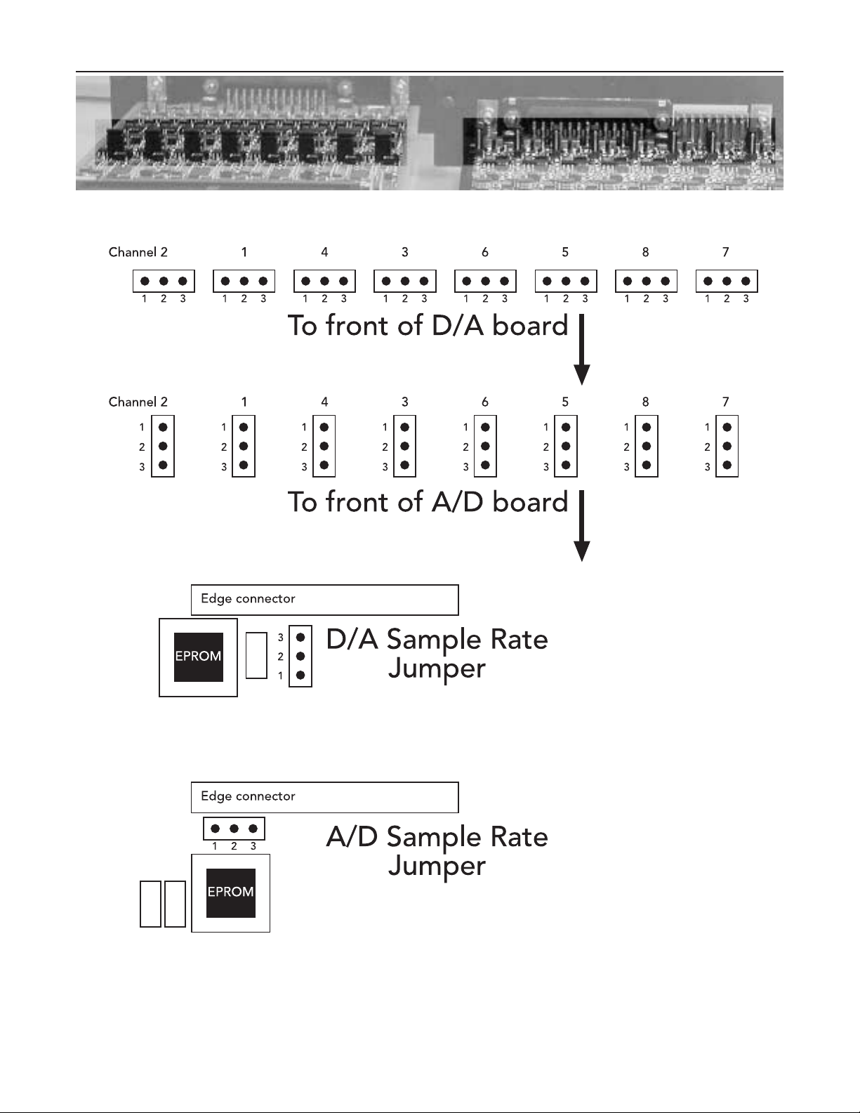
Level Setting Jumpers
The AP8AD and AP8DA cards allow three different operating levels to be defined by using jumpers on the
boards, located as shown in the photograph and diagrams on the next page. The default setting is an input/output level of 18 dBu.
High Sample Rates
On both the AP8AD and AP8DA, a jumper near the EPROM sets 44.1/48 or 88.2/96 kHz sample rates.
Jumper position 1 and 2 for 88.2/96 kHz; jumper pins 2 and 3 for 44.1/48 kHz. See illustration on the next page
for jumper location. The high sample rate setting is not currently compatible with the 02R, 03D or 01V. Note:
Your system has to be capable of 88.2/96kHz operation for the high sample rate setting to function correctly. This may require a Yamaha system software upgrade! It is expected that future versions of Yamaha
system software will include support for 88.2/96 kHz operation. When Yamaha’s software has been upgraded
to include software control of the high sample rate setting, an EPROM upgrade for your AP8AD and AP8DA
cards will be available that will act upon a software command from the host to set a high sample rate. Once this
has been done, the jumpers will be ignored.
Troubleshooting
Troubleshooting application notes will be posted on the Apogee Web site at http://www.apogeedigital.com.
AP8AD & AP8DA Card Installation Guide
Page 10
The compression curve for Apogee’s Soft Limit
AP8DA D/A CARD
Jumper pins 1+2 for 0VU = –14dBFS (18dBu max output)
Jumper pins 2+3 for 0VU = –20dBFS (24dBu max)
Remove jumper for –10 dBV consumer level (4dBV max)
(looking from the front, Pin 1 is to the left)
AP8AD A/D CARD
Jumper pins 1+2 for –10 dBV consumer level (4dBV max in)
Jumper pins 2+3 for 0VU = –14dBFS (18dBu max)
Remove jumper for 0VU = –20dBFS (24dBu max)
(pin 1 is closest to the edge connector;
pin 3 is towards the FRONT of the card)
No compression
Standard compressor
Soft Limit®
Page 11
AP8AD & AP8DA Card Installation Guide
Page 11
View of cards from rear. Highlighted rectangle indicates position of level-setting jumpers,
D/A card on the left, A/D card on the right.
How to locate the jumpers on your card. Top: The D/A card level-setting jumpers are located about half-way
down the populated part of the board; the A/D card jumpers are a short distance behind the front panel.
Bottom: The sample rate jumpers are located next to the EPROM adjacent to the edge connector at the back
of the populated part of the board.
Page 12

A/D Card Compatibility
Please note that there are some limitations to the application of the Apogee AP8AD A/D
converter card.
The following compatibility considerations affect the AP8AD Analog/Digital conversion card:
1 Due to power supply limitations in the Yamaha 03D, the AP8AD will not function reliably in that product.
This issue may be resolved in a later revision of the AP8AD.
2 When the AP8AD is installed in slot 3 or 4 of a Yamaha 02R, the slot immediately below the AP8AD should
not be used for an AP8DA card, although it may be used for Yamaha YGDAI cards.
3 The AP8AD, AP8DA and similar cards require the hosts system’s firmware to “recognize” the card in order
for it to function. At present, the 01V firmware does not contain the information necessary to recognize the
Apogee AP8AD and AP8DA cards, although a future Yamaha update may enable it to do so. Please contact
Yamaha for further information.
No such special considerations affect the
AP8DA Digital/Analog conversion card, with the exception of the
incompatibility with the Yamaha 01V, because current Yamaha software does not recognize the card.
If you have an application in which these limitations are causing you a problem, please contact Apogee Technical
Support as detailed in the front of this manual. We may be able to offer a solution.
Rev X1 – May 11, 2000.
AP8AD & AP8DA Card Installation Guide
 Loading...