

Page 1
Page 1
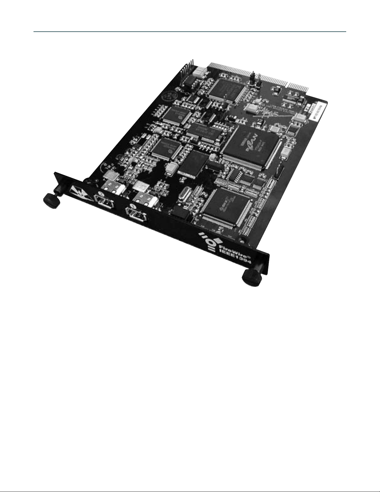
AMBus FireWire Card
Introduction
The Apogee FireWire card employs the mLAN format developed by Yamaha.
The mLAN format is based on the industry standard IEEE 1394 “FireWire” data interchange specification,
customized specifically for audio and music applications. With mLAN, it is possible to carry digital audio and
MIDI information via a single input/output cable linking each unit. It is also possible to connect FireWire hard
drives, CD/DVD drives, and mLAN-compatible audio devices together in one chain to a FireWire equipped computer. Every device in the chain is automatically identified by the computer and, as a result, setup is remarkably
straightforward. This simplifies configuration and troubleshooting while allowing flexible and sophisticted digital routing with multiple devices.
The amount of data that FireWire devices can pass is measured in Megabits per second (Mb/s) and the speed
of a given device is designated by the letter S followed by the maximum supported data rate in Mb/s. Thus a
device listed as “S100” would be capable of passing data at 100Mb/s. The Apogee card is rated as S200, and
therefore supports speeds of up to 200Mb/second. This information is important when maximizing the efficiency of an entire FireWire system. See “Optimizing FireWire Setup” for more information.
AMBus FireWire Card Operating Manual
Page 2

Installing the AMBus Card
To install the AMBus card, first make sure the power is turned off. You may wish to keep the unit plugged
into a switched-off, grounded AC receptacle so as to minimize the chance of static discharge, and avoid standing on carpeting while carrying out this procedure. Keep the new AMBus card in its packaging until you are
ready to install. Now turn the unit around so you’re facing the back panel. Remove the plate covering an available AMBus slot. Ground yourself by touching a connector on the unit’s rear panel and unpack the card. Locate
the card between the guides and insert the card until you feel it mate with the connector at the back of the card
bay. Fasten the card in place with the captive screws.
Installing the FireWire Card software
In order for the computer to recognize the card and send and receive digital audio, the mLAN drivers,
extensions and applications need to be installed in the correct places in the computer. These items can be
downloaded from Apogee’s website at http://www.apogeedigital.com/firewire/.
Refer to your platform and OS below for details on your specific setup. At present, Macintosh OS 8.6 to 9.x
is supported. Please check the web site address above for information regarding other operating systems as
they are supported.
Installing the mLAN Driver
May 31, 2002—mLAN Driver/MacOS9 1.0.4b3
Installation Process
1. Make sure you have one of the following OS and FireWire version combinations.:
a. Mac OS 8.6 or later, and FireWire 2.1 or later.
b. Mac OS 9.0 or later and FireWire 2.2 or later.
Yamaha has tested up to Mac OS 9.2.2 and FireWire 2.8.5. Mac OS X is not currently supported.
The version number of the OS can be found by executing "About This Computer" in the Apple menu. The version number of FireWire can be found by selecting the "FireWire Support" file, "FireWire Enabler" file, and by
executing "Get Info" in the File menu. These files are in the Extensions Folder in the System Folder.
2. If you use mLAN with OMS, install OMS prior to the installation of mLAN driver.
3. Put "mLAN Driver", "mLAN Expert", and "mLAN Family" into an extensions folder in the System Folder. If
any older versions exist, disable them.
*You might be tempted to drag them into a System Folder, however, "mLAN Expert" won’t be put into
Extensions Folder automatically. Instead, it will be put into the System Folder. Make sure you physically place
them in the Extensions Folder yourself.
4. Put "mLAN Control Panel" into the Control Panels folder. If an older version exists, place the older version
into a separate folder first.
5. Reboot your Macintosh.
6. Set up the mLAN parameters on the mLAN Control Panel depending on your preference.
*See the rest of this document and the mLAN Control Panel manual for details.
7. If you use mLAN with OMS, put "mLAN OMS Driver" into OMS Folder in the System Folder so OMS Studio
Setup application can recognize it.
8. If you use mLAN from ASIO compatible applications, put "ASIO mLAN" into ASIO Drivers folder of those
applications.
FireWire Card Usage
*IMPORTANT: You must configure the mLAN control panel (below) before starting the recording application
in order for the application to recognize the FireWire card.
AMBus Card Operating Information
Page 2
Page 3
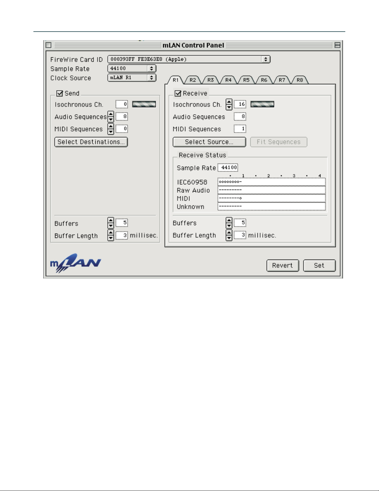
Fig. 1
mLAN Control Panel Features (Fig. 1)
• FireWire Card ID: Selects the desired FireWire card on the computer to be used for mLAN data transfer.
• Sample Rate: Sets the sample rate for the digital audio data sent via mLAN.
• Clock Source: Selects the clock source for the entire FireWire chain.
• Send: Enables “Send” section to be configured in order for the recording application to send digital audio
to the external mLAN device.
• Audio Sequences: Specifies the number of audio sequences, or mono audio channels, transmitted from the
computer to the selected source.
• MIDI Sequences: Specifies the number of MIDI sequences (each MIDI sequence is equal to one MIDI cable)
transmitted from the computer to the selected source.
• Select Destinations: Opens destination window (see figure 2 below) to allow selection of mLAN device to
receive mLAN data from the computer.
AMBus FireWire Card Operating Manual
Page 3
Page 4

Fig. 2
“Select Destinations” window features (Fig 2)
1 Destinations: These drop-down menus on the left of the window enable you to select available mLAN
devices to which data can be transmitted.
Tip: Hold down the “option” key (Mac) to select the same mLAN device for all available destinations.
2 Input Channels: These drop down menus on the right of the window enable you to select input channels of
the receiving mLAN device.
Tip: Hold down the “option” key (Mac) to select consecutive input channels on the same mLAN device.
3 Disconnect All: Click this button to disconnect the assigned destinations from mLAN control panel trans-
mission.
4 Update: Click this button to have the system rescan the connected mLAN devices to update their status.
Use this button after making manual changes to connected devices.
5 Revert: Click this button to set all parameters to their status when the “Select Destinations” window was
first opened.
6 OK: Click this button to assign the settings made and to close the “Select Destinations” window.
7 Cancel: Click this button to close the “Select Destinations” window without saving changes.
AMBus Card Operating Information
Page 4
Page 5

mLAN Control Panel Features (Fig 1) continued
• Buffers: Specifies the number of buffers in the mLAN driver. Note that there is a set of buffers for the send
section (applies to the data transmission buffer) and a set for the receive section (applies to the data recep-
tion buffer).
• Buffer Length: Specifies the length (1–100 milliseconds) of each buffer in the mLAN driver. Notice that, as
with the number of buffers setting, there is a separate parameter for the send and receive sections.
• Receive: Enables “Receive” section to be configured in order for the recording application to receive digi-
tal audio from the external mLAN device.
• Audio Sequences: Displays the number of audio sequences (mono channels) present in the received mLAN
data. If this number does not match the actual number in the received data, then a red “Not Match” warn-
ing will flash to the right. Click on “Fit Sequences” to automatically match this parameter to the data being
received.
• MIDI Sequences: Displays the number of MIDI sequences (each MIDI sequence is equal to one MIDI cable)
present in the received mLAN data. If this number does not match the actual number in the received data,
then a red “Not Match” warning will flash to the right. Click on “Fit Sequences” to automatically match this
parameter to the data being received.
• Select Source: Click this button to select the mLAN device to which the recording application sends data.
This will open the “Select Source” window (see below).
Fig. 3
“Select Source” window features (Fig 3)
1 Device List: Select the desired mLAN device from which you would like to receive data.
2 Output Plugs: This list shows all channels present from the selected mLAN device source.
3 Disconnect: Click this button to disconnect the assigned sources from mLAN control panel transmission.
4 Update: Click this button to have the system rescan the connected mLAN devices to update their status.
Use this button after making manual changes to connected devices.
5 Revert: Click this button to set all settings to their values when “Select Source” window was first opened.
6 OK: Click this button to assign the settings made and to close the “Select Destinations” window.
7 Cancel: Click this button to close the “Select Destinations” window without saving changes.
AMBus FireWire Card Operating Manual
Page 5
Page 6

mLAN Control Panel Features (Fig 1) continued
• Fit Sequences: Clicking this button will automatically match the number of audio sequences displayed to
actual number present in the incoming mLAN data.
• Receive Status: This section displays the current status of some important parameters of the incoming
mLAN data.
• Revert: Click this button to return all settings to their values when the mLAN control panel was first opened.
• Set: Click this button to save any changes you’ve made.
Configuring the mLAN control panel
Fig. 1
• Open the mLAN control panel. (see fig. 1 above)
• Set the desired sample rate.
• Set the desired clock source:
Internal – The mLAN control panel software will generate the clock.
External (preferred) – The device (Trak 2 or AD-8000) in which the FireWire card is installed will be the mas-
ter clock (set to “crystal”).
Note: When setting the control panel to “external”, you must still manually set the sample rate in the mLAN
control panel to the incoming rate. The control panel will not automatically switch to the incoming rate.
• Ensure that “Send” and “Receive” boxes are checked to enable record and playback operation.
• In the “Send” column, click “Select Destinations”. (see fig. 2)
AMBus Card Operating Information
Page 6
Page 7

• Select the device to which you want to send audio data.
• In the “Receive” column, click on “Select Source” (see fig. 3).
• Select the device from which you want to receive audio data.
• Set the desired number of buffers. Note that there are different settings for the send and receive sections.
Each buffer size is determined by the “Buffer Length” field (see below). The number of buffers, multiplied
by the buffer length, will produce the total amount of latency added by the mLAN driver for the send or
receive section. The lower the setting, the lower the latency time. However, slower computers may not run
smoothly at low settings. Start with a setting of 2-3 buffers per side and adjust accordingly from there to
achieve a balance of smooth operation and acceptable latency.
• Set the desired “Buffer Length”.
This field determines the size (in milliseconds) of each buffer. As stated above, the product of the buffer
length and number of buffers will be the total amount of latency added by the mLAN driver. As a rough
starting point, set the buffer length to about 3 milliseconds for both send and receive sections. Again, adjust
accordingly from there to achieve a balance of smooth operation and acceptable latency.
When the steps above are completed, you must click on “Set” in order to activate these settings. At this
point, the control panel is set up for proper recording and playback. You may quit the control panel and open
up your recording application. Configure the recording application for use with FireWire (see “Configuring
Recording Application” below).
*NOTE: Increasing the number of buffers and the buffer size yields smoother performance but longer latency.
Decreasing the number of buffers and buffer size shortens latency time at the cost of system performance.
These two parameters must be adjusted to suit your system performance and your needs. See “User Tips” for
additional information on getting the best performace out of your FireWire card setup.
Configuring Recording Application (for use with FireWire)
• Open the recording application.
• In the setup menu (this will vary depending on the application), choose the option for “ASIO mLAN”. This
tells the application to send and receive audio data via the mLAN driver.
Setup examples:
• For MOTU Digital Performer, go to the Basic menu/Audio System and choose “ASIO mLAN”. Click OK.
• For Steinberg Nuendo, go to the Devices menu/Device Setup/VST Multitrack and choose “ASIO mLAN”.
Click OK.
• For eMagic Logic, go to the Audio menu/Audio Hardware and Drivers. Click on the triangle next to the
“ASIO” box to open the ASIO section. Choose “mLAN” in the “Driver” drop-down menu. Click OK.
*NOTE: Setup in your specific recording application may vary. If your application is not listed in the examples
above, and you’re not sure were to find the above settings, check your application’s user manual for setup information.
Appication Notes
If your Apogee FireWire card exhibits instability, you may find these notes useful.
In the mLAN Control Panel:
• If the audio seems to drop out frequently, the buffers are probably being overrun. Set the number of buffers
to a higher value and increase the buffer length. Note, however, that this will result in higher latency.
• For smoother performance without adding latency, try using more buffers with fewer milliseconds per
buffer. For example, instead of 2 buffers with 3 milliseconds each, try 6 buffers with 1 millisecond each.
AMBus FireWire Card Operating Manual
Page 7
Page 8

• If the card generally has a difficult time settling down, try setting the clock source (see “Configuring mLAN
Control Panel) after all other parameters are set, then click “set”. Note that it can take a few seconds for
the FireWire chain to lock onto the clock source. During these few seconds, you may see a flashing red error
message.
• It is sometimes helpful to switch the sample rate on the control panel to another sample rate, then back to
the desired rate. This can ‘reset’ the way the mLAN control panel looks for clock in the FireWire stream. It
is also a good idea to switch the sample rate back and forth on the device in which the Apogee FireWire
card is installed, when resetting the clock in the control panel.
Note: It is always necessary to click “Set” after changing any parameter in the mLAN control panel.
After clicking “Set”, it is almost always necessary to reassign the destinations by clicking on the “Select
Source” button under the “Receive” section of the mLAN control panel.
• If the FireWire card is not plugged into the computer port on boot up, you may get an error from the mLAN
control panel indicating that there is no FireWire card installed, even on a computer with a built in FireWire
port. A restart with the connections intact will resolve this problem.
• If any recording application using the mLAN ASIO driver is running, the mLAN control panel will not allow
changes, reporting that “some streams are in use”. Close the recording application and then reopen the
mLAN control panel to rectify the problem.
After the changes described above are made, the control panel should settle into smooth operation.
The following additional tips may be useful if you continue to experience difficulties.
Macintosh OS 9.x:
• In the Extensions Manager, create an Extensions Set from the OS Base setting; deactivate Apple Enet and
TCP/IP; and activate only those extensions needed for the application you’re running (for example, you’ll
need to active iLok extensions for Nuendo, as well as OMS if you’re using it).
• Check in the Energy Saver Control Panel’s Sleep Schedule page that all parameters are set to NEVER.
• Finally, Yamaha recommends, especially with Titanium PowerBooks, that the FireWire connection be made
first, then the Apogee unit powered up, and finally the computer.
Optimizing FireWire Setup
In order for your FireWire setup to achieve peak performance for data transfer, we suggest you follow this
basic guideline for interfacing multiple devices.
As explained in the introduction, all FireWire devices are rated at a specific speed. Connecting two devices
with different speeds will result in both units running at the lower of the two speeds. This is easy to comprehend in a simple setup with only two devices.
Let’s consider a system with a FireWire-card-equipped Apogee Trak 2 and a computer. The computer’s
FireWire specification may be rated as S400, capable of a 400Mb/s transfer rate. The Apogee FireWire card is
rated at S200. These two devices connected via FireWire will be able to achieve a maximum data transfer rate
of 200Mb/s.
Larger setups consisting of numerous devices with different transfer rates will perform better if connected
in relation to each units speed rating. The diagram on the next page (Fig. 4) illustrates a setup with five devices.
In this setup, devices A and B are rated at 400Mb/s, device C is rated at 200Mb/s, and devices D and E are
rated at 100Mb/s.
AMBus Card Operating Information
Page 8
Page 9

This connection scheme is best for a few reasons:
•A and B are able to communicate at their full 400Mb/s rate.
•C is able to communicate to B at its full 200Mb/s.
•D and E communicate at 100Mb/s.
•D and A communicate at 100Mb/s.
If we were to place device C between A and B, then device A would not be able to use its full transfer rate,
as it would default to 200Mb/s since it is hooked up to C.
It is best to use slower devices at the ends of the FireWire chain, and try to connect similarly rated devices
together without slower device in between.
Fig 4
AMBus FireWire Card Operating Manual
Page 9
A = S400
B = S400
C = S200
D = S100
E = S100
 Loading...